
J. Cent. South Univ. (2012) 19: 365-373
DOI: 10.1007/s11771-012-1013-6![]()
Dual cycloid gear mechanism for automobile safety pretensioners
SHIN Joong-ho, KIM Chang-hyun, YUN Pyeong-hwa, KWON Soon-man
Department of Mechanical Design and Manufacturing, Changwon National University, Changwon 641-773, Korea
? Central South University Press and Springer-Verlag Berlin Heidelberg 2012
Abstract:
The most conventional vehicle pretensioner system consists of an internal gear pair with involute teeth. However, it has been well known that the corresponding gear pairs are relatively weak under the situation of impact loadings. To improve this phenomenon, a new pretensioning gear system with cycloid teeth rather than the involute ones was proposed, and dual cycloidal gear mechanisms were designed for satisfying geometric constraints and dynamic loading conditions. The simulations of the prototypes were conducted by LS-DYNA program and the experiments for a prototype were performed for a dynamic model with impact loading devices. The results show that the better operation and the smoother motion are confirmed in the proposed cycloidal gear system rather than the conventional one without interferences between gear teeth under the impact of a crash.
Key words:
seat belt; pretensioner; internal gear pairs; involute gear; dual cycloid gear��
1 Introduction
Protection systems to head off automobile accidents and effective automobile passenger protection systems have been aroused as recent issues according to improvements in automobile performance. Regarding seat belts and airbags that are the major protection systems in automobiles, the seat belts play the role to protect passengers and reduce damages at a sudden stop or crash. The pretensioner in protection system ensures the best position of passenger to airbags by tightening the passenger to the seat through rewinding safety belts at an automobile crash. Thus, researches and developments for specifying safety factors in these issues and developing models have been conducted by global automobile and component manufacturers. Also, studies on the method for achieving dynamic analyses and effective experiment verifications through considering the connection action of human body to seat belt systems with the pretensioner have been processed [1-8]. In addition, studies on the mechanism for obtaining more excellent performance have been actively conducted [9-10].
The gear, which is the core part of the conventional pretensioner, is generally formed by involute teeth that may cause some deformations and damages of the gear teeth by strong impact loads due to the operational characteristics. In the basic idea of pretensioner, it represents a structure that has a sufficient gap between its housing and gear at the initial standby state as a non-contact state. Then, it generates sudden gearing and a smooth rotational motion between these gapped gears for electric signals of crash. However, unsafe motions frequently occur due to uneven gearing caused by some deformations and damages of teeth in the conventional model which cause a wrong calculation in the amount of web retraction. Thus, JUNG et al [11] designed a rack-pinion gear system for the pretensioner and proposed an optimal design combination for obtaining the target amount of web retraction through computer aid engineering (CAE) analyses and experiments. Because the amount of web retraction is a result of precise gearing, JUNG et al [12] developed an operation mechanism of the pretensioner using an internal gear with involute teeth and evaluated its performance. Although the conventional system improved some fine functions by adjusting the gear ratio, center distance and module in such a contact gear, an issue of smooth rotation on the basis of modifying gear tooth shapes was still not solved.
In this work, some fundamental issues on such involute gear teeth were analyzed and the involute teeth were changed to cycloid teeth [13-15] in order to complement pretentioner models. Then, the analysis and experiment for the modeling and prototype of this new design were performed.
2 Analysis of conventional system
2.1 Basic structure of conventional model
Figure 1 shows the extending and entire drawings of the pretensioner applied in this work. Also, Fig. 2 shows a drawing that represents gaps between parts, which considers a characteristic of sensitivity products. The Position 1 as presented in Fig. 2, indicates a gap of (0.4��0.1) mm between spool and frame. Position 2 shows a gap of (0.4��0.1) mm between spool and ring gear and Position 3 in external side indicates a gap of (0.1��0.05) mm between ring gear and housing.
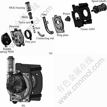
Fig. 1 Shape of pretensioner: (a) Elements of pretensioner; (b) Assembled model
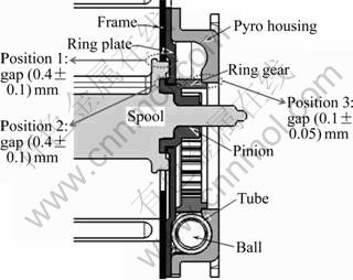
Fig. 2 Gaps between parts
Figure 3(a) illustrates a set position of operation where the spool is fixed at the pinion, and the ring gear and pinion are separated, which does not affect the rotation of spool. Therefore, the tooth shape of pinion is flexibly changed according to the rotation of spool. Figure 3(b) shows the early stage of gearing between the ring gear, which is rotated by a connecting rod caused by an explosion due to the crash and the pinion.
2.2 Experimental analysis of conventional model
Regarding the conventional pretensioners that are formed by involute teeth, five different pretensioner samples with involute teeth having a pressure angle of 20�� were fabricated (see Table 1) and applied to the experiment. According to the results of experiment, it is verified that all samples do not approach to the initially determined target rotated angle of the pinion more than 275��.
There are some damages and deformations due to the shocks caused by the teeth as expected in the fabricated samples even though certain differences in their damages. In particular, Case I4, which is the severest case, showed a fault of gearing due to the excessive deformation in its tooth shape and then the ring gear was rotated only.
Figures 4 and 5 represent the prototypes after completing the experiments for Case I1 and Case I5. The ring gear, i.e., Case I1, as shown in Fig. 4, indicates a large deformation in its tooth shape. Although Fig. 5, i.e. Case I5, shows a satisfied result compared to other samples, the first tooth is largely deformed due to a large impact load and the tooth shape of pinion is severely damaged.
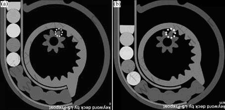
Fig. 3 Operation of pretensioner gear: (a) Set position; (b) Initial retracted position
Table 1 Specifications of involute gear teeth
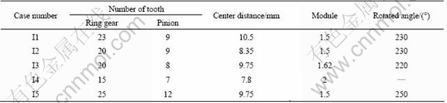
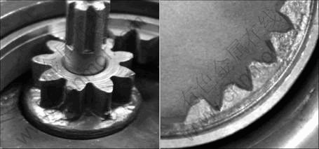
Fig. 4 Teeth of gearing for Case I1
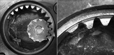
Fig. 5 State of teeth of gear rotation for Case I5
2.3 Analytical analysis of conventional model
For implementing motion and crash analyses in a dynamic state, LS-DYNA, a nonlinear finite element analysis program, was used and the results of the analysis and experiment were compared.
In the results of the analysis of Case I3, given in Table 2, although the degree of rotation was not satisfied, it showed no large smudges in tooth shapes. In the case of the conventional tooth shape, the analysis was carried out for both the pressure angle of 20�� and the pressure angle of first tooth of pinion which changed to 25��. It is verified that the conventional tooth shape shows a large deformation at the second tooth. Also, in the results of the changed tooth shape analysis, the deformation was reduced. Thus, it is considered that the pressure angle plays an important role in a factor of deformation in impact loads.
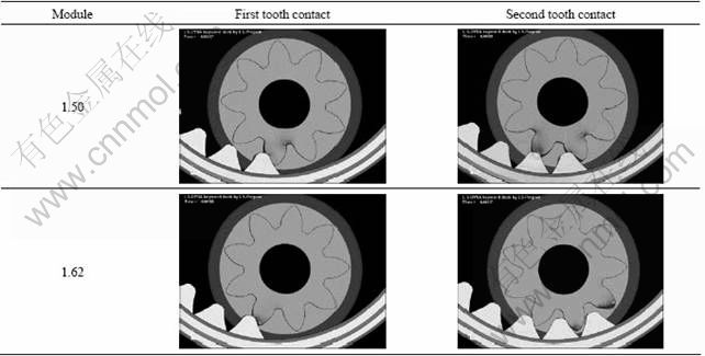
Table 3 shows the results of the analysis of smooth rotation by varying the module in order to adjust the contact point of teeth. In the case of the module of 1.62, it indicates that smooth rotation as its interference is significantly improved compared with that of the module of 1.50. Therefore, it is recognized that the number of teeth, module and center distance are to be compositively considered for avoiding such interference.
Table 2 Deformation in first tooth gearing for Case I3
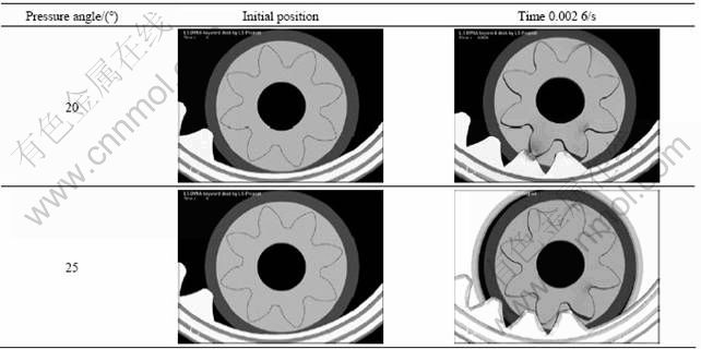
Table 3 Interference of gearing for Case I3
3 Design of cycloid gear shapes
3.1 Kinematic model
Cycloid teeth show a smaller sliding speed occurring at its gearing than that of involute teeth which makes it possible to precisely transfer motions. Also, cycloid teeth have some advantages, such as high durability, low noise and properly minimizing a pretensioner device, has been largely limited in its installation space. However, cycloid teeth have not been widely used in practical applications due to the difficulties in design and machining even though they have such advantages.
As cycloid gears are moved while they are always contacted, the gears require precise shape design, high precision and surface roughness. Also, because the gears are a type of roller gear that has a circular roller as a tooth in its gearing compared with that of involute teeth, the shape of cycloid gears are complicate but it is possible to design a shape of simultaneous contact.
In this work, a cycloid tooth shape was implemented through changing the instantaneous center and coordinate transformation of the speed proposed by SHIN and KWON [13].
Figure 6 illustrates a dual cycloid gear pair with cycloid teeth as a type of internal gear. The ring gear is fixed by maintaining a continuous contact with the pinion gear. The pinion gear is rotated about the center of ring gear, O1, as an orbital motion and represents a spin motion about the eccentric center of O2.
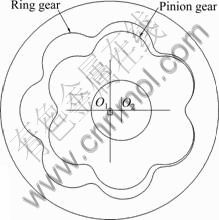
Fig. 6 Shape of dual cycloid gear pair
The shape of cycloid teeth was designed by configuring a condition that has no interference by maintaining the modules of two gears after determining the amount of rotation by the difference in the number of teeth between two gears as a design variable. In addition, as shown in Fig. 7, an operable pretensioner is formed by removing teeth in a specific section.
Figure 8 shows the shape parameters of dual cycloid. Parameters R1 and R2 represent the distances from the centers of the pinion gear, O1 and O2, to the center of pin gear, respectively, and N1 and N2 represent the numbers of pin gears, respectively. Also, DC shows the center distance between two cycloid gears. Due to the mechanism characteristic of the dual cycloid, the eccentricity, E, and the radius of pin, Rr, are same.
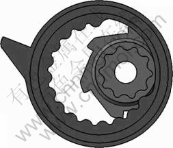
Fig. 7 Modeling of pretensioner gears using dual cycloid gear pair
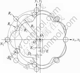
Fig. 8 Design parameters of dual cycloid
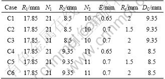
The parameters R1 and N1 in the ring gear were determined as 17.85 and 21, respectively, and six different cases were selected for the pretensioner by varying the parameters of R2, N2, E, Rr, and DC. Then, the analysis for these parameters was performed. In the results of this analysis, it is considered that Case C6 is the most proper configuration. Table 4 gives the design parameters of the cycloid gears.
3.2 Changes in center distance
As an explosion of powder, the balls inserted in a tube collide with the externally projected section of the ring gear and the power caused by the collision rotation of the ring gear. Then, the gearing between the ring gear and the pinion occurs. This process was analyzed using LS-DYNA.
Regarding the case of C6, the gear was designed as a proper shape for the gearing with its tooth height and width. The center position of pinion was varied in order to increase the gearing ratio with the pinion while the
Table 4 Design parameters of cycloid gears
ring gear was fixed and enable the normal rotational motion of ring gear. Table 5 gives some cases for determining an optimal center distance.
In the results of the analysis, there is a thrust gap as much as the gap between pinion and ring gear. Then, the initial gearing of first tooth occurs. The second tooth presents a certain delay because it needs time for precise gearing. Since then the gearing is normally performed even though there are some small gaps.
Table 5 Changes in center distance
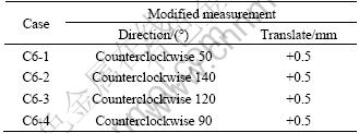
Figure 9 shows the gearing between the first and the second tooth with respect to the cases listed in Table 5. It is verified that the smooth rotation can be performed according to the increase in the amount of the gearing in teeth for C6-4.
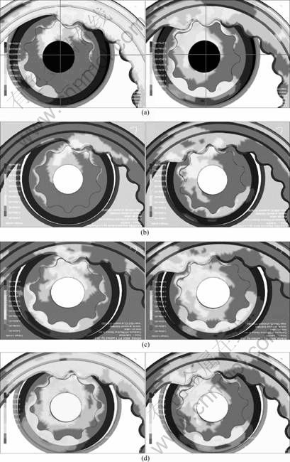
Fig. 9 Dynamic analyses for internal gearing: (a) Case C6-1; (b) Case C6-2; (c) Case C6-3; (d) Case C6-4
3.3 Changes in module
For the gaps between elements illustrated in Fig. 2, the gap between pinion and ring gear is 0.5 mm and the ring gear shows a thrust gap as much as the thrust gap of ring plate (see Fig. 2(a)) as the gearing between two gears. To reduce such gaps and thrust motions, the module of pinion for C6-4 was changed from 0.85 to 0.895 for presenting a smooth rotational motion. It was possible due to the fact that although there was a difference in the module between two gears, it did not affect the rotational motion largely.
Figure 10(a) illustrates the shape of an offset state by varying the module of pinion while the center distance of the gear is maintained. Figure 10(b) shows an adjusted shape that indicates a contact state between two gears by moving the center of the pinion.
3.4 Dynamic analysis and prototype evaluation
Figure 11 shows a dynamic state of the gear for the case of modifying the module of C6-4. Figure 12 shows the modified state of the tooth shape through experiments. In the results of the experiment, there is a getting over in the pinion teeth due to the deformation of the pinion teeth that was not presented in its analysis and that had failed to obtain the wanted amount of web retraction.
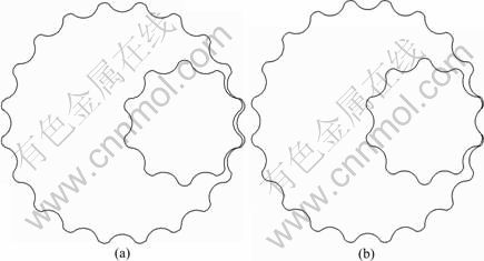
Fig. 10 Modified design for case of C6-4: (a) Offset profile; (b) Translating gearing
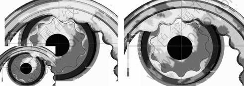
Fig. 11 Dynamic state of modified case of C6-4
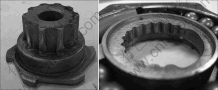
Fig. 12 Prototype evaluation of modified case of C6-4
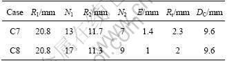
To reduce such a getting over and increase the strength for the gear tooth shape, R1 and R2 are to be increased and N1 and N2 are to be decreased under the same condition in order to increase the size of teeth and the amount of gearing. Then, the dynamic motion is verified under this state. Table 6 gives the design specification of the finally determined cycloid gear.
Figure 13 shows the results of dynamic analyses of cases C7 and C8. Figure 14 illustrates the prototype by following the design performed in this work. The final product passes the evaluation test.
Table 6 Design parameters of modified cycloid gears
The gear, made of S45C and HRC 40, is used to the heat treatment of the gear. Also, the surface is finished using a zinc coating with PFZn8-C. In the operation under the same condition, there are no deformations in the gear and the ring gear is sufficiently rotated until it collides with the tube.
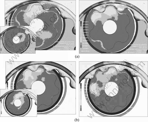
Fig. 13 Dynamic analyses for C7 (a) and C8 (b)
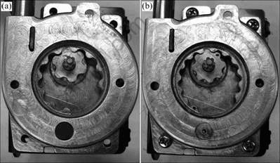
Fig. 14 Final prototypes of cases of C7 (a) and C8 (b)
4 Conclusions
1) To improve the severe deformation and damage in the involute gear teeth of conventional pretensioner device, a new cycloidal gear system was proposed in this work.
2) The experiments and the simulations of some prototypes, a chosen final prototype show the better operation and the smoother motion without interference between gear teeth as well as less deformation and damage rather than the conventional gear system.
References
[1] KUK M G, KWON S J, TAK T O. Dynamic analysis of seat belt systems with anti-inertial release mechanisms [J]. International Journal of Automotive Technology, 2008, 9(5): 593-599.
[2] KURUTAS C, ELSABER K, SCHRAMM D, HILLER M. Modeling and simulation of the effect of reversible belt pretensioners [C]// Proceedings of Mechatronics 2006 IEEE International Conference. Budapest, Hungary, 2006: 119-124.
[3] LEE Y B, RYU W H, HYUN I A. Leveraging the development of the high-power pretensioner using CAE and evaluate the influences to injuries [C]// Proceedings of MSC Korea User��s Conference. Seoul Korea, 2007.
[4] MIN S K, LEE J K, KIM B S. Development of pre-crash safety system using motorized seat belt [C]// Proceedings of Korean Society of Automotive Engineers Fall Conference. Gunsan-si, Korea, 2004: 1219-1224.
[5] PARK C S, PARK T W, JUNG S P, CHEONG K Y, HONG Y S. Study on the dynamic analysis of a high-power pretensioner considering the clutch effect [C]// Proceedings of Korean Society for precision Engineering Spring Conference. Seoul Korea, 2008: 221-222.
[6] JUNG C K, NA B C, KIM H Y, WOO S W. Structure analysis of seatbelt system [C]// Proceedings of Korean Society of Automotive Engineers Fall Conference. Daegu, Korea, 1999: 1523-1528.
[7] SIMON X H, MICHAEL D W. A method to evaluate the energy capability of seat belt pretensioners [C]// Proceedings of Society of Automotive Engineers 1999 International Congress and Exposition of Adviances in Soft Technology. Detrit, USA, 1999: 25-29.
[8] CZERNAKOWSKI W, BELL R. The effects of belt pretensioners on various child restraint designs in frontal impacts [C]// Proceedings of Society of Automotive Engineers 1997 International Congress and Exposition of Adviances in Soft Technology, 1997: 217-229.
[9] SHIN Y J, KIM H, KIM S B. Injury performance evaluation of the child restraint systems [J]. International Journal of Automotive Technology, 2007, 8(2): 185-191.
[10] KENT R W, PURTSEZOV S V, PILKEY W D. Limiting performance analysis of a seat belt system with slack [J]. International Journal of Impact Engineering, 2007, 34(8): 1382- 1395.
[11] JUNG S P, PARK T W, SONG T R. Analytical study in the performance of a high power [J]. International Journal of Automotive Technology, 2010, 11(2): 197-203.
[12] JUNG S P, PARK T W, KIM W H, HONG Y S. Development of operating mechanism of a pretensioner using internal gear pairs [J]. Journal of the Korean Society of Precision Engineering, 2010, 27(3): 89-94. (in Korean)
[13] SHIN J H, KWON S M. On the lobe profile design in a cycloid reducer using instant velocity center [J]. Mechanism and Machine Theory, 2006, 41(5): 596-616.
[14] YUN P H. A study on design and materialization in conjugate dual cycloid [D]. Changwon National University, Republic of Korea, 2010. (in Korean)
[15] LITVIN F L. Gear geometry and applied theory [M]. PTR Prentice Hall, Englewood Cliffs, 1994: 403-406.
(Edited by DENG L��-xiang)
Foundation item: Work financially supported by the Changwon National University in 2011-2012, Korea
Received date: 2011-05-24; Accepted date: 2011-10-10
Corresponding author: KWON Soon-man, Associate Professor, PhD; Tel: +82-55-213-3629; E-mail: smkwon@changwon.ac.kr
Abstract: The most conventional vehicle pretensioner system consists of an internal gear pair with involute teeth. However, it has been well known that the corresponding gear pairs are relatively weak under the situation of impact loadings. To improve this phenomenon, a new pretensioning gear system with cycloid teeth rather than the involute ones was proposed, and dual cycloidal gear mechanisms were designed for satisfying geometric constraints and dynamic loading conditions. The simulations of the prototypes were conducted by LS-DYNA program and the experiments for a prototype were performed for a dynamic model with impact loading devices. The results show that the better operation and the smoother motion are confirmed in the proposed cycloidal gear system rather than the conventional one without interferences between gear teeth under the impact of a crash.
