
J. Cent. South Univ. Technol. (2011) 18: 2091-2099
DOI: 10.1007/s11771-011-0948-3![]()
Pseudo-dynamic analysis of seismic stability of
reinforced slopes considering non-associated flow rule
A. Eskandarinejad1, A. H. Shafiee2
1. Civil Engineering Department, University of Hormozgan, Bandar Abbas 7193619411, Iran;
2. Civil Engineering Department, Shiraz University, Shiraz 7134851156, Iran
? Central South University Press and Springer-Verlag Berlin Heidelberg 2011
Abstract:
The required reinforcement force to prevent instability and the yield acceleration of reinforced slopes are computed under seismic loading by applying the kinematic approach of limit analysis in conjunction with the pseudo-dynamic method for a wide range of soil cohesion, friction angle, dilation angle and horizontal and vertical seismic coefficients. Each parameter threatening the stability of the slope enhances the magnitude of the required reinforcement force and vice versa. Moreover, the yield acceleration increases with the increase in soil shear strength parameters but decreases with the increase in the slope angle. The comparison of the present work with some of the available solutions in the literatures shows a reasonable agreement.
Key words:
1 Introduction
Nowadays, various tools are available for stabilizing the slopes such as retaining walls, chemical grouting and using reinforcements which perhaps is the most significant one. Thus, the study of stability of reinforced slopes especially under seismic condition is of great importance. In the last three decades, the stability analysis of reinforced slopes has drawn the attention of researchers. The analytical study of stability of reinforced slopes under static condition has been carried out extensively by using the limit equilibrium method [1-2], the upper bound limit analysis [3-4], the lower bound limit analysis [5], and the slip line method [6-7]. Under seismic loading, LING et al [8] used the pseudo-static approach in conjunction with the limit equilibrium method to assess the stability and permanent displacement of geosynthetic reinforced soil structures subjected to horizontal earthquake acceleration. Later, LING and LESHCHINSKYI [9] extended LING et al��s [8] study by taking into account the effect of vertical earthquake acceleration. NOURI et al [10] applied a new limit equilibrium method named as the horizontal slice method to investigate the seismic stability of reinforced slopes. JAHANANDISH and KESHAVARZ [11] developed the slip line method to investigate the seismic bearing capacity of foundations on reinforced soil slopes. MICHALOWSKI [12] and AUSILIO et al [13] used the kinematic approach of limit analysis to compute the reinforcement strength required to prevent failure. Their solutions are based on the associated flow rule. However, the soil dilation angle (��) often has values much smaller than its friction angle (��), in practice.
Some experimental investigations are also available in the literature corresponding to the stability evaluation of reinforced slopes. HUANG et al [14] performed a series of tilting table tests to study the factors that may influence the failure mechanism of reinforced slopes. Centrifugal tests [15], full-scale model tests [16], and shaking table tests [17] are other common types of experimental researches to investigate the behavior of reinforced soils.
Numerical methods have been widely used in various geotechnical problems. The complicated and advanced softwares as well as powerful computers facilitate the solution of rigorous problems. ROWE and SODERMAN [18], and LING et al [19] applied the numerical methods to assess the stability and/or displacements of reinforced slopes. LING et al [19] conducted finite element analysis to simulate the construction response of a reinforced soil retaining wall with a concrete block facing. They observed satisfactory agreement between the predicted and measured results.
Cohesive slopes can also be used in reinforced soil structures. SAWICIKI and LESNIEWSKA [20] stated that one of the most important reasons for applying such soils is that the cost of locally available soils is much lower than respective costs for imported materials. In this work, the required reinforcement force to prevent instability and the yield acceleration of reinforced slopes are computed under seismic loading by applying the kinematic approach of limit analysis in conjunction with pseudo-dynamic method for a wide range of soil cohesion (c), friction angle (��), dilation angle (��), horizontal seismic coefficient (kh), and vertical seismic coefficient (kv).
2 Method of analysis
2.1 Kinematic approach of limit analysis
In order to use the conventional form of the kinematic approach of limit analysis, it is assumed that the soil obeys the associated flow rule, i.e., the velocity vectors make an angle equal to the soil friction angle (��) with the corresponding failure surfaces. In any kinematically admissible mechanism, the rate of internal energy dissipation is not less than the rate of work of external loads:
![]() (i, j=1, 2, 3) (1)
(i, j=1, 2, 3) (1)
where ![]() is the strain rate in the kinematically admissible velocity field,
is the strain rate in the kinematically admissible velocity field, ![]() is the associated stress, Xi is the body force including the soil weight and seismic inertia forces, vi and
is the associated stress, Xi is the body force including the soil weight and seismic inertia forces, vi and ![]() are the velocities on loaded boundary S and volume V, and ti is the traction. The kinematic theorem of limit analysis yields that collapse must occur if, for any kinematically admissible mechanism, the rate of working of the external forces on the body equals or exceeds the rate of internal energy dissipation. In the kinematic approach of limit analysis for reinforced soils, the soil and the reinforcements are supposed to be in the plastic state. Moreover, it is assumed that the soil is homogeneous following the Mohr-Coulomb failure criterion and the reinforcements (geosynthetic) are tensile members which do not have any resistant to compression, shear, flexure, and torsion. Thus, only the energy dissipation rate due to the tension in the reinforcements is put in the equation of the kinematic theorem. Furthermore, the soil/reinforcement interface is assumed to exclude any weak surface. The energy dissipation rate of reinforcements can be calculated by
are the velocities on loaded boundary S and volume V, and ti is the traction. The kinematic theorem of limit analysis yields that collapse must occur if, for any kinematically admissible mechanism, the rate of working of the external forces on the body equals or exceeds the rate of internal energy dissipation. In the kinematic approach of limit analysis for reinforced soils, the soil and the reinforcements are supposed to be in the plastic state. Moreover, it is assumed that the soil is homogeneous following the Mohr-Coulomb failure criterion and the reinforcements (geosynthetic) are tensile members which do not have any resistant to compression, shear, flexure, and torsion. Thus, only the energy dissipation rate due to the tension in the reinforcements is put in the equation of the kinematic theorem. Furthermore, the soil/reinforcement interface is assumed to exclude any weak surface. The energy dissipation rate of reinforcements can be calculated by
![]() (2)
(2)
where �� is the angle between reinforcements and the rupture layer (see Fig.1), v is the velocity of soil mass which displaces as a rigid body, and Ti is the tensile force of each reinforcement.
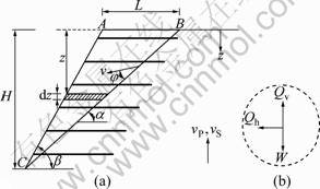
Fig.1 Model reinforced slope and failure mechanism (a), and inertia forces within failure wedge (b)
The second term of energy dissipation rate is induced as a result of soil cohesion. According to the translational mechanism (shown in Fig.1), the energy dissipation rate due to soil cohesion is computed by
![]() (3)
(3)
where H is the height of the reinforced slope. The complete formulation of the present limit analysis is presented in Section 3.
2.2 Non-associated flow rule
In the kinematic theorem of limit analysis, the magnitude of energy dissipation rate in slip surfaces depends on the soil cohesion. Zero cohesion leads to the zero dissipation rate which is the consequence of adopting the associated flow rule. With an associated flow rule, soil dilates with a constant rate of volumetric strain, and the amount of dilation is considerably higher than the observed value from the experimental results [21]. Dilation angle will always be less than the friction angle. Thus, the associated flow rule could not predict the plastic behavior of soil, comprehensively. As a result, non-associated flow rule must be applied. For a translational failure mechanism and non-associated flow rule, DRESCHER and DETOURNAY [22] modified the soil friction angle and cohesion used in the upper bound method equations as
tan �ա�=��tan �� (4)
c��=��c (5)
where ![]() and �� is the soil dilation angle.
and �� is the soil dilation angle.
The kinematic approach of limit analysis can be used by replacing the modified friction angle (�ա� ) and cohesion (c��) in the limit analysis equations. The similar methodology was previously applied by other researchers [23-25]. GANJIAN et al [25] applied Eqs.(4) and (5) to investigate the effect of non-associated flow rule on seismic stability of (unreinforced) slopes in three- dimensional space.
2.3 Pseudo-dynamic approach
In the pseudo-static method, the inertia forces are simply obtained by the product of seismic coefficients and the weight of the failure wedge. This method does not have any time-dependency and is not capable to consider the dynamic nature of seismic loading. In order to overcome this shortcoming, STEEDMAN and ZENG [26] presented a time-dependent approach called ��pseudo-dynamic approach�� to compute seismic active earth pressure on vertical retaining walls. The pseudo-dynamic approach is capable to take into account the influence of the phase and amplitude variations of horizontal and vertical earthquake accelerations with depth, velocity of primary and shear waves, and the period of lateral shaking. CHOUDHURY et al [27] applied the pseudo-dynamic approach with the help of upper bound limit analysis to evaluate the seismic stability of reinforced soil walls with cohesionless backfills. Their solution was based on the associated flow rule. Latter extensions of pseudo-dynamic approach have recently made by SHAFIEE et al [28] and GHOSH and KOLATHAYAR [29].
In the pseudo-dynamic approach, the earthquake acceleration is considered as a uniform sinusoidal function of time (t) and depth (z) with angular frequency (��) as follows:
![]() (6)
(6)
![]() (7)
(7)
where ��h(z, t) and ��v(z, t) are horizontal and vertical earthquake accelerations with amplitudes of khg and kvg at the base of slope. The parameter fa in Eqs.(6) and (7) is named the ��amplification factor�� which shows the increase in acceleration amplitude as the depth decreases.
3 Problem definition and solution
The following assumptions are made in this work to assess the seismic stability of cohesive slope of Fig.1 which obeys the non-associated flow rules:
1) Although the log-spiral failure mechanism is the most critical one [1], the translational failure mechanism is considered in this work in order to take into account the soil non-associativity in the limit analysis (see Eqs.(4) and (5)).
2) The soil is completely dry and no pore water pressure or water flow exists in the slope.
3) Both the primary wave velocity (vP) and shear wave velocity (vS) propagate through the backfill layer as a result of earthquake loading in the direction shown in Fig.1. The value of vP/vS is equal to 1.87 for most of geological materials [30].
4) The number of reinforcements is finite and all have equal lengths.
As shown in Fig.1, the slope and the translational failure surface make angles �� and ��, respectively with the horizontal plane. The weight of the failure wedge ABC is given by
![]() (8)
(8)
The mass of shaded element of thickness (dz) in Fig.1 can be expressed by
![]() (9)
(9)
The horizontal inertia force on the shaded element is equal to m(z)����h(z, t). Thus, the total horizontal inertia force Qh(t) within the failure wedge ABC can be expressed by
![]()
![]() (10)
(10)
where
![]()
![]()
![]()
and �� is the wavelength of shear waves equal to TvS and T is the period of earthquake shaking equal to 2��/��.
In the similar manner, the total vertical inertia force Qv(t) within the failure wedge ABC is given by
![]()
![]() (11)
(11)
where
![]()
![]()
![]()
and �� is the wavelength of primary waves equal to TvP. The rate of the external work due to the weight of the failure wedge as well as the inertia forces ![]() is equal to
is equal to
![]() (12)
(12)
The rate of total internal energy dissipation is equal to the summation of the internal dissipation rate due to reinforcement layers and the internal dissipation rate due to soil cohesion:
![]() (13)
(13)
Equating the rate of the external work (Eq.(12)) and the rate of total internal energy dissipation (Eq.(13)) and then, applying the non-dimensional form for total reinforcement force (as was previously used by LING et al [8]), gives
![]()
![]() (14)
(14)
Having substituted Eqs.(8), (10), and (11) into Eq.(14) and following some simplifications yields:
![]()

 (15)
(15)
where c* is the non-dimensional cohesion equal to c/(��H). It can be noticed in Eq.(15) that K is a function of ��, t/T, H/��, and H/��. Equation H/�� is the ratio of time needed for shear waves to pass through the slope height to the period of lateral shaking (T), and H/�� is the ratio of time needed for primary waves to pass through the slope height to the period of lateral shaking (T). As stated by AUSILIO et al [13], Eq.(15) provides a lower-bound solution for the reinforcement force necessary to prevent slope failure. The maximum value of K should be obtained by optimizing Eq.(15) with respect to �� and t/T.
The Eq.(15) can be rearranged to give the horizontal yield acceleration (ky) at the threshold of collapse, as follows:

![]()
![]()
![]() (16)
(16)
Equation (16) should be optimized with respect to �� and t/T to find the minimum value of horizontal acceleration that causes slope failure. In order to consider the non-associated flow rule, one should substitute the modified values of soil friction angle and cohesion, mentioned in Eqs.(4) and (5), into Eqs.(15) and (16) and then, compute the corresponding non-dimensional reinforcement force (K) and the yield acceleration (ky). The results of the present analyses are presented in the next section.
4 Results and discussion
The optimizations of the present study were carried out by Mathematica program. Results are computated for the following range of parameters:
The range of �� is 10��-45��, �� is {0, 0.5��, ��}, �� is {45��, 60��, 75��, 90��}, kh is 0.1-0.5, kv is {0, 0.5kh, kh}, c* is {0, 0.05, 0.1, 0.15, 0.2}, and fa is {1.0, 1.2, 1.4, 1.6, 1.8, 2}, presented in a combination of figures and tables.
4.1 Effect of �� and �� on required non-dimensional force
Figure 2 shows the variation of K with the soil friction angle (��) and the slope angle (��) for c*=0.05, kh= 0.2, kv=0.5kh, ��=��, and fa=1.0. The slope angle has the increasing effect while �� has decreasing effect on the non-dimensional force. The reason is due to a general rule that each parameter operating against the stability of the slope enhances the magnitude of K. Because a greater reinforcement force is required to prevent the slope failure and vice versa, steeper slopes and lower friction angles threaten the stability. Thus, the magnitude of the required non-dimensional force (K) is great for these conditions. Figure 2 also depicts that for greater values of soil friction angle, the value of K reaches to zero and for further magnitudes of ��, the required non-dimensional force attains negative values. This means that the slope can stay stable without any need to reinforcement forces. It is worthy to mention here that since the reinforcements are considered as tension member, the negative values of K which means the compressive reinforcement force must be disregarded.
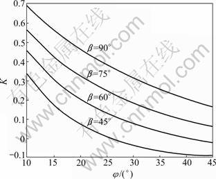
Fig.2 Variation of K with �� for c*=0.05, �� from 45�� to 90��, kh=0.2, kv=0.5kh, ��=��, fa=1.0, H/��=0.3 and H/��=0.16
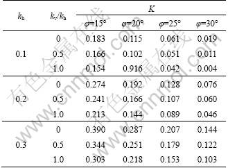
4.2 Effect of kh and kv on required non-dimensional force (K)
The influence of horizontal seismic coefficient (kh) on K for c*=0.05, ��=75��, kv=0, ��=��, and fa=1.0 is clearly shown in Fig.3. It is noticed that the magnitude of K increases with increase in kh. Table 1 demonstrates the effect of vertical seismic coefficient (kv) on non- dimensional force (K) for c*=0.10, ��=75��, ��=��, and fa= 1.0. It is seen that for customary values of horizontal seismic coefficient, the coefficient of kv has decreasing effect on K. Since the positive direction of vertical seismic coefficient is upward (shown in Fig.1), it reduces the effective weight of the failure wedge and consequently, leads to strengthening the slope. Therefore, the stability of slope can be maintained by smaller required non-dimensional force (K).
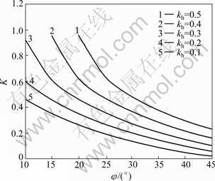
Fig.3 Effect of kh on K (c*=0.05, ��=75��, kv=0, ��=��, fa=1.0, H/��=0.3 and H/��=0.16)
Table 1 Effect of vertical seismic coefficient (kv) on K for c*=0.10, ��=75��, ��=��, H/��=0.3, H/��=0.16, and fa=1.0
4.3 Effect of non-dimensional cohesion (c*) on required non-dimensional force (K)
Figure 4 shows the effect of non-dimensional cohesion (c*) on K for ��=90��, kh=0.1, kv=0.5kh, ��=��, and fa=1.0. The magnitude of K decreases by increase in the non-dimensional cohesion. This kind of behavior is expectable, because the greater cohesion means the more stable slope which leads to lower non-dimensional force (K). The reason of negative magnitudes of K was discussed previously in Section 4.1.
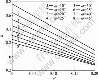
Fig.4 Variation of K with c* for ��=90��, kh=0.1, kv=0.5kh, ��=��, fa=1.0, H/��=0.3 and H/��=0.16
4.4 Effect of amplification factor (fa) on required non-dimensional force (K)
The amplification of earthquake accelerations with depth existing in the pseudo-dynamic method formulations is not taken into account in the conventional pseudo-static analysis. The variation of K with the amplification factor (fa) is shown in Fig.5 for c*=0, kh=0.1, kv=0, and ��=��. Figure 5 depicts that fa factor has increasing effect on the non-dimensional force (K). The reason is that the peak earthquake acceleration increases by increase in the magnitude of the amplification factor, which threatens the stability of the slope. Thus, the magnitude of K must be increased according to the general rule (pointed out in Section 4.1).
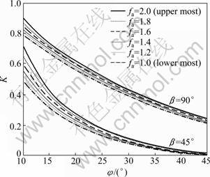
Fig.5 Effect of fa on K (c*=0, ��=45��, 90��, kh=0.1, kv=0, ��=��, H/��=0.3 and H/��=0.16)
4.5 Effect of non-associated flow rule on required non-dimensional force (K)
Figure 6(a) shows the influence of soil dilation angle (��) on K for c*=0.05, ��=45��, 75��, kh=0.3, kv=0.5kh, and fa=1.0. For ��=60�� and 90��, Fig.6(b) demonstrates the variation of K with �� for the same parameters of Fig.6(a). It is evident from these two figures that, higher dilation angle gives lower values of the non-dimensional force (K) as expected. The reason is that the factor of safety of the slope stability increases with the dilation angle [31], i.e., when dilation angle is lower, smaller reinforcement force is required to maintain the stability of slope. Figures 6(a) and 6(b) also depict that the effect of soil dilation angle is more significant for higher friction angles.
4.6 Effect of ��, �� and K on horizontal yield acceleration (ky)
The influence of soil friction angle (��), slope angle (��), and the reinforcements non-dimensional force (K) on the yield acceleration is shown in Figs.7(a) and 7(b) for c*=0.15, kv=0, ��=��, and fa=1.0. It is observed that both �� and K have increasing effect on the yield acceleration (ky). Whereas, ky decreases with increase in the slope angle (��). The reason is that the greater values of �� and K operate in the favor of the slope stability. But, the slope stability is endangered with increase in the angle ��. Thus, for greater magnitudes of �� and K and lower values of ��, a higher acceleration is required to cause the slope to yield.
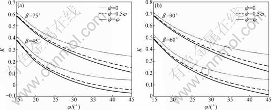
Fig.6 Effect of non-associated flow rule on K for c*=0.05, kh=0.3, kv=0.5kh, fa=1.0, H/��=0.3, H/��=0.16: (a) ��=45�� and ��=75��; (b) ��=60�� and ��=90��
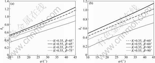
Fig.7 Variation of ky with �� for c*=0.15, kv=0, ��=��, fa=1.0, H/��=0.3, H/��=0.16: (a) ��=45�� and ��=75��; (b) ��=60�� and ��=90��
4.7 Effect of c*, ��, and kv on horizontal yield acceleration (ky)
Figure 8(a) shows the effect of the non-dimensional cohesion (c*) and dilation angle (��) on ky for ��=30��, ��= 60��, kv=0, K=0.35, and fa=1.0. Figure 8(b) presents the similar results for K=0.55. Both cohesion and dilation angle improve the shear strength of the slope soil. Thus, the yield acceleration increases with increase in magnitudes of c* and ��. Table 2 shows the influence of vertical seismic coefficient (kv) on the yield acceleration. It is observed that the effect of kv changes from increasing to decreasing as the friction angle exceeds 15��, which has not been mentioned in the earlier investigations.
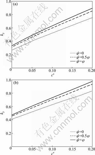
Fig.8 Effect of c* and non-associated flow rule on ky for ��=30��, ��=60��, kv=0, fa=1.0, H/��=0.3, H/��=0.16: (a) K=0.35; (b) K= 0.55
5 Comparisons
Figure 9 shows the variation of K with �� for c*=0, kh=0.2, kv=0, and fa=1.0 obtained by the present study compared with the results of LING et al [8], MICHALOWSKI [12], AUSILIO et al [13] and NOURI et al [10] for the same values of parameters. It is observed that the curve corresponding to the ��=�� case generally presents the lowermost values for K. But, MICHALOWSKI [12] solution (considering logarithmic spiral mechanism) gives the highest result especially for lower friction angles. Figure 9 also depicts that the results of LING et al [8] analysis (considering tieback mechanism) and AUSILIO et al [13] kinematic solution (considering planar failure surface) are in a good agreement with the ��=0.5�� case of the present study.
Table 2 Effect of kv on horizontal yield acceleration (ky) for c*=0, ��=45��, K=0.35, ��=��, H/��=0.3, H/��=0.16 and fa=1.0
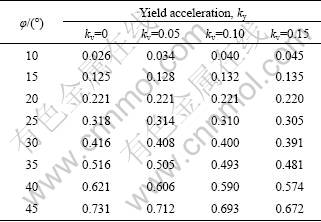
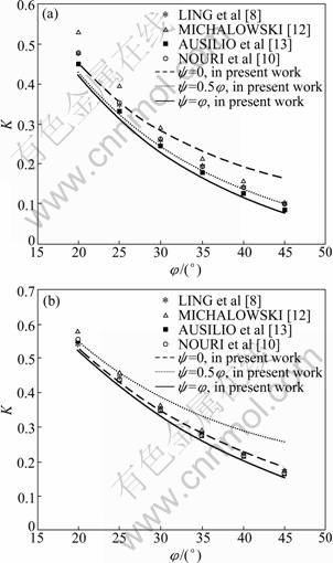
Fig.9 Comparison of variation of K with �� for c*=0, kh=0.2, and kv=0 obtained by present study with earlier investigations: (a) ��=60��; (b) ��=75��
Figure 10 shows the variation of yield acceleration (ky) with �� obtained from the present study with c*= 0, ��=45��, kv=0, K=0.35, and fa=1.0 compared with the results of AUSILIO et al [13]. It is observed that the solution of AUSILIO et al [13] is closest to the ��=0.5�� case of the present work. Whereas, for a zero dilation angle, the yield acceleration is lower. The effect of soil non-associativity is more significant for higher friction angle. Therefore, more attention should be paid to the soil dilation angle for these cases.
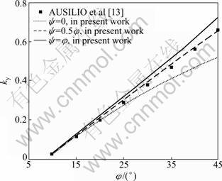
Fig.10 Comparison of variation of ky with �� for c*=0, ��=45��, kv=0, and K=0.35 obtained by present study with earlier investigations
6 Conclusions
The kinematic approach of limit analysis in conjunction with pseudo-dynamic method was used to assess the seismic stability of reinforced cohesive slopes. The effect of non-associated flow rule was considered in this work. The following conclusions can be derived from the present computations:
1) Based on a general rule, each parameter which operates against the stability of the slope enhances the magnitude of the non-dimensional reinforcement force (K). A greater reinforcement force is required to prevent the slope failure and vice versa. Therefore, parameters such as soil friction angle (��), cohesion (c), dilation angle (��), and upward vertical seismic coefficient (kv) have decreasing effect on K, whereas the slope angle (��), horizontal seismic coefficient (kh), and amplification factor (fa) have increasing effect on K.
2) The horizontal yield acceleration (ky) increases with increase in ��, c, ��, and K. The reason is that these parameters operate in the favor of the slope stability. Thus, higher acceleration is required to cause the slope to yield. But, the slope stability is endangered with increase in the slope angle (��). Therefore, the �� angle has decreasing effect on the yield acceleration.
References
[1] JEWELL R A. Revised design charts for steep reinforced slopes: Reinforced embankments, theory and practice [M]. London: Thomas Telford, 1990.
[2] SRBULOV M. Analysis of stability of geogrid reinforced steep slopes and retaining walls [J]. Computers and Geotechnics, 2001, 28(4): 255-268.
[3] DE BUHAN P, MANGIAVACCHI R, NOVA R, PELLEGRINI G, SALENCON J. Yield design of reinforced earth walls by a homogenization method [J]. Geotechnique, 1989, 39 (2): 189-201.
[4] PORBAHA A, ZHAO A, KOBAYASHI M, KISHIDA T. Upper bound estimate of scaled reinforced soil retaining walls [J]. Geotextiles and Geomembranes, 2000, 18(6): 403 -413.
[5] SINGH D N, BASUDHAR P K. Determination of the optimal lower-bound-bearing capacity of reinforced soil-retaining walls by using finite elements and non-linear programming [J]. Geotextiles and Geomembranes, 1993, 12(7): 665-686.
[6] MICHALOWSKI R L, ZHAO A. Continuum versus structural approach to stability of reinforced soil [J]. ASCE Journal of Geotechnical Engineering, 1995, 121(2): 152-162.
[7] ZHAO A, MONTANELLI F, RIMOLDI P. Design of reinforced foundations by the slip-line method [C]// Proceedings of the Earth Reinforcement. Ochiai Japan, 1996: 709-714.
[8] LING H I, LESHCHINSKY D, PERRY E B. Seismic design and performance of geosynthetic-reinforced soil structures [J]. Geotechnique, 1997, 47(5): 933-952.
[9] LING H I, LESHCHINSKY D. Effect of vertical acceleration on seismic design of geosynthetic-reinforced soil structure [J]. Geotechnique, 1998, 48(3): 347-373.
[10] NOURI H, FAKHER A, JONES C J F P. Development of horizontal slice method for seismic stability analysis of reinforced slopes and walls [J]. Geotextiles and Geomembranes, 2006, 24(3): 175-187.
[11] JAHANANDISH M, KESHAVARZ A. Seismic bearing capacity of foundations on reinforced soil slopes [J]. Geotextiles and Geomembranes, 2005, 23(1): 1-25.
[12] MICHALOWSKI R L. Soil reinforcement for seismic design of geotechnical structures [J]. Computers and Geotechnics, 1998, 23(1): 1-17.
[13] AUSILIO E, CONTE E, DENTE G. Seismic stability analysis of reinforced slopes [J]. Soil Dynamics and Earthquake Engineering, 2000, 19(3): 159-172.
[14] HUANG C C, HORNG J C, CHARNG J J. Seismic stability of reinforced slopes: failure mechanisms and displacements [J]. Geosynthetics International, 2008, 15(5): 333-349.
[15] HU Y, ZHANG G, ZHANG J M, LEE C F. Centrifuge modeling of geotextile-reinforced cohesive slopes [J]. Geotextiles and Geomembranes, 2010, 28(1): 12-22.
[16] BATHURST R J, VLACHOPOULOS N, WALTERS D L, BURGESS P G, ALLEN T M. The influence of facing stiffness on the performance of two geosynthetic reinforced soil retaining walls [J]. Canadian Geotechnical Journal, 2006, 43(12): 1225-1237.
[17] MATSUO O, TSUTSUMI T, YOKOYAMA K, SAITO Y. Shaking table tests and analysis of geosynthetic-reinforced soil retaining walls [J]. Geosynthetics International, 1998, 5(1 2): 97-126.
[18] ROWE R K, SODERMAN K L. An approximate method for estimating the stability of geotextile reinforced embankments [J]. Canadian Geotechnical Journal, 1985, 22(3): 392-398.
[19] LING H I, CARDANY C P, SUN L X, HASHIMOTO H. Finite element study of a geosynthetic-reinforced soil retaining wall with concrete-block facing [J]. Geosynthetics International, 2000, 7(2): 137-162.
[20] SAWICKI A, LESNIEWSKA D. Stability of fabric reinforced cohesive soil slopes [J]. Geotextiles and Geomembranes, 1991, 10(2): 125-146.
[21] MANOHARAN N, DASGUPTA S P. Bearing capacity of surface footings by finite elements [J]. Computers and Structures, 1995, 54(4): 563-586.
[22] DRESCHER A, DETOURNAY E. Limit load in translational failure mechanisms for associative and non-associative materials [J]. Geotechnique, 1993, 43(3): 443-456.
[23] YANG X L, GUO N Z, ZHAO L H, ZOU J F. Influences of nonassociated flow rules on seismic bearing capacity factors of strip footing on soil slope by energy dissipation method [J]. Journal of Central South University of Technology, 2007, 14(6): 842-847.
[24] YANG X L, HUANG F. Slope stability analysis considering joined influences of nonlinearity and dilation [J]. Journal of Central South University of Technology, 2009, 16(2): 292-296.
[25] GANJIAN N, ASKARI F, FARZANEH O. Influences of nonassociated flow rules on three-dimensional seismic stability of loaded slopes [J]. Journal of Central South University of Technology, 2010, 17(3): 603-611.
[26] STEEDMAN R S, ZENG X. The influence of phase on the calculation of pseudo-static earth pressure on a retaining wall [J]. Geotechnique, 1990, 40(1): 103-112.
[27] CHOUDHURY D, NIMBALKAR S S, MANDAL J N. External stability of reinforced soil walls under seismic conditions [J]. Geosynthetics International, 2007, 14(4): 211-218.
[28] SHAFIEE A H, ESKANDARINEJAD A, JAHANANDISH M. Seismic passive earth thrust on retaining walls with cohesive backfills using pseudo-dynamic approach [J]. Geotech Geol Eng, 2010, 28(4): 525-531.
[29] GHOSH P, KOLATHAYAR S. Seismic passive earth pressure behind non vertical wall with composite failure mechanism: Pseudo-dynamic approach [J]. Geotech Geol Eng, 2010, DOI: 10.1007/s10706-010-9382-9.
[30] DAS B M. Principles of soil dynamics [M]. Boston: PWS-KENT Publishing Company, 1993.
[31] WANG Y J, YIN J H, LEE C F. The influence of a non-associated flow rule on the calculation of the factor of safety of soil slopes [J]. Int J Numer Anal Meth Geomech, 2001, 25(13): 1351-1359.
(Edited by DENG L��-xiang)
Received date: 2011-02-21; Accepted date: 2011-06-27
Corresponding author: A. H. Shafiee, PhD Candidate; Tel: +98-711-6265149; E-mail: amshafiee@shirazu.ac.ir
Abstract: The required reinforcement force to prevent instability and the yield acceleration of reinforced slopes are computed under seismic loading by applying the kinematic approach of limit analysis in conjunction with the pseudo-dynamic method for a wide range of soil cohesion, friction angle, dilation angle and horizontal and vertical seismic coefficients. Each parameter threatening the stability of the slope enhances the magnitude of the required reinforcement force and vice versa. Moreover, the yield acceleration increases with the increase in soil shear strength parameters but decreases with the increase in the slope angle. The comparison of the present work with some of the available solutions in the literatures shows a reasonable agreement.
