
J. Cent. South Univ. (2017) 24: 1369-1378
DOI: 10.1007/s11771-017-3541-6

Dynamic matrix predictive control for a hydraulic looper system in hot strip mills
YIN Fang-chen(������), SUN Jie(���), PENG Wen(����), WANG Hong-yu(������),
YANG Jing(�), ZHANG Dian-hua(�ŵ)
State Key Laboratory of Rolling and Automation (Northeastern University), Shenyang 110819, China
 Central South University Press and Springer-Verlag Berlin Heidelberg 2017
Abstract:
Controlling the looper height and strip tension is important in hot strip mills because these variables affect both the strip quality and strip threading. Many researchers have proposed and applied a variety of control schemes for this problem, but the increasingly strict market demand for strip quality requires further improvements. This work describes a dynamic matrix predictive control (DMC) strategy that realizes the optimal control of a hydraulic looper multivariable system. Simulation experiments for a traditional controller and the proposed DMC controller were conducted using MATLAB/Simulink software. The simulation results show that both controllers acquire good control effects with model matching. However, when the model is mismatched, the traditional controller produces an overshoot of 32.4% and a rising time of up to 2120.2 ms, which is unacceptable in a hydraulic looper system. The DMC controller restricts the overshoot to less than 0.08%, and the rising time is less than 48.6 ms in all cases.
Key words:
hot strip mill; hydraulic looper system; mathematical model; dynamic matrix predictive control��
1 Introduction
A hot strip mill rolls cast steel slabs into thin sheets [1]. A typical hot strip mill facility consists of, the following units: reheat furnace, roughing mill, transfer table, coilbox, crop shear, finishing mill, runout table and coiler [2, 3]. Bars of around 250 mm thickness are reheated to a temperature of approximately 1200 ��C in the reheat furnace. In the roughing mill, the reheated slabs are reduced to a thickness of 25-50 mm. The resulting sheet bar is then transported to the finishing mill, where it is further reduced to the final thickness 0.8-20 mm.
During the hot strip rolling process, the looper angle and strip tension control play an important role in both the dimensional quality and mass flow of the strips [4, 5]. The control target is to keep the looper angle and strip tension as close to the desired values as possible. For the past three decades, hydraulic loopers have been widely used in the steel industry because of their fast transient response and high stability and precision. However, there are several disadvantages, such as significant system parameter uncertainties and disturbances, and a nonlinear hydraulic servo system, which complicates the design of the hydraulic looper control system [6, 7]. A number of scholars have investigated solutions to this problem. SHARIFI [8] presented the neuro-fuzzy control system that gives the looper system a fast response time. TONG et al [9] studied the looper system controller with a sliding-mode, variable-structure strategy to enhance the looper system��s robustness. TIMOTHY et al [10] proposed a fully nonlinear output feedback controller based on a recursive nonlinear method to deal with the unmodeled dynamics and large parameter variations of looper system. Model predictive control, which is well known for its robustness, has been used to design the controller in many rolling fields. For instance, SCHUURMANS and JONES [11] suggested an MPC controller for mass flow control design by taking account of constraints, and SUN et al [12] designed a controller with model predictive control theory for hydraulic roll gap control system. In this work, for hydraulic looper system, the interaction between looper height and strip tension is considered and a dynamic matrix predictive control (DMC) strategy is realized by solving a matrix equation. The resulting controller can be applied in both the looper height and strip tension loops based on the coupled transfer function model of the system.
2 Model of hydraulic looper system
In this section, we give an overview of the looper height and strip tension model that is used to analyze hydraulic looper systems. The model description closely follows that in Ref. [1], and forms the background of the control problem. Figure 1 shows the geometry of the looper and strip for the adjacent stands of seven rolling stands in the hot strip finishing mill.
In Fig. 1, �� is the looper angle; L is the distance between two stands; L2 is the distance between the actual pass line and the looper pivot; L3 is the distance between stand i and the looper pivot; r is the radius of the looper roll; �� is the angle between the looper power arm and the movable arm; f is the angle between the hydraulic cylinder and the vertical direction; �� is the angle between the tangential direction of the looper power arm and the hydraulic cylinder; vi+1 is the roll line speed at the (i+1)th stand; vi is the roll line speed at the ith stand;  is the delivery speed of the strip at the ith stand; and
  is the entry speed at the (i+1)th stand.
2.1 Model of strip tension system
The strip tension increment ���� is approximately proportional to both the elastic modulus and the strip stretch according to the following equation:
 (1)
(1)
where ��L is the accumulated loop length; E is the elastic modulus; ����v is the looper variation caused by changes in speed.
According to the geometrical relationship in Fig. 1, the relationship between the looper height and looper angle is:
 (2)
(2)
where  ;
;
and ����v can be calculated as
 (3)
(3)
for
 (4)
(4)
where ��i+1 is the backward slip at the (i+1)th stand and fi is the forward slip at the ith stand.
Substituting Eqs. (2) and (4) into Eq. (1), the model is approximately linearized using a Taylor expansion, which gives

 (5)
(5)
2.2 Model of looper height system
Applying Newton��s law of motion to the hydraulic looper system, the following equation can be obtained:
 (6)
(6)
where M is the output torque of the looper hydraulic cylinder; Fload is the total load acting on the looper; and L1 is the length of the movable arm.
Fload is composed of three main components: the strip tension, F��, the total force of the strip weight and looper weight, Fw, and the strip bending force, Fb:
 (7)
(7)
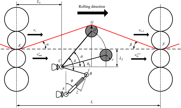
Fig. 1 Schematic drawing of a hydraulic looper system
The above three quantities are modeled as follows.
F�� can be evaluated as
 (8)
(8)
where W is the strip width and H is the strip exit thickness.
Fw can be evaluated as
 (9)
(9)
where WR is the looper weight and WL is the looper arm weight.
Fb can be evaluated as
 (10)
(10)
Substituting Eq. (7) into Eq. (6), the model is approximately linearized using a Taylor expansion, which gives
 (11)
(11)
2.3 Actuator modeling
The actuator of the hydraulic looper is a hydraulic cylinder that is driven by a servo valve. The natural frequency of the hydraulic cylinder is higher than 20 Hz [13, 14]. The transfer function of the servo valve can thus be described as
 (12)
(12)
where Qv is the flow rate of the servo valve; i is the control current of the servo valve; Ksv is the flow gain coefficient of the servo valve; ��sv is the natural frequency; and ��sv is a damping coefficient.
Based on the balance equation of the hydraulic cylinder and the load force, and neglecting the damping coefficient and leakage coefficient, the transfer function of the hydraulic cylinder Gs(s) can be obtained as
 (13)
(13)
where F is the thrust of the hydraulic cylinder; A is the effective area of the hydraulic cylinder piston; ��e is the elastic modulus of hydraulic oil; K is the equivalent load stiffness; Me is the equivalent quality of the load; and Vt is the maximum volume of the cylinder cavity that is under pressure.
The transfer function of the rolling mill��s main drive system Gv(s) can be described by a first-order system:
 (14)
(14)
where Tv is the time constant.
2.4 Transfer function model of hydraulic looper system
A block diagram of the linearized model is given in Fig. 2. The manipulated variables are the roll velocity v and the control current i. The controlled variables are the interstand tension �� and the looper angle ��.
The coupling transfer function model can be obtained by a Laplace transform as
 (15)
(15)
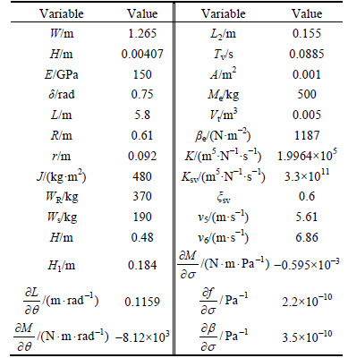
The No. 5 stand, No. 6 stand, and No. 5 hydraulic looper in the 1700 mm hot strip mill were taken as the research objects in a simulation. The initial value of the looper angle was set to 0.296 rad and the initial value of the strip tension was set to 5 MPa. The simulation parameters are given in Table 1.
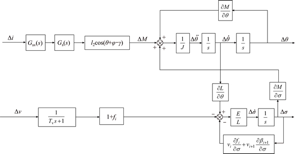
Fig. 2 Linear model of a hydraulic looper system
Table 1 Simulation parameters of hydraulic looper system
Using the above data, the coupled transfer functions can be obtained as


 (16)
(16)


 (17)
(17)


 (18)
(18)


 (19)
(19)
3 Looper control architecture
3.1 Traditional PI control scheme
The classical control scheme for the looper is based on a proportional-integral (PI) control architecture such as that depicted in Fig. 3. The strip tension error ���� is controlled by a PI regulator that acts, with a trim, on the reference control current iref of the servo valve. The looper angle deviation ���� is regulated by a control loop based on a PI controller that acts, with a trim, on the reference speed vref [15, 16].
The above PI control architecture is widely used, mainly because of its simplicity. However, this control scheme can perform very poorly in the presence of disturbances and modeling uncertainties. For example, if the looper angle cannot be maintained near the desired value, the dynamic equilibrium of the metal mass flow will be broken. Hence, in the following, a dynamic matrix control scheme will be proposed.
3.2 Dynamic matrix control: a brief summary
DMC is a predictive control algorithm based on a step response model. It can use online optimization based on feedback correction to replace the traditional optimum control [17]. The DMC optimum algorithm is composed of three parts: model prediction, online optimization and feedback correction [18, 19].
The looper height control is taken as an example. The looper height control system based on the DMC controller can be described as shown in Fig. 4.
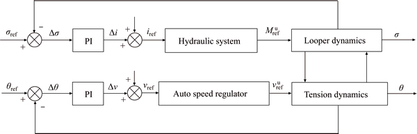
Fig. 3 Traditional PI control structure of a hydraulic looper system
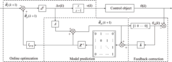
Fig. 4 Diagram of looper height control system based on DMC
1) Model prediction
It is assumed that the roll linear speed v is the control input, the actual looper angle �� is the control output, and the unit-step sampling data of the controlled object are [a1, a2, ��].
According to the principle of superposition, the output angle  at time k+1 can be predicted as
 (20)
(20)
where

 and
and  is a dynamic matrix.
2) On-line optimization
The DMC controller uses the optimization performance index to adjust the control strategy. The optimization performance index at time k is defined as

 (21)
(21)
where
 is the expected looper angle;
 is the error weight matrix;
 is the control weight matrix; qi are error weight coefficients; rj are control weight coefficients; p is the optimization horizon length; and m is the control horizon length.
3) Feedback correction
The actual looper angle is introduced into the DMC controller to correct the predicted value because uncertainty will result in a model mismatch. Thus:
 (22)
(22)
where  is the predicted looper angle after error correction;
  is the error correction vector; ��m(k) is the predicted looper angle; and ��(k) is the actual looper angle.
Finally, the DMC optimization strategy is formulated in terms of minimizing the roll line speed increment ��v(k).
3.3 Application of DMC technique in a hydraulic looper control system
The hydraulic looper system is decomposed into two subsystems of double inputs and a single output. It is assumed that the step response matrix describing the effect of the roll linear speed on the looper angle is  and the step response matrix describing the effect of the control current on the looper angle is
  . The predicted output looper angle
  is then given by

 (23)
(23)
where  is the error correction vector and
  is the prediction error.
The optimization performance index of a closed loop for the looper height is defined as

 (24)
(24)
where  is the expected looper angle;
  is the error weight matrix and
  is the control weight matrix.
To minimize the performance index function, we set  The optimal control speed increment series can then be obtained as

 (25)
(25)
The optimization performance index of a closed loop for the strip tension is defined as

 (26)
(26)
where  is the predicted output value of the strip tension and
  is the expected strip tension.
It is assumed that the step response matrix describing the effect of the roll linear speed on strip tension is  and the step response matrix describing the effect of the control current on strip tension is
  The optimal control current increment series can then be obtained as

 (27)
(27)
Applying a matrix inversion process to Eqs. (25) and (27),  and
and  can be rewritten in the form:
 (28)
(28)
 (29)
(29)
where 


Applying a matrix inversion process to Eqs. (28) and (29) based on a recursive algorithm,  and can be obtained as
 (30)
(30)
 (31)
(31)
The structure of the DMC decoupling control system is shown in Fig. 5.
In the designed DMC controller, the performance index functions of the looper angle and strip tension are given independently. Thus, the decoupling control and predictive optimal control can be realized by adjusting the DMC controller parameters, i.e., the prediction horizon of the looper angle p��, the prediction horizon of the strip tension p��, the control horizon of the roll linear speed mv, and the control horizon of the control current mi.
4 Simulation experiments
Using the working and control principles of a hydraulic looper in a hot rolling mill, the control effects of the PI and DMC controllers were compared using MATLAB/Simulink software. The parameters of the PI and DMC controllers used in these simulations are listed in Table 1.
4.1 Comparison of step response
The simulations were carried out as follows. A step testing signal with amplitude of 0.02 rad was added to the initial value of the looper angle at t=1 s. The simulation results are shown in Fig. 6.
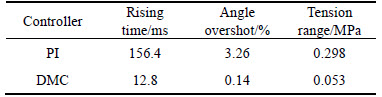
The dynamic characteristic parameters of the PI and DMC controllers were calculated, and the results are presented in Table 2.
In a hydraulic looper system, the rising time is required to be less than 200 ms, and the overshoot must be less than 10%. As shown in the above table, the PI controller gives a rising time of 156.4 ms and an overshoot angle of 3.26%. The proposed DMC controller produces a lower rising time of just 12.8 ms, and an overshoot angle of only 0.14%. The dynamic characteristic parameters of both controllers are acceptable in a hydraulic looper system. Furthermore, because of the decoupling technique in the DMC controller, the tension fluctuation is 0.053 MPa, which is much smaller than that of the PI controller.
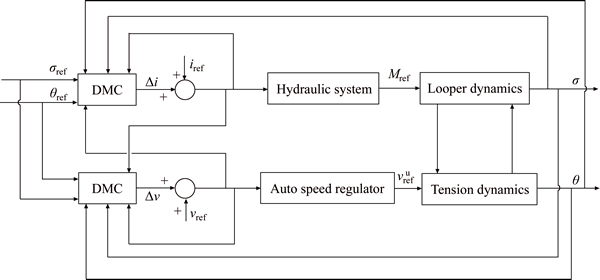
Fig. 5 DMC decoupling control structure of a hydraulic looper system
Table 1 List of controller parameters

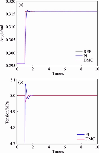
Fig. 6 Response curves of looper angle step disturbance
Table 2 Comparison of dynamic characteristics
4.2 Comparison of disturbance rejection performance
In an actual hot strip rolling process, there is a mutual interaction between the automatic gauge control system and the hydraulic looper control system. In the hydraulic looper system, the main disturbance comes from changes in mass flow. We added changes in the roll gap, regarded as the disturbance signals, to the strip tension closed loop. Additionally, variations in strip thickness and temperature, approximated by Gaussian noise, were added to the simulation.
Various amplitudes of disturbance ��Sa with frequency of 0.5 Hz were added to the initial value of the roll gap. The simulation results are shown in Figs. 7 and 8.
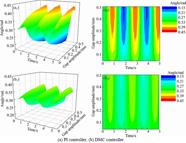
Fig. 7 Response curves of looper angle with sinusoidal roll gap disturbance:
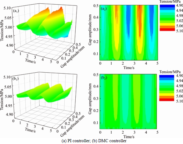
Fig. 8 Response curves of strip tension with sinusoidal roll gap disturbance:
The dynamic characteristic parameters of the PI and DMC controller were again calculated, and the results are presented in Table 3.
Table 3 Dynamic characteristic parameters achieved with sinusoidal roll gap disturbance
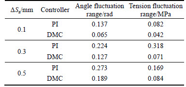
As shown in the above the simulation results, when the roll gap disturbance ��Sa increases, the angle fluctuation given by the PI controller range reaches 0.273 rad and the tension fluctuation range reaches 0.169 MPa. Smaller roll gap disturbances result in an angle fluctuation range of 0.137 rad and a tension fluctuation range of 0.082 MPa. In all cases, the dynamic characteristic parameters of the PI controller are worse than those of the DMC controller.
4.3 Simulation with varying rolling process parameters
In actual hot strip mill production, various strip specifications are rolled. Thus, the hydraulic looper system must be robust to ensure the quality of strips. In this simulation, the effect of different cross sectional areas was investigated under both the PI and DMC controllers.
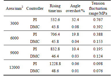
A step disturbance with amplitude of 0.02 rad was added to the initial value of the looper angle at t=1 s. The simulation results are shown in Figs. 9, and 10 and Table 4. As the cross sectional areas become bigger, the overshoot angle of both controllers remains fairly good, although the rising time of the PI controller increases to 1228.8 ms, which is unacceptable in a hydraulic looper system. In contrast, the rising time of the DMC controller remains below 50 ms. When the cross sectional areas of the strip become smaller, the rising time of both controllers decreases. However, for the PI controller, the minimum rising time is 532.6 ms and the overshoot angle is 32.4%, which do not meet the dynamic response requirements of a hydraulic looper system. However, the DMC controller achieves a rising time of just 43.8 ms and an overshoot angle of 0.08%. These levels are acceptable for hydraulic looper systems. Additionally, the tension overshoot of the DMC controller is less than 0.4 MPa in all cases, which is less than that of the PI controller.
From the above results, it is clear that good control effects can be achieved by both controllers with model matching. When the system is disturbed or the rolling process parameters change, the disturbance rejection and robustness of the PI controller becomes degraded, and large overshoots or long rising times appear. However, the hydraulic looper control system based on the proposed DMC controller is relatively insensitive to disturbances and rolling process parameter changes, exhibiting strong disturbance rejection and robustness.
Table 4 Dynamic characteristic parameters achieved with various cross-sectional areas
5 Conclusions
1) Based on the generation mechanism of strip tension and the force conditions of a hydraulic looper, a dynamical mathematical model of a hydraulic looper system has been established. The DMC controller that allows predictive optimal control was designed for the established model.
2) Simulation platforms for the DMC and PI control systems were developed using MATLAB/Simulink. A comparison of the step response and disturbance rejection performance with model matching was carried out. The simulation results showed that, under the condition that the disturbance comes from roll gap, the DMC controller can achieve better dynamic performance with higher levels of control.
3) Under the condition that the controller parameters remain constant, comparison experiments with different cross-sectional areas of strip were carried out. The simulation results showed that the overshoot and rising time of the PI controller increase beyond the levels accepted by hydraulic looper systems. In the case of the DMC controller, the overshoot angle remained less than 0.15%, and the rising time was less than 50 ms. The tension fluctuation range was less than 0.4 MPa in all scenarios. Thus, the control performance of the proposed DMC controller is better than the PI controller.
References
[1] SANSAL K Y, HUANG B, FORBES J F. Dynamics and variance control of hot mill loopers [J]. Control Engineering Practice, 2008, 16(1): 89-100.
[2] CHOI I S, ROSSITER J A, FLEMING P J. Looper and tension control in hot rolling mills: A survey [J]. Journal of Process Control,2007, 17(6): 509-521.
[3] KAZUYA A, KAZUIRO Y, TAKASHI K, NOBUAKI N. Hot strip mill tension-looper control based on decentralization and coordination [J]. Control Engineering Practice, 2000, 8(3): 337-344.
[4] LI Bo-qun, FU Jian, ZHANG Rui-cheng, SUN Yi-kang. The decoupling control for the loopers�� height and tension system in hot strip finishing mill [J]. Journal of University of Science and Technology Beijing, 2007, 27(5): 596-599. (in Chinese)
[5] LI Bo-qun, ZHANG Ke-jun, FU Jian, SUN Yi-kang. Adaptive neural network decoupling control for the loopers�� height and tension system [J]. Control and Decision, 2006, 21(1): 46-50. (in Chinese)
[6] RICCARDO F, FRANCESCO A C, THOMAS P. Friction compensation in the interstand looper of hot strip mills: a sliding- mode control approach [J]. Control Engineering Practice, 2008, 16(2): 214-224.
[7] TAO Gui-lin, LIU Chao. Accurate calculation of loop tension moment of hot strip mill [J]. Steel Rolling, 2014, 31(3): 20-22. (in Chinese)
[8] SHARIFI F J. A neuro-fuzzy system for looper tension control in rolling mills [J]. Control Engineering Practice, 2005, 13(1): 1-13.
[9] TONG Chao-nan, WU Yan-kun, LIU Lei-ming, LI Jiang-yun. Modeling and integral variable structure control of hydraulic looper multivariable system [J]. Acta Automatica Sinica, 2008, 34(10): 1305-1312. (in Chinese)
[10] TIMOTHY H, YU A J, DAVID J C, DAVID H B. Controller design for hot strip finishing mills [J]. IEEE Transactions on Control Systems Technology, 1998, 6(2): 208-219.
[11] SCHUURMANS J, JONES T. Control of mass flow in a hot strip mill using model predictive control [C]// Proceedings of the 2002 IEEE International Conference on Control Applications. Princeton: IEEE, 2002: 379-384
[12] SUN Jie, CHEN Shu-zong, HAN Huan-huan, CHEN Xing-hua, CHEN Qiu-jie, ZHANG Dian-hua. Identification and optimization for hydraulic roll gap control in strip rolling mill [J]. Journal of Central South University, 2015, 22(6): 2183-2191.
[13] CHEN Chun-ta, RENN J C, YAN Zong-yuan. Experimental identification of inertial and friction parameters for electro-hydraulic motion simulators [J]. Mechatronics, 2011, 21(1): 1-10.
[14] WANG Yan, ZHANG Ze, QIN Xu-qing. Modeling and control for hydraulic transmission of unmanned ground vehicle [J]. Journal of Central South University, 2014, 21(1): 124-129.
[15] JOHN P, MARWAN A S. Improvement in control of the tandem hot Strip Mill [J]. IEEE Transactions on Industrial Applications, 2013, 49(5): 1962-1970.
[16] JEONG J C, WAN K H, JONG S K. A self-tuning PI control system design for the flatness of hot strip in finishing mill processes [J]. KSME International Journal, 2004, 18(3): 379-387.
[17] PEDRO R, EFSTRATIOS N P. A dynamic programming based approach for explicit model predictive control of hybrid systems [J]. Computers and Chemical Engineering, 2015, 72: 126-144.
[18] CAMACHO E F, RAMIREZ D R, LIMON D, MUNOZ P, ALAMO T. Model predictive control techniques for hybrid systems [J]. Annual Reviews in Control, 2010, 34(2): 21-31.
[19] SU Bai-li, CHEN Zeng-qiang, YUAN Zhu-zhi. Multivariable decoupling predictive control with input constraints and its application on chemical process [J]. Chinese Journal of Chemical Engineering, 2006, 14(2): 216-221.
(Edited by YANG Hua)
Cite this article as:
YIN Fang-chen, SUN Jie, PENG Wen, WANG Hong-yu, YANG Jing, ZHANG Dian-hua. Dynamic matrix predictive control for a hydraulic looper system in hot strip mills [J]. Journal of Central South University, 2017, 24(6): 1369-1378.
DOI:https://dx.doi.org/10.1007/s11771-017-3541-6Foundation item: Project(N160704004) supported by the Fundamental Research Funds for the Central Universities, China; Project(20131033) supported by the PhD Start-up Fund of Natural Science Foundation of Liaoning Province, China
Received date: 2015-11-16; Accepted date: 2016-03-17
Corresponding author: SUN Jie, Associate Professor, PhD; Tel: +86-24-83690361; E-mail: sunjie@ral.neu.edu.cn
Abstract: Controlling the looper height and strip tension is important in hot strip mills because these variables affect both the strip quality and strip threading. Many researchers have proposed and applied a variety of control schemes for this problem, but the increasingly strict market demand for strip quality requires further improvements. This work describes a dynamic matrix predictive control (DMC) strategy that realizes the optimal control of a hydraulic looper multivariable system. Simulation experiments for a traditional controller and the proposed DMC controller were conducted using MATLAB/Simulink software. The simulation results show that both controllers acquire good control effects with model matching. However, when the model is mismatched, the traditional controller produces an overshoot of 32.4% and a rising time of up to 2120.2 ms, which is unacceptable in a hydraulic looper system. The DMC controller restricts the overshoot to less than 0.08%, and the rising time is less than 48.6 ms in all cases.
