
Trans. Nonferrous Met. Soc. China 29(2019) 950-963
Simulation and experimental verification of interfacial interactions in compound squeeze cast Al/Al-Cu macrocomposite bimetal
Mohammad Hossein BABAEE1, Behzad NIROUMAND1, Ali MALEKI2, Meysam LASHANI ZAND1
1. Department of Materials Engineering, Isfahan University of Technology, Isfahan 84156-83111, Iran;
2. Department of Mechanical Engineering, Isfahan University of Technology, Isfahan 84156-83111, Iran
Received 16 July 2018; accepted 19 December 2018
Abstract:
The objective of this work was to investigate the thermal and mechanical interactions between the two components of a compound squeeze cast macrocomposite bimetal. First, an Al/Al-4.5wt.%Cu macrocomposite bimetal was fabricated by compound squeeze casting process. Then, heat transfer, solidification and distribution of the generated stresses along the interface region of the bimetal were analyzed using Thermo-Calc, ProCAST and ANSYS softwares, and structure, copper distribution and microhardness changes across the interface of the bimetal were studied. The results showed no noticeable change in the structure of the Al-4.5wt.%Cu insert and no obvious micromixing and diffusion of copper across the interface. Simulation results were in good agreement with the experimental ones only when an equivalent oxide layer at the interface was defined and its effect on heat transfer was considered. This layer caused up to 50% decrease in local liquid fraction formed on the surface of the insert. Simulation of the generated stresses showed a uniformly distributed stress along the interface which was significantly lower than the compressive strength of the oxide layer, resulting in its good stability during the fabrication process. It was postulated that this continuous oxide layer not only acted as a thermal barrier but prevented the direct metal-metal contact along the interface as well.
Key words:
Al/Al-Cu macrocomposite; bimetal; compound squeeze casting; simulation; interface; stress;
1 Introduction
Aluminum and its alloys enjoy unique properties such as high thermal and electrical conductivity, excellent resistance to corrosion and oxidation, high specific strength and good castability [1]. Aluminum is used in producing a wide variety of lightweight constructions due to its low density and plays a significant role in weight saving of industrial parts as well as decreasing fuel consumption and environmental contamination [1-3]. There are many engineering and industrial demands; however, which cannot be satisfied using monolithic materials. In recent decades, the idea of producing multi-material structures, i.e. bimetallic materials, has been seriously pursued to compensate these limitations [2,4]. Bimetals are macrocomposite materials intended to provide an optimized combination of physical, mechanical and chemical properties which are not achievable by any of the individual components separately [2,4-6].
Bimetals are extensively used for different industrial applications such as corrosion resistant and wear resistant applications, tools, antifriction parts, deep extrusion and thermostats [7]. Most common metals and alloys such as steel, cast iron, copper, aluminum and magnesium alloys can be utilized to produce bimetals [2,8]. Considerable attention has been paid to fabricate aluminum-aluminum bimetals in recent years. The main routes to fabricate aluminum-aluminum bimetallic parts can be divided into three different categories including solid-solid, solid-liquid and liquid- liquid bonding methods [6,8,9]. Compound casting is a promising solid-liquid manufacturing process used for fabrication of relatively complex bimetallic joints without any dimensional limitations. In this process, interactions between a liquid metal and a solid part (insert), of usually different composition, fixed in a die can lead to formation of bimetallic components [2,8,10].
Studies on compound casting of aluminum alloys are still limited [2]. It seems that the presence of a stable oxide layer, i.e. Al2O3, on the surface of aluminum inserts is the main reason that only a few investigations have been reported so far on successful compound casting of aluminum [8,11,12]. This high melting point (about 2000 ��C) layer is thermodynamically stable. In addition, it has low wetting tendency in contact with most molten aluminum alloys. Therefore, it hinders the diffusion through the interface of the bimetals after compound casting [8,13]. One solution suggested in most recent studies is to remove this detrimental layer and replace it by a reactive metallic coating, usually zinc layer. This metallic layer must be thick enough to inhibit re-oxidation of aluminum surface. It also must have low melting point, high solubility in aluminum at elevated temperatures and adequate wettability in contact with molten aluminum alloys. The coating must be readily melted and dissolved during the casting process in order to form proper metallurgical bonding and a continuous transition zone between the two components [8,11-18].
This paper focuses on simulation of thermal and mechanical interactions between the two components of an Al/Al-Cu macrocomposite bimetal (commercially pure aluminum/Al-4.5wt.%Cu) prepared by compound squeeze casting process and its experimental verification. To the best of the authors�� knowledge, no reports have been published so far on simulation of heat transfer, solidification and generated stresses along the interface of an aluminum-aluminum bimetal during the fabrication process and the effects of interfacial oxide layer on the results.
2 Experimental
2.1 Materials
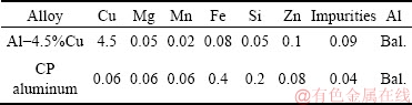
Al-4.5wt.%Cu alloy (as solid insert) and commercially pure (CP) aluminum were used for preparation of an Al/Al-Cu macrocomposite bimetal. Chemical compositions of the alloys, determined by optical emission spectroscopy (OES), are shown in Table 1.
Table 1 Chemical compositions of alloys used (wt.%)
2.2 Fabrication of macrocomposite bimetal
Al/Al-Cu macrocomposite bimetal was prepared by compound squeeze casting process. External pressure was applied by means of a 100 t vertical hydraulic press. A heat treated hot work tool steel (H13) die with inner diameter of about 100 mm and height of about 90 mm was used in the process as schematically shown in Fig. 1(a). The die was coated with a dilute graphite suspension before each test.

Fig. 1 Schematic illustration of compound squeeze casting process
First, based on previous experiences [19-22], an Al-4.5wt.%Cu solid insert (100 mm diameter and (25��1) mm height) was prepared by squeeze casting in the same die at pouring temperature of 750 ��C, die temperature of 250 ��C and 70 MPa external pressure. The insert was then degreased by rinsing with ethanol and distilled water and its top surface was ground with P180 sandpaper to an average surface roughness (Ra) of 0.615 ��m. This was to remove the existing oxide layer on the insert surface and facilitate diffusion bonding of the two components. Nevertheless, due to the rapidity of formation of the undesired oxide layer, this conventional treatment is hardly successful to get rid of surface oxide layer completely. Figure 2 shows a squeeze cast Al-4.5wt.%Cu insert and its surface condition before being placed in the compound casting die.
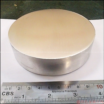
Fig. 2 Squeeze cast Al-4.5wt.%Cu insert and its surface condition before compound casting
The solid insert was placed at the bottom of the die (Fig. 1(b)) and both were preheated to 350 ��C using an electrical heater. Subsequently, 600 g of CP aluminum ingot melted in an electric furnace was poured on top of the solid insert. The pouring temperature and time were 800 ��C and 4 s, respectively. The punch was then lowered and came in contact with the free surface of the liquid aluminum within about 6 s applying a 70 MPa pressure during solidification of the upper part of the bimetal. The pressure was held for 5 min to result in diffusion bonding of the two aluminum components (Fig. 1(c)). At last, the punch was retracted and the solidified Al/Al-Cu macrocomposite bimetal (100 mm in diameter and (45��2) mm in height) was ejected, trimmed and cut into two halves for microstructural and microhardness analyses. Figure 3 demonstrates the two halves of a fabricated and sectioned Al/Al-Cu bimetal part and schematically illustrates the interface region as well as the positions where the metallographic specimen and microhardness measurements were taken. Distances of the closest and furthest microhardness measurement points from the interface are shown in the figure for each half. The horizontal distance between the microhardness measurement points, i.e. 50 mm, is also shown.
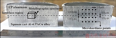
Fig. 3 Fabricated compound casting cut into two halves for microstructural and microhardness analyses
2.3 Characterization of microstructure and microhardness
Microstructural characterizations were carried out according to standard metallographic procedures [23]. Optical microscopy (OM, Nikon EPIPHOT300), scanning electron microscopy (SEM, Seron AIS2300C) and energy dispersive spectroscopy (EDS) were used to assess microstructures of the insert alloy and the interface region of the bimetal. The average grain size of the materials was determined using the Jeffries planimetric and the linear intercept test procedures according to ASTM E112-13 standard [24].
Non-equilibrium temperature-solid fraction relationship of Al-4.5wt.%Cu alloy was estimated using Thermo-Calc software version 4-0-1-5. Non-equilibrium cooling rate during solidification of the insert alloy was predicted by Eq. (1) suggested by SALAS et al [25] for Al-(3.9-4.5)wt.%Cu alloys, where SDAS and C.R. are secondary dendrite arm spacing (��m) and cooling rate (��C/s) of the alloy, respectively.
SDAS=60C.R.-0.33 (1)
Average value of SDAS of the insert was measured by linear intercept method. ImageJ software was used for image analysis of the microstructures. Microhardness of the fabricated bimetal was also measured across the interface region with a Koopa MH3 hardness tester using a Vickers indenter at a load of 0.05 kg and a dwell time of 10 s. The spacing between the indentation marks was about 50 ��m and the average of five measurements taken at any given distance from the interface was reported as the microhardness value at that distance (Fig. 3). Variation ranges of the measurements are also given by error bars in the subsequent figures.
2.4 Simulation of fabrication process
To gain a better understanding of the interfacial phenomena during fabrication process and their effects on the interface microstructure, heat transfer, solidification and distribution of thermal and mechanical stresses along the interface region of the bimetal, the process was simulated using ProCAST 2016 and ANSYS R17.0 softwares.
Heat transfer and solidification sequence of the bimetal were simulated using ProCAST software in two different conditions, i.e. with and without considering an interfacial equivalent oxide layer. For this purpose, a fine optimized 200 ��m planimetric mesh was used for the interface region of the bimetal. Mesh sensitivity analysis showed that 200 ��m was the first value at which simulation results started to converge. As shown in Fig. 4, the die, bimetal component and the interface region were volumetrically meshed. So, the number of two dimensional (triangular type) and three dimensional (tetrahedral type) meshes used for modeling were 189682 and 5658284, respectively.
CP aluminum melt (800 ��C) was poured on the top surface of the solid insert (with or without an equivalent surface oxide layer) inside the die (both preheated to 350 ��C) at a flow rate (inlet) of 113.5 g/s within 4 s.
Table 2 presents the thermophysical properties of the bimetal and mold materials used in the simulations. Variations of temperature and solid fraction with time at 4 selected points in the bimetal (Fig. 5) were then simulated. Points 1 to 3 were taken from surface to depth of the Al-4.5wt.%Cu insert alloy. Point 4 was selected at the center of the hot spot of CP aluminum part where the solidification time is the longest.
Based on the results of NISHIDA and MATSUBARA [26] and the structural results which will be presented in section 3.2, the interfacial heat transfer coefficients were determined for simulation of heat flow across the CP aluminum and the die wall, the CP aluminum and air/punch as well as the CP aluminum and the solid insert alloy. Figure 6 and Table 3 show the boundary conditions and the interfacial heat transfer coefficients used in the simulations. It is necessary to mention that interfacial heat transfer coefficients of the die/air and the die wall/solid insert alloy are independent of external pressure and are taken equal to 10 and 1000 W/(m2��K), respectively [27]. Under the applied external pressure, the resistance to heat transfer between CP aluminum and the solid insert was negligible along the interface. Therefore, heat transfer coefficient should be considered sufficiently higher than other proposed values in Table 3. Due to lack of a precise value in the literature, 1.0��106 W/(m2��K) was used as the heat transfer coefficient value at the interfacial zone of the bimetal proposed in this study.
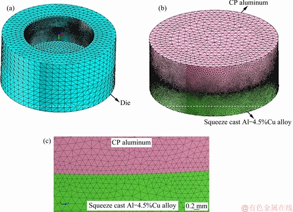
Fig. 4 Finite element mesh of die (a), bimetal component (b) and interface region (c)
Table 2 Thermophysical properties of bimetal and mold materials used for simulation [27]

ANSYS software was used to evaluate the total and equivalent stresses (von Mises stresses) generated along the interface region of the bimetal component. For this purpose, a 2D longitudinal element with dimensions of 100 mm �� 1 mm was selected from the middle of the bimetal. This element has two various components containing a solid aluminum alloy at preheating temperature of 350 ��C and a molten pure aluminum at 800 ��C. Then, an optimized 1 mm planimetric mesh was applied to both of them (Fig. 7). The number of two dimensional (triangular type) meshes was 42482. A steady-state compressive load of 7000 N corresponding to the external pressure used for fabrication of the bimetal was applied on the top surface of the element. A high magnification view of the element as well as the location of the 7000 N compressive load are shown in Fig. 8.
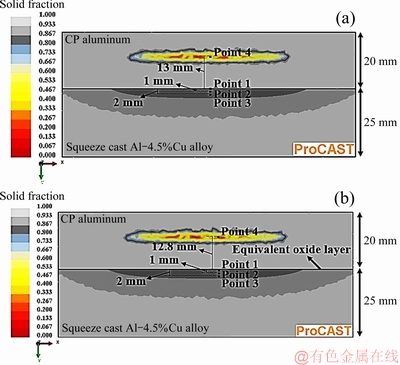
Fig. 5 Four selected points where variations of temperature and solid fraction with time were computed without (a) and with (b) considering interfacial equivalent surface oxide layer
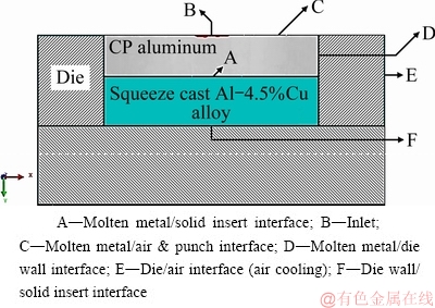
Fig. 6 Interfaces of bimetal fabrication set-up used for simulation
Table 3 Interfacial heat transfer coefficients before and after applying pressure [26,27]
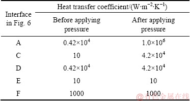
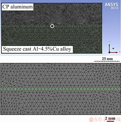
Fig. 7 Finite element mesh of element selected from middle of bimetal component
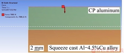
Fig. 8 Location of 7000 N steady-state compressive load applied on upper surface of longitudinal element
3 Results and discussion
3.1 Simulation of solidification and heat transfer
During the compound squeeze casting process, molten CP aluminum was poured on a preheated Al-4.5wt.%Cu insert followed by applying 70 MPa external pressure. The insert surface was ground just before the process to remove the existing oxide layer on its surface and facilitate bonding of the two components.
It is known, however, that oxidation of aluminum is very fast and as soon as a fresh aluminum surface is subjected to air, an amorphous aluminum oxide layer, ��-Al2O3, with a final average thickness of 2-4 nm starts to form on its surface. This leads to the distinguished oxidation resistance of aluminum and its alloys [28].
Besides, being thermodynamically stable, the oxide layer formed is highly adherent to the aluminum substrate. Pilling and Bedworth ratio (PBR) of Al2O3/Al system is reported to be about 1.28 [29]. PBR is the molar volume ratio of a metal oxide to its corresponding metallic substrate and is used to predict the protectiveness of a surface oxide layer from its base metal during corrosion and oxidation processes [29,30]. An oxide layer would be unprotective if the metal has a PBR of much less than unity or much over 2. In the former, the oxide layer becomes porous, and in the latter, it would crack during formation. On the other hand, metals with PBR ratios of about unity tend to form an effective surface barrier layer against further oxidation of the base metal [31].
PBR ratio of 1.28 for Al2O3/Al system is known to provide satisfactory adherence of a continuous oxide layer to the base metal which is relatively free from compressive stresses stemming from molar volume difference between the metal and its surface oxide layer [28].
Therefore, despite the effort to remove the existing oxide layer on the insert surface by grinding, reformation of a thin oxide layer on the insert surface seems inevitable during manufacturing process of aluminum- aluminum macrocomposite bimetals in this work.
Nevertheless, in the preliminary simulation attempts in this research, the effects of this oxide layer were neglected due to the following reasons. Thickness of the natural surface oxide layer has been reported to be only about 4 nm [28,32]. Furthermore, during the compound squeeze casting process, this layer experiences large thermal and mechanical stresses caused by the thermal shock of pouring and the applied pressure. As a result, it may be assumed that these effects would result in breaking and discontinuity of the thin oxide layer formed on the surface diminishing its effect on heat transfer along the interface.

Fig. 9 ProCAST simulation results of ten different time steps after start of pouring molten CP aluminum in die for fabrication of bimetal without interfacial oxide layer
Assuming no oxide layer at the interface, mold filling and the change of solid fraction in the CP aluminum and the insert were simulated. Ten different progressive steps of the simulation are shown in Fig. 9. As it is evident from Figs. 9(a-c), during the filling period (first 4 seconds) while molten CP aluminum is continuously poured into the die, no solidification takes place. It seems that super heat of the molten metal is large enough to keep the melt temperature above 660 ��C during this period of time preventing any solidification. Consequently, only heat transfer through the die and the insert has occurred.
Using Thermo-Calc software, the temperature-solid fraction curve of Al-4.5wt.%Cu alloy in non-equilibrium condition was approximated as shown in Fig. 10 and the non-equilibrium solidus and liquidus temperatures of the alloy were found to be about 547 and 648 ��C, respectively. During the first 4 seconds of fabrication process, no change in the solid fraction of the lower part, i.e. the Al-4.5wt.%Cu insert, is observed. In other words, during this period although the insert is being heated up by the heat transfer from the poured molten CP aluminum, its interface temperature has not reached the solidus temperature of Al-4.5wt.%Cu alloy (547 ��C).

Fig. 10 Thermo-Calc prediction of non-equilibrium temperature-solid fraction curve of Al-4.5wt.%Cu alloy at 14 ��C/s cooling rate
When pouring is stopped, a directional solidification front sets out towards the center of the CP aluminum component due to the directional heat transfer from the die walls and the insert surface. Figure 9(d) shows the solidification initiation in 10 s after the start of pouring and just when the punch is coming in contact with the free surface of the melt. At this time, the solid fraction of the Al-4.5wt.%Cu insert has not changed yet.
Upon contact of the punch with free surface of the molten metal, a new solidification front starts from the top surface of the insert (Fig. 9(e)). Furthermore, with applying 70 MPa pressure at the 10th second, the interfacial heat transfer coefficient at all the interfaces is assumed to increase abruptly (Table 3). This results in accelerated solidification towards the hot spot of the CP aluminum component. Solidification of this part finishes in about 7 s, i.e. 17 s from the start of the process (Figs. 9(d-i). Figures 9(e-i) also predict that while the CP aluminum solidifies, surface of the solid insert starts to melt due to release of the latent heat of solidification of the CP aluminum part. Simultaneously solid fraction of the insert decreases to a minimum value. On the other hand, a mushy zone is formed from the interface to a certain depth of the solid insert. Finally, solidification of melted zone of the Al-4.5wt.%Cu insert is completed after 25 s from the start of the process (Fig. 9(j)).
Figure 11 demonstrates the simulated temperature- time and solid fraction-time curves of the four selected points shown in Fig. 5(a). This figure predicts that during the first 10 s of the process, temperature at point 1 (at the interface) is increased from 350 to 405 ��C with an average heating rate of about 5.5 ��C/s. Simulation results showed no change in the solid fraction of the insert during this time period. By applying the external pressure at the 10th second, the interfacial heat transfer coefficient increases. At the same time, the latent heat of solidification of the CP aluminum melt is released. Consequently, as shown in Fig. 11, the heating rate of the solid insert increases rapidly due to these two effects. So, after a short period of time, temperature and liquid fraction at point 1 are increased to a maximum value of about 625 ��C and 0.3, respectively. The maximum temperature and liquid fraction at points 2 and 3 reach about 598 ��C and 0.17 and 588 ��C and 0.15, respectively.

Fig. 11 Simulated curves of temperature-time (a) and solid fraction-time (b) for four selected points shown in Fig. 5(a)
Temperature-time and solid fraction-time curves of the hottest zone of the CP aluminum part, i.e. point 4, show that temperature is reduced down to 720 ��C at an average cooling rate of 8 ��C/s prior to the application of pressure. The solid fraction-time curve at point 4 indicates solidification time of 3.1 s, i.e. from 14 to 17.1 s of the process.
In summary, ProCAST simulation results showed that when no interfacial oxide layer was assumed to exist on the top surface of the solid insert, the maximum value of liquid fraction on the top surface of the insert (the bimetal components interface) reached 0.3.
3.2 Microstructural investigation of insert
To check the validity of the simulation results, microstructure of the Al-4.5wt.%Cu insert was characterized and the probable changes in the microstructure during the fabrication process were studied.
As squeeze cast macrostructure and microstructure of the Al-4.5wt.%Cu insert are shown in Fig. 12. It consists of relatively fine uniform equiaxed dendritic grains of proeutectic ��(Al) phase surrounded by the low melting point eutectic phases of ��(Al) and Al2Cu at the grain boundaries. According to the image analyses, the average number of grains per square millimeter, grain diameter and secondary dendrite arm spacing (SDAS) in the microstructure of as squeeze cast Al-4.5wt.%Cu insert are about 16, 208 ��m and 25 ��m, respectively. Using the latter and Eq. (1), the average cooling rate during squeeze casting of the insert alloy was estimated to be about 14 ��C/s. It must be noted that the temperature-solid fraction curve of Al-4.5wt.%Cu alloy presented in Fig. 10 was generated by Thermo-Calc software at this cooling rate.
According to Fig. 10, the microstructure of the alloy solidified at such cooling rate would consist of 89% dendritic grains of proeutectic ��(Al) phase and 11% eutectic phases of ��(Al) and Al2Cu at the grain boundaries. On the other hand, the ProCAST simulation results predicted formation of 30% liquid on the top surface of the insert during the compound squeeze casting process. Consequently, one would expect complete melting of the intergranular eutectic phases and partial melting of the primary proeutectic phases at the bimetal interface. In other words, about 37% (11/30) of the formed liquid on the top surface of the insert is predicted to be due to melting of all the eutectic intergranular phases and about 63% (19/30) of it due to melting parts of the proeutectic ��(Al) dendrites. About 21% (19/89) of the proeutectic ��(Al) dendrites is melted in this process. Due to higher concentration of the alloying elements at the roots of the secondary dendrite arms resulting in lower melting point of the solid in these areas, one would expect separation of some of the secondary dendrite arms from their parent primary arms and formation of new grains upon cooling of the interface. Under such circumstances, some macro and microstructural changes on the insert top surface after compound squeeze casting seem inevitable.
Macrostructure of the fabricated bimetal and microstructures of the two marked zones are presented in Figs. 13(a) and 13(b), respectively. Figure 13(a) shows a typical solidification macrostructure for the CP aluminum part consisting of fine equiaxed chill zone grains and long columnar grains. Growth of two solidification fronts arising from the interface and the punch is evident in this figure. Fine equiaxed dendritic microstructure of the Al-4.5wt.%Cu insert is shown in Fig. 13(b). No significant microstructural changes are evident from comparison of this figure with Fig. 12(b). Furthermore, according to the image analyses results, the average number of grains per square millimeter of zones 1 and 2 of the insert is about 18 and 15, respectively. The average grain diameters of zones 1 and 2 of the insert are about 192 and 204 ��m, respectively. Comparing these values with those of the squeeze cast insert before compound squeeze casting also confirms that no significant change has taken place in the microstructure of the top surface of the insert. The small differences in the measurements are within the normal microstructural variations. This is in disagreement with the simulation predictions of ProCAST software as explained in previous section.

Fig. 12 Macrostructure (a) and microstructure (b) of squeeze cast Al-4.5wt.%Cu alloy

Fig. 13 Macrostructure of fabricated bimetal and locations of two selected zones of insert (a) and microstructures of two specified zones (b, c)
3.3 Microscopic and microhardness analyses of interface
Figure 14 shows optical micrographs of the interface region of the fabricated bimetal. A continuous boundary at the interface between the two parts of the bimetal is evident in these microstructures. It seems that application of 70 MPa pressure has resulted in an intimate contact between the two components and hindered the formation of local defects and discontinuities along the interface. The transition zone, where the dendritic structure of the squeeze cast Al-4.5wt.%Cu insert is changed to the microstructure of CP aluminum, is very narrow, if any, for the bimetal.
SEM micrograph and EDS analysis of copper content along the line crossing the interface of the bimetal are shown in Figs. 15(a) and (b), respectively. A sharp increase in copper content at the interface of the two components is clearly seen in Fig. 15(b). A very low copper content in the CP aluminum and a high copper content in the Al-4.5wt.%Cu insert alloy are characteristics of this concentration profile.
Variations of microhardness along the interface are presented in Fig. 15(c). Microhardness measurement positions are shown in Fig. 3. While the microhardness profile is reasonably flat in both the CP aluminum and the insert parts, a steep increase in the microhardness at the interface is evident. Microhardness values in the CP aluminum part and the squeeze cast Al-4.5wt.%Cu insert are in the ranges of HV 24-29 and HV 50-65, respectively. These changes match those of the copper content across the interface.
EDS and microhardness analyses, suggest no or limited diffusion or micromixing of copper in the interfacial region of the bimetal. From the microstructural analyses, it seems that no (or very limited) melting and resolidification of the insert top surface have happened during the fabrication process either. These are in disagreement with the simulation results that predicted formation of about 30% liquid on the top surface of the Al-4.5wt.%Cu insert. It seems that there is a missing parameter in the simulation conditions resulting in disagreement of the simulation and experimental results. The missing parameter must affect the heat transfer across the bimetal interface and hamper the diffusion of the released specific and solidification latent heat from the CP aluminum part to the insert top surface.
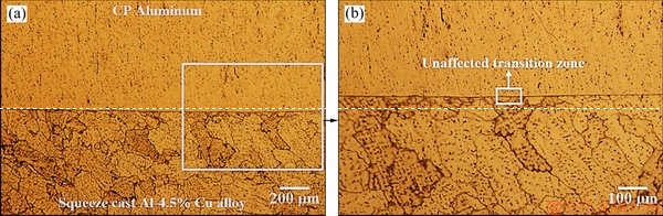
Fig. 14 Optical micrographs of interface region of fabricated bimetal
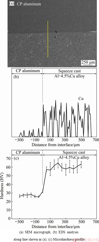
Fig. 15 Microstructural and microhardness analyses across interface of bimetal
It may be postulated that despite the initial mechanical abrasion of the insert top surface, a continuous and stable high melting point oxide layer still persists on the insert surface. This oxide layer could impede the heat transfer across the interface. It also obstructs the direct contact between the insert and the molten CP aluminum and, as a result, would allow for no mixing or alloying across the interface. This problem has been dealt with by other researchers who have resorted to extensive chemical treatments on the top surface of the solid inserts before the compound casting process [8,11-18]. In this work, no chemical treatment was used and therefore persistence of an oxide layer on the insert surface is very likely. The effect of such layer on solidification and heat transfer of the bimetal is considered in the next section.
3.4 Simulation of solidification and heat transfer in the presence of equivalent oxide layer
In the ProCAST environment, the oxide layer between the two parts of the bimetal can be defined as a thermal barrier at the interface and the corresponding portion of thermal resistance (Rth) induced by the oxide layer can be calculated by Eq. (2), where Radherence is adherence resistance between the oxide layer and its substrate, K is the conductivity and L is the thickness of the layer [27].
Rth=Radherence+L/K (2)
Assuming a complete contact between the oxide layer and the insert surface under the applied pressure, Radherence can be assumed negligible. Actual values of conductivity (K) and thickness (L) of the aluminum oxide layer are about 30 W/(m��K) [33] and 4 nm [32], respectively. Consequently, from Eq. (2), the thermal resistance between the two bimetal components is about 1.33��10-10 m2��K/W.
On the other hand, the minimum thickness which could be defined in ProCAST software for the thermal barrier layer is 1 ��m. Inevitably, L was taken as 1 ��m in this simulation, which is two hundred and fifty times that of the reported L value. In order to induce a realistic thermal resistance in the simulation (Rth= 1.33��10-10 m2��K/W, conductivity of the equivalent oxide layer (K) was taken as 75��102 W/(m��K) which is also two hundred and fifty times that of the practical value.
Figure 16 shows ten different progressive simulation steps of the bimetal fabrication process assuming an oxide layer between the two parts of the bimetal. It shows that sequence of solidification and heat transfer are almost identical to that when no interfacial oxide layer was considered (Fig. 9). Figure 17 shows temperature-time and solid fraction-time relationship of the four selected points shown in Fig. 5(b) in the presence of the equivalent oxide layer. It is evident that the maximum temperature and liquid fraction reached at point 1 (located just below the oxide layer) are about 593 ��C and 0.15, respectively. Clearly, despite the relatively low amount of the interfacial thermal resistance between the two parts of the bimetal (1.33��10-10 m2��K/W), the maximum liquid fraction on the surface decreased by 50% (from 0.3 to 0.15), compared to the condition where the effect of the oxide layer was ignored.
As shown in Fig. 17, temperature, solid fraction and solidification time of the hottest zone of the CP aluminum part, i.e. point 4, are almost the same as those when no interfacial oxide layer was assumed between the two components. Only the position of point 4 was lowered by 0.2 mm when the effects of the oxide layer was considered (Fig. 5(b)) due to decrease in heat flow across the interface region.
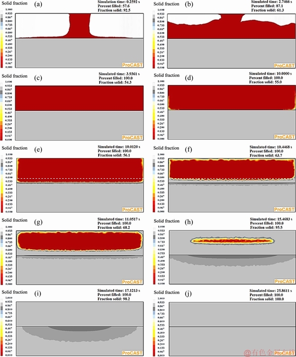
Fig. 16 ProCAST simulation results of ten different time steps after start of pouring molten CP aluminum in die for fabrication of bimetal in the presence of interfacial equivalent oxide layer
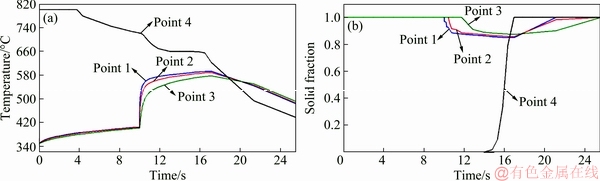
Fig. 17 Simulated curves of temperature-time (a) and solid fraction-time (b) for four selected points in the presence of equivalent oxide layer on top surface of insert
These simulation results are in reasonable agreement with the microstructural observations reported in Section 3.2. According to Thermo-Calc predictions, there must be about 11% low melting point eutectic constituents available at the grain boundaries of the squeeze cast insert (Fig. 10). Therefore, only 4% of the mentioned 15% liquid needs to be provided by melting of the proeutectic solid phase. This constitutes only 4.5% (4/89) of the proeutectic ��(Al) dendrites. As a result, no significant change in the microstructure would be expected as confirmed by microstructural examinations.
Agreement of the simulation and experimental results when the effects of the oxide layer on heat transfer are considered, raises the question of how such thin oxide layer would resist the imposed thermal and mechanical stress during the fabrication process. Stability of such oxide layer depends on magnitude and distribution of the applied interfacial stresses. Therefore, thermal and mechanical interfacial stresses induced in the oxide layer were simulated using ANSYS software and are presented in the next section.
3.5 Simulation of stress at interface
During the compound squeeze casting process, thermal and mechanical stresses are generated at the interface of the two parts of the fabricated bimetal. The stresses may be induced by: (1) pouring the hot (800 ��C) molten CP aluminum on the cooler (350 ��C) surface of the solid insert; (2) applying an external pressure (70 MPa) on the molten component, and (3) high temperature transformations in the oxide layer during the fabrication process.
Pouring the molten metal on the insert increases its temperature and, accordingly, the thickness of the amorphous oxide layer. Previous researches have shown that growth of the amorphous oxide layer can be accompanied by its crystallization to phases such as ��-Al2O3, ��-Al2O3, ��-Al2O3 and ��-Al2O3, which have specific volumes lower than that of the initial amorphous oxide layer [34]. These transformations may cause some interfacial stresses on the oxide layer. However, each transformation needs an incubation time at high temperature which does not seem to be provided in the manufacturing process of the bimetal. Therefore, the effects of crystallization of the oxide layer during the fabrication process was ignored in this simulation.
The results of ANSYS simulation of the magnitude and distribution of the equivalent von Mises stresses at the interface of the bimetal are shown in Fig. 18. Value of the total equivalent induced stress between the components is shown in the magnified images in the right hand side and bottom of the figure. It should be noted that Y and X axes represent directions of normal and shear stresses applied on the interfacial oxide layer. Figure 18 shows a uniformly distributed total equivalent von Mises normal stress of 406 MPa along the interface of the bimetal. Compressive strength of high purity Al2O3 is 2660 MPa [33], which is significantly higher than the generated stress at the interface. There is no stress gradient in the oxide layer either. So based on the results of this simulation, the surface oxide layer is unlikely to be damaged by these thermal and mechanical stresses during the fabrication process. In other words, the oxide layer is mechanically stable and remains adhered to the substrate surface during the process. Therefore, it may act as a stable high melting point thermal barrier and decrease the thermal effects of CP aluminum component on heat and mass transfer across the bimetal interface, as well as the microstructure of the insert. This justifies the assumption made in Section 3.4 for ProCAST simulation of solidification and heat transfer and is in good agreement with the experimental results.
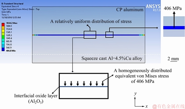
Fig. 18 ANSYS simulation of magnitude and distribution of stresses generated at interface of bimetal during compound squeeze casting
It may be envisaged that the presence of such continuous oxide layer between the two parts of the bimetal would obstruct good bonding between the parts and result in inferior mechanical properties. Review of the previous works indicates that even extensive chemical treatment of the surfaces before the process does not always result in a good bonding between the two parts [8,11-18]. This is due to very high propensity of aluminum for oxide formation. The authors are examining an alternative mechanical treatment of the insert to overcome this problem. The results of this study will be published soon.
4 Conclusions
(1) Despite the initial simulation results, no noticeable melting or change in the structure of the top surface of the solid Al-4.5wt.%Cu insert occurred. Also no obvious transition zone was formed between the two parts of the fabricated bimetal nor any micromixing and diffusion of copper atoms across the interface of the bimetal were detected.
(2) A good agreement between the simulation results and the microscopic observations was achieved when an equivalent oxide layer at the interface was defined and its effect on heat transfer between the two parts of the bimetal was taken into account.
(3) The predicted maximum liquid fraction formed on the insert top surface at this condition was 0.15. This would result in negligible melting of the proeutectic ��(Al) dendrites and, therefore, no significant change in the structure of the insert.
(4) Simulation of the generated stresses at the interface of the bimetal showed a uniformly distributed stress along the interface which was significantly lower than the compressive strength of the oxide layer. This would result in good stability and adherence of the oxide layer to the insert surface during the compound squeeze casting process.
(5) Before any good bonding between the two parts of the bimetal can be realized, the effects of this continuous stable oxide layer must be overcome.
Acknowledgments
The authors would like to thank the financial support from Iran National Science Foundation (INSF) under grant number 95822903.
References
[1] Avner S H. Introduction to physical metallurgy [M]. 2nd ed. USA: McGraw-Hill, 1988.
[2] Tayal R K, Singh V, Kumar S, Garg R. Compound casting- a literature review [C]//Proc trends and advances in mechanical engineering. Faridabad, India: YMCA University of Science and Technology, 2012: 501-510.
[3] Hirsch J R, Al-Samman T. Superior light metals by texture engineering: Optimized aluminum and magnesium alloys for automotive applications [J]. Acta Materialia, 2013, 61: 818-843.
[4] Bitsche R D. Design and computational analysis of compound castings and other multi-material structures [D]. Denmark: Vienna University of Technology, 2009.
[5] Anifantis N K, Georgantzinos S K, Giannopoulos G I, Kakavas P A. Elastomer macrocomposites [J]. Advanced Structured Materials, 2013, 12: 11-68.
[6] Yan G Y, Mao F, Chen F, Wu W, Cao Z Q, Wang T M, Li T J. Characteristics evolution of 6009/7050 bimetal slab prepared by direct-chill casting process [J]. Transactions of Nonferrous Metals Society of China, 2016, 26: 895-904.
[7] Bykov A A. Bimetal production and applications [J]. Steel in Translation, 2011, 41: 778-786.
[8] Liu T, Wang Q D, Liu P, Sun J W, Yin X L, Wang Q G. Microstructure and mechanical properties of overcast aluminum joints [J]. Transactions of Nonferrous Metals Society of China, 2015, 25: 1064-1072.
[9] LI Y Y, ZHENG X P, ZHANG W W, LUO Z Q. Effect of deformation temperature on microstructures and properties of 7075/6009 alloy [J]. Transactions of Nonferrous Metals Society of China, 2009, 19(5): 1037-1043.
[10] Klassen A, Rubner M, Ilg J, Rupitsch S J, Lerch R, Singer R F, Korner C. Influence of the fabrication process on the functionality of piezoceramic patch transducers embedded in aluminum die castings [J]. Smart Materials and Structures, 2012, 21: 1-11.
[11] Liu G, Wang Q, Liu T, Ye B, Jiang H, Ding W. Effect of T6 heat treatment of microstructure and mechanical property of 6101/A356 bimetal fabricated by squeeze casting [J]. Materials Science and Engineering: A, 2017, 696: 208-215.
[12] Feng J, Ye B, Zuo L, Wang Q, Wang Q, Jiang H, Ding W. Bonding of aluminum alloys in compound casting [J]. Metallurgical and Materials Transactions A, 2017, 48: 4632-4644.
[13] Papis K J M, Loeffler J F, Uggowitzer P J. Light metal compound casting [J]. Science China Technological Sciences, 2009, 52: 46-51.
[14] Papis K J M, Hallstedt B, Loffler J F, Uggowitzer P J. Interface formation in aluminum-aluminum compound casting [J]. Acta Materialia, 2008, 56: 3036-3043.
[15] Rubner M, Gunzl M, Korner C, Singer R F. Aluminum-aluminum compound fabrication by high pressure die casting [J]. Materials Science and Engineering A, 2011, 528: 7024-7029.
[16] Koerner C, Schwankl M, Himmler D. Aluminum- aluminum compound castings by electroless deposited zinc layers [J]. Journal of Materials Processing Technology, 2014, 214: 1094-1101.
[17] Liu T, Wang Q, Sui Y, Wang Q, Ding W. An investigation in to aluminum-aluminum bimetal fabrication by squeeze casting [J]. Materials & Design, 2015, 68: 8-17.
[18] Liu T, Wang Q, Sui Y, Wang Q. Microstructure and mechanical properties of overcast 6101-6101 wrought Al alloy joint by squeeze casting [J]. Journal of Materials Science and Technology, 2016, 32: 298-304.
[19] Maleki A, Shafyei A, Niroumand B. Effects of squeeze casting parameters on the microstructure of LM13 alloy [J]. Journal of Materials Processing Technology, 2009, 209: 3790-3797.
[20] Maleki A, Niroumand B, Shafyei A. Effects of squeeze casting parameters on density, macrostructure and hardness of LM13 alloy [J]. Materials Science and Engineering A, 2006, 428: 135-140.
[21] Khodaverdizadeh H, Niroumand B. Effects of applied pressure on microstructure and mechanical properties of squeeze cast ductile iron [J]. Materials & Design, 2011, 32: 4747-4755.
[22] Shayan M, Niroumand B. Synthesis of A356-MWCNT nanocomposites through a novel two stage casting process [J]. Materials Science and Engineering A, 2013, 582: 262-269.
[23] ASTM Standard-E407. Standard practice for microetching metals and alloys [S].
[24] ASTM Standard-E112. Standard test methods for determining average grain size [S].
[25] Salas G F, Noguez N E, Ramirez J G, Robert T. Application of secondary dendrite arm spacing-cooling rate equation for cast alloys [J]. AFS Transactions, 2000, 108: 593-597.
[26] Nishida Y, Matsubara H. Effect of pressure on heat transfer at the metal-mold casting interface [J]. The British Foundryman, 1976, 69: 274-278.
[27] ESI Group. ProCAST user��s manual [M]. The Virtual Try Out Space Company, 2016.
[28] GHALI E. Corrosion resistance of aluminum and magnesium alloys: Understanding, performance, and testing [M]. USA: Wiley, 2010.
[29] XU C, WEI G. Pilling-Bedworth ratio for oxidation of alloys [J]. Material Research Innovations, 2000, 3: 231-235.
[30] PILLING N B, BEDWORTH R E. The oxidation of metals at high temperatures [J]. Journal of the Institute of Metals, 1923, 29: 529-591.
[31] GILMORE C M. Materials science and engineering properties [M]. USA: Cengage Learning, 2014.
[32] Campbell T, Kalia R K, Nakano A, Vashishta P. Dynamics of oxidation of aluminum nanoclusters using variable charge molecular-dynamics simulations on parallel computers [J]. Physical Review Letters, 1999, 82: 4866-4869.
[33] ASTM Standard-D2442. Standard specification for Alumina ceramics for electrical and electronic applications [S].
[34] Trunov M A, Schoenitz M, Dreizin E L. Effect of polymorphic phase transformations in alumina layer on ignition of aluminum particles [J]. Combustion Theory and Modeling, 2006, 10: 603-623.
���ϼ�ѹ����Al/Al-Cu˫������۸��ϲ����н�������õ�ģ����ʵ����֤
Mohammad Hossein BABAEE1, Behzad NIROUMAND1, Ali MALEKI2, Meysam LASHANI ZAND1
1. Department of Materials Engineering, Isfahan University of Technology, Isfahan 84156-83111, Iran;
2. Department of Mechanical Engineering, Isfahan University of Technology, Isfahan 84156-83111, Iran
ժ Ҫ���о����ϼ�ѹ�����˫������۸��ϲ����������֮����ȡ���ѧ����á����ȣ����ø��ϼ�ѹ���칤���Ʊ�Al/Al-4.5wt.%Cu˫������۸��ϲ��ϡ�Ȼ������Thermo-Calc��ProCAST��ANSYS��������˫�����е��ȴ��ݡ����̺��ؽ�����������Ӧ���ֲ����з��������о�˫�����������Ľṹ��ͭ�ֲ�����Ӳ�ȱ仯�����������Al-4.5wt.%Cu�Ľṹû�����Ա仯��ͭ�ڽ��洦�����Ե���Ϻ���ɢ������������ϵĵ�Ч�����㣬��������Դ��ȵ�Ӱ��ʱ��ģ������ʵ�����ǺϽϺá�����������ʹ��Ƕ��������γɵľֲ�Һ������½�50%���Բ�����Ӧ������ģ�⣬�������������Ӧ���ֲ����ȣ�����Ŀ�ѹǿ�����Ե���������Ŀ�ѹǿ�ȣ����Ʊ������о������õ��ȶ��ԡ���ˣ�������Ϊ�����������������㲻�������ϵ����ã�����ֹ�����Ͻ������ֱ�ӽӴ���
�ؼ��ʣ�Al/Al-Cu ��۸��ϲ��ϣ�˫���������ϼ�ѹ���죻ģ�⣻���棻Ӧ��
(Edited by Xiang-qun LI)
Corresponding author: Behzad NIROUMAND; Tel: +98-31-33915731; Fax: +98-31-33912752; E-mail: behzn@cc.iut.ac.ir
DOI: 10.1016/S1003-6326(19)65004-1
Abstract: The objective of this work was to investigate the thermal and mechanical interactions between the two components of a compound squeeze cast macrocomposite bimetal. First, an Al/Al-4.5wt.%Cu macrocomposite bimetal was fabricated by compound squeeze casting process. Then, heat transfer, solidification and distribution of the generated stresses along the interface region of the bimetal were analyzed using Thermo-Calc, ProCAST and ANSYS softwares, and structure, copper distribution and microhardness changes across the interface of the bimetal were studied. The results showed no noticeable change in the structure of the Al-4.5wt.%Cu insert and no obvious micromixing and diffusion of copper across the interface. Simulation results were in good agreement with the experimental ones only when an equivalent oxide layer at the interface was defined and its effect on heat transfer was considered. This layer caused up to 50% decrease in local liquid fraction formed on the surface of the insert. Simulation of the generated stresses showed a uniformly distributed stress along the interface which was significantly lower than the compressive strength of the oxide layer, resulting in its good stability during the fabrication process. It was postulated that this continuous oxide layer not only acted as a thermal barrier but prevented the direct metal-metal contact along the interface as well.
[1] Avner S H. Introduction to physical metallurgy [M]. 2nd ed. USA: McGraw-Hill, 1988.
[7] Bykov A A. Bimetal production and applications [J]. Steel in Translation, 2011, 41: 778-786.
[23] ASTM Standard-E407. Standard practice for microetching metals and alloys [S].
[24] ASTM Standard-E112. Standard test methods for determining average grain size [S].
[27] ESI Group. ProCAST user��s manual [M]. The Virtual Try Out Space Company, 2016.
[31] GILMORE C M. Materials science and engineering properties [M]. USA: Cengage Learning, 2014.
" target="blank">[34] Trunov M A, Schoenitz M, Dreizin E L. Effect of polymorphic phase transformations in alumina layer on ignition of aluminum particles [J]. Combustion Theory and Modeling, 2006, 10: 603-623.
