
J. Cent. South Univ. (2016) 23: 3153-3159
DOI: 10.1007/s11771-016-3381-9

Parametric analysis of mixed lubrication characteristics in work zone of strip rolling
WU Jian-qing(�⽨��), LIANG Xiao-ping(��Сƽ), PAN Fu-sheng(�˸���)
College of Materials Science and Engineering, Chongqing University, Chongqing 400045, China
 Central South University Press and Springer-Verlag Berlin Heidelberg 2016
Abstract:
A theoretical model for mixed lubrication with more accurate contact length has been developed based on the average volume flow model and asperity flattening model, and the lubricant volume flow rate and outlet speed ratio are determined by integrating differential equations based on rolling parameters. The lubrication characteristics at the roll-strip interface with different surface roughness, rolling speed, reduction and lubricant viscosity are analyzed respectively. Additionally, the average volume flow rates of lubricant under different rolling conditions are calculated and used to explain the change rule of lubrication characteristics. The developed scheme is able to determine the total pressure, lubricant pressure, film thickness and real contact area at any point within the work zone. The prediction and analysis of mixed lubrication characteristics at the interface is meaningful to better control the surface quality and optimize the rolling process.
Key words:
mixed lubrication; rolling; film thickness; real contact area��
1 Introduction
Lubrication technology has been widely used in rolling process to improve the surface quality of metal products and to reduce roll wear. In the work zone (WZ), part of the load is carried by asperity peaks and part by the lubricant in surface valleys in most cases. The flattening of asperity is mainly determined by the normal pressure and friction interacted with roll in the WZ [1-2]. Moreover, the surface quality of strip is also influenced by the roll due to the function of ��running-in�� and ��ploughing�� [3-5], which is related to the lubrication characteristics at the roll-strip interface. Theoretical analysis of the lubrication and friction behaviors for rolling process has been an important method to understand the interfacial conditions in the WZ [6-7]. Based on the researches by WILSON��s research group [8-11], the influence of rolling speed on the interfacial contact conditions has been the main research content. However, the analysis of lubrication characteristics in the rolling deformation zone with different initial surface roughness has never been investigated. For the researches of lubrication characteristics with different rolling parameters such as rolling speed, oil viscosity and rolling reduction [6, 12-13], there are some improvements that can be made: 1) The flow of lubricant is changed for mixed-film lubrication, it would be inaccurate under the assumption of constant flow rate; 2) The outlet speed ratio should be determined based on the rolling parameters.
In this work, a theoretical model for the mixed lubrication in the WZ is developed based on the average volume flow model and asperity flattening model with more accurate contact length, which is related to the roll radius, initial thickness of strip and rolling reduction. And then the effects of initial surface roughness, rolling speed, oil viscosity and rolling reduction on the mixed lubrication characteristics are discussed and analyzed.
2 Theoretical model
Along with the rolling direction, the length of inlet and outlet zone is relatively shorter compared with that of the WZ, which is also the main area where load and heat transfer occur. The geometry of the rolling process to be analyzed is shown in Fig. 1. For the lubrication with O/W emulsions, the process of droplets capture and increase of oil concentration mainly conducts nearby the inlet, resulting in the highly concentrated emulsion in the WZ. Researches [14-15] have indicated that the oil concentration would reach a level close to 1 in most part of the WZ. Based on the above, neat oil and WZ are chosen as the lubricant and the study area respectively in this article. Some assumptions are defined as follows to simplify the solving process.
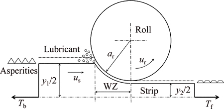
Fig. 1 System of rolling process
1) Rolls are rigid;
2) Strip is rigid perfectly plastic;
3) Thermal effects on viscosity of lubricant are neglected;
4) Width variation of strip is neglected.
2.1 Geometrical model of Asperity
Engineering surfaces usually have directional patterns resulting from different manufacturing processes or because of ��running-in�� [3]. Saw-tooth longitudinal roughness with lay parallel to the rolling direction is regarded as surface topography in the process of rolling. The surface topography of the strip can also be confirmed by the micrographs of the rolled surface [16-17]. The interactions at the interface can be reduced to a simple contact problem between smooth roll and rough strip as shown in Fig. 2. RMS (root-mean-square) surface roughness of the strip can be calculated by
 (1)
(1)
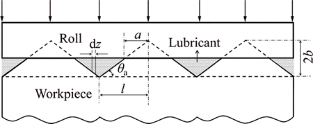
Fig. 2 Surface topography of interface between strip and roll
The following relationships can also be obtained from the geometrical relationship:
 (2)
(2)
 (3)
(3)
A=a/l (4)
where l is the half spacing of asperity; b is the half height of asperity; ht is the average film thickness; a is the half contact length; A is the fractional contact area.
The average film thickness ht can be related to RMS surface roughness and fractional contact area based on Eq. (2)-(4):
 (5)
(5)
2.2 Average flow model
For mixed film lubrication, PATIR and CHENG proposed ��Average Flow Model�� [3, 18] to resolve the problem of lubrication between rough sliding surfaces. The model takes into account the directivity of surface asperity and can explain the flow characteristics of lubricant media more accurately. WU and ZHENG [19] introduced contact factor to reflect the contact rate of the interface of roll and strip. Therefore, the Average Flow Model of PATIR and CHENG [3] and the extended Reynolds equation proposed by YAN and KURODA [20] can be combined to obtain the new ��Average Flow Model�� for mixed lubrication:
 (6)
(6)
where pf is the fluid pressure; us is the surface speed of strip and ur is the rolling speed.
The flow factor f corrector given by CHANG et al [10] for the work zone is adopted:
 (7)
(7)
And the viscosity of lubricant oil �� is given as
 (8)
(8)
where ��0 is the initial viscosity of lubricating oil; �� is the pressure coefficient of viscosity.
In order to compute expediently, the Eq. (6) can be changed to non- dimensional form:
 (9)
(9)
where Pf=pf/��y is the non-dimensional lubricant pressure; Ht=ht/Rq is the non-dimensional average film thickness; C is the constant of integration which has relation to the non-dimensional lubricant volume flow rate by Q*= Q/urRq. The non-dimensional speed F, non-dimensional pressure coefficient G, non-dimensional strip thickness Y and the outlet speed ratio Z are given respectively as follows:
 (10)
(10)
 (11)
(11)
 (12)
(12)
 (13)
(13)
where x1 is the contact length; ��y is the yield stress of strip; R is the rolling reduction which is defined as R=(y1-y2) /y1,  is the outlet speed of strip.
2.3 Rolling stress for mixed lubrication
In the WZ of rolling process, the distribution of rolling stress can be described by Kalman differential equation:
 (14)
(14)
where p is the total pressure, and �� is the friction stress which is the sum of viscous friction of the lubricant and asperity contact friction:
 (15)
(15)
where ��a is the asperity interface friction and ��f is the viscous friction:
 (16)
(16)
 (17)
(17)
where c is the adhesion coefficient; k is the shear strength of strip. Using Eqs. (15)-(17) in Eq. (14), the non- dimensional form of rolling stress distribution with more
accurate contact length (x1= can be expressed as

 (18)
(18)
where P=p/��y is the non-dimensional total pressure; r*=ar/y1 is the non-dimensional roll radius and R*=Rq/y1 is the non-dimensional roughness.
2.4 Fractional contact area
WILSON and SHEU [8] used an upper-bound technique to obtain semi-rational formula about the non-dimensional effective hardness H and the non-dimensional strain rate E:
 (19)
(19)
 (20)
(20)
where pa is the indentation pressure;  is the bulk strain rate; va is the downward speed of the contact surface relative to mean surface and vb is the average upward speed of valleys relative to mean surface. For the purpose of extended calculations, H can be related to A and E by [8]
 (21)
(21)
where
 (22)
(22)
 (23)
(23)
In the WZ, the total pressure consists of the asperity contact pressure and the lubricant pressure:
 (24)
(24)
It can be changed to non-dimensional form:
 (25)
(25)
Based on the asperity flattening theory for longitudinal roughness, CHANG et al [10] developed the frictional contact area model:
 (26)
(26)
where ��a is the asperity slope; l*=l/y1 is the non- dimensional asperity half pitch. The non-dimensional strain rate E can be expressed by
 (27)
(27)
Simultaneous equation composed of Eqs. (9), (18) and (26) is shown as
 (28)
(28)
3 Numerical procedure
To calculate Pf, P and A along with the rolling direction from X=1 to X=0, numerical procedure with a computer programmed Runge-Kutta scheme is used to solve Eq. (28). The boundary conditions are defined as follows. The rolled piece can be regard as rigid at the entrance of rolling process. So, Eq. (21) can be changed to
 (29)
(29)
On the other hand, Pf is usually small and approaches to zero in the condition of low rolling speed, and Eq. (25) can be written as
 (30)
(30)
The rolled piece starts to yield at the entrance, which means P=1. Therefore, the boundary conditions at the entrance can be solved:
 (31)
(31)
Similarly, at the exit of the WZ, Pf will approach to zero and P is approximate to that at the entrance:
Pf=0, p=1 (32)
The frictional contact area will change because of the flattening of asperity. The resolving flow chart is shown in Fig. 3.
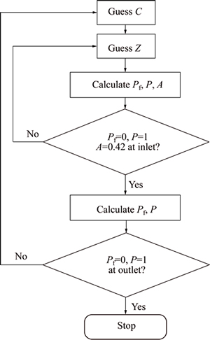
Fig. 3 Flow chart of solving procedures
4 Model verification
To verify the model, the rolling parameters (Table 1) which are similar with those used in Ref. [10] are selected in the following model verification. The result is shown in Fig. 4. It can be seen that the distribution of total pressure, fractional contact area and hydrodynamic pressure calculated by present model agrees well with the results in Ref. [10].
5 Results and discussion
Based on the model, influence of the surface roughness, rolling speed, reduction and lubricant viscosity on the lubrication characteristics such as total pressure, lubricant pressure, film thickness and the real contact area are discussed. An investigation of surface morphology of asperity is made firstly because a constant size of asperity was used in the previous models. The RMS surface roughness is related to the half pitch and slope of asperity as shown in Fig. 2. The relationship between asperity slope and arithmetic average roughness can be obtained by  [21], where Ra=
  The detailed information about the topography of asperity can be calculated based on Ref. [22], and the calculated results are given in Table 2.
Table 1 Rolling parameters used in this work
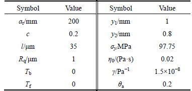
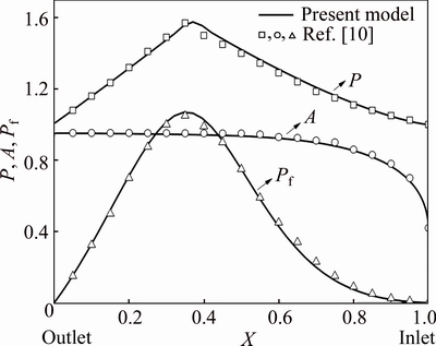
Fig. 4 Distribution of total pressure, fractional contact area and hydrodynamic pressure calculated by present model and Ref. [10]
Table 2 Detailed information about surface roughness
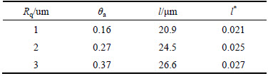
Figure 5 presents the lubrication characteristics in the WZ with different RMS surface roughness. It can be seen that a significant decline of the hydrodynamic pressure occurs when Rq changes from 1 um to 2 um (Fig. 5(a)), indicating that the asperity shares the main pressure when the RMS surface roughness exceeds 2 um. The strip surface with larger valleys is useful to save more lubricant, which can also be observed from the change of volume flow rate of lubricant as shown in Fig. 9. The real contact area decreases with the increasing roughness (Fig. 5(b)), resulting from the change of asperity slope. Due to the larger surface valley, the average film thickness gets higher as shown in Fig. 5(c).
The lubrication characteristics in the WZ under different rolling speed are shown in Fig. 6. The relevant parameter of asperity size is selected from Table 2 in the following calculations. It can be seen that there is no obvious change for the total pressure with different rolling speed (Fig. 6(a)). The higher the rolling speed, the more lubricant is brought into the interface, leading to the smaller real contact area and the higher film thickness (Figs. 6(b) and (c)). Another interesting finding is that the hydrodynamic pressure increases with the increase of rolling speed mainly within the area from inlet to neutral point. The reason for this might be that the process of asperity flattening mainly occurs in the area nearby the inlet.
Figure 7(a) shows the variation of total pressure and hydrodynamic pressure in the WZ with different rolling reduction. Both the pressures increase with the increase of rolling reduction. The real contact area is also influenced by the rolling reduction as well as the film thickness, as shown in Figs. 7(b) and (c).
The viscosity of rolling oil is also an important factor in the choice of lubricant. The higher viscosity contributes to higher hydrodynamic pressure as shown in Fig. 8(a). The lubricant with low viscosity is relatively easy to flow through the surface valleys, resulting in the higher real contact area and the thinner film thickness (Figs. 8(b) and (c)).
Figure 9 presents the average volume flow rate of lubricant in different rolling conditions, i.e., surface roughness, rolling speed, reduction and oil viscosity. It can be observed that the volume flow rate of lubricant increases with the increase of surface roughness, rolling speed and lubricant viscosity, and decreases with the increase of rolling reduction. The variation of volume flow rate agrees well with the change of interfacial lubrication characteristics discussed above.
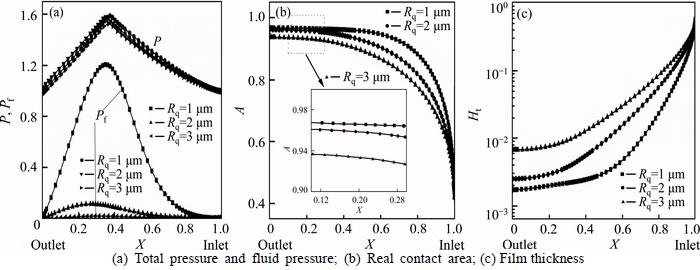
Fig. 5 Lubrication characteristics in WZ with different roughness:
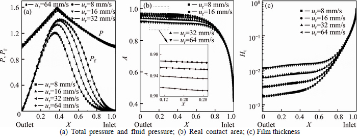
Fig. 6 Lubrication characteristics in WZ with different rolling speed:
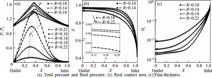
Fig. 7 Lubrication characteristics in WZ with different reduction:
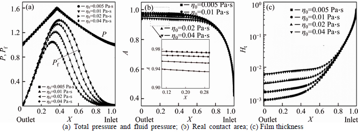
Fig. 8 Lubrication characteristics in WZ with different lubricant viscosity:
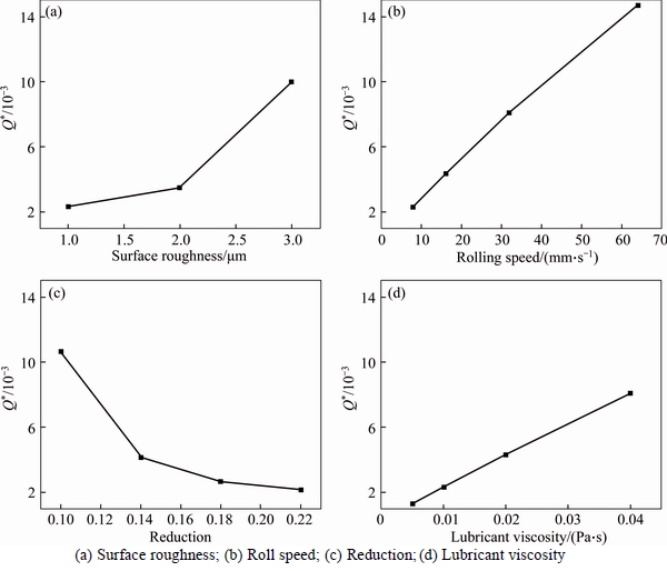
Fig. 9 Average volume flow rate of lubricant under different rolling conditions:
6 Conclusions
1) Asperity would share the main pressure when the RMS surface roughness exceeds 2 ��m. The real contact area decreases with the increasing surface roughness, and more lubricant is brought into the contact interface at the same time.
2) The hydrodynamic pressure and total pressure are conspicuously influenced by the rolling reduction, while the total pressures are almost unchanged with different surface roughness, rolling speed and lubricant viscosity.
3) Increasing lubricant viscosity is benefit to increase the film thickness and decrease the real contact area.
4) The influencing rules of lubrication characteristics at different rolling conditions can also be explained by the variation of lubricant volume flow rate, which can be determined from the constant of integration C.
References
[1] KIJIMA H. Influence of lubrication on roughness crushing in skin-pass rolling of steel strip [J]. Journal of Materials Processing Technology, 2015, 216: 1-9.
[2] MORALES ESPEJEL G, BRIZMER V, PIRAS E. Roughness evolution in mixed lubrication condition due to mild wear [J]. Proceedings of the Institution of Mechanical Engineers, Part J: Journal of Engineering Tribology, 2015: 1350650115577404.
[3] PATIR N, CHENG H S. An average flow model for determining effects of three-dimensional roughness on partial hydrodynamic lubrication [J]. Journal of Tribology, 1978, 100(1): 12-17.
[4] PELLIZZARI M, CESCATO D, DE FLORA M G. Hot friction and wear behaviour of high speed steel and high chromium iron for rolls [J]. Wear, 2009, 267(1): 467-475.
[5] GARZA-MONTES-DE-OCA N F, RAINFORTH W M. Wear mechanisms experienced by a work roll grade high speed steel under different environmental conditions [J]. Wear, 2009, 267(1): 441-448.
[6] FU Kuo, ZANG Yong, GAO Zhi-ying. Mixed lubrication characteristics of cold rolling process [J]. Journal of Northeastern University, 2014, 35(7): 1005-1010. (in Chinese)
[7] WANG Qiao-yi, ZHANG Ze, CHEN Hui-qin, GUO Shan, ZHAO Jing-wei. Characteristics of unsteady lubrication film in metal- forming process with dynamic roll gap [J]. Journal of Central South University, 2014, 21: 3787-3792.
[8] WILSON W R D, SHEU S. Real area of contact and boundary friction in metal forming [J]. International Journal of Mechanical Sciences, 1988, 30(7): 475-489.
[9] WILSON W R D, CHANG D F. Low speed mixed lubrication of bulk metal forming processes [J]. Journal of Tribology, 1996, 118(1): 83-89.
[10] CHANG D F, MARSAULT N, WILSON W R D. Lubrication of strip rolling in the low-speed mixed regime [J]. Tribology Transactions, 1996, 39(2): 407-415.
[11] LIN H S, MARSAULT N, WILSON W R D. A mixed lubrication model for cold strip rolling��Part I: Theoretical [J]. Tribology Transactions, 1998, 41(3): 317-326.
[12] FU K, ZANG Y, GAO Z. Partial film lubrication characteristics of inlet zone in cold strip rolling [J]. Journal of Tribology, 2014, 136(4): 041502.
[13] SUN J, LIU N, XIA L, WU D. Research of oil film thickness model and surface quality in cold rolling copper foil [J]. Lubrication Science, 2014, 26(2): 95-106.
[14] LO S W, YANG T C, LIN H S. The lubricity of oil-in-water emulsion in cold strip rolling process under mixed lubrication [J]. Tribology International, 2013, 66: 125-133.
[15] KOSASIH P, TIEU A K. Mixed film lubrication of strip rolling using O/W emulsions [J]. Tribology International, 2007, 40(5): 709-716.
[16] XIE H, MANABE K I, FURUSHIMA T, TADA K, JIANG Z. Lubrication characterisation analysis of stainless steel foil during micro rolling [J]. The International Journal of Advanced Manufacturing Technology, 2016, 82(1-4): 65-73.
[17] LIU N, SUN J, ZHU Z, XIA L, XIONG S. Research of lubrication model and surface quality in cold-rolling copper alloy using O/W emulsions [J]. Rare Metal Materials and Engineering, 2015, 44(8): 1845-1850.
[18] PATIR N, CHENG H S. Application of average flow model to lubrication between rough sliding surfaces [J]. Journal of Tribology, 1979, 101(2): 220-229.
[19] WU C, ZHENG L. An average reynolds equation for partial film lubrication with a contact factor [J]. Journal of Tribology, 1989, 111(1): 188-191.
[20] YAN S, KURODA S. Lubrication with emulsion: First report, the extended Reynolds equation [J]. Wear, 1997, 206(1): 230-237.
[21] ANTONETTI V, WHITTLE T, SIMONS R. An approximate thermal contact conductance correlation [J]. Journal of Electronic Packaging, 1993, 115(1): 131-134.
[22] SUTCLIFFE M. Surface asperity deformation in metal forming processes [J]. International Journal of Mechanical Sciences, 1988, 30(11): 847-868.
(Edited by YANG Bing)
Foundation item: Project(2012BAF09B04) supported by the National Key Technology Research and Development Program of China
Received date: 2015-11-20; Accepted date: 2016-03-17
Corresponding author: LIANG Xiao-ping, Professor; Tel: +86-13072360362; E-mail: xpliang@cqu.edu.cn
Abstract: A theoretical model for mixed lubrication with more accurate contact length has been developed based on the average volume flow model and asperity flattening model, and the lubricant volume flow rate and outlet speed ratio are determined by integrating differential equations based on rolling parameters. The lubrication characteristics at the roll-strip interface with different surface roughness, rolling speed, reduction and lubricant viscosity are analyzed respectively. Additionally, the average volume flow rates of lubricant under different rolling conditions are calculated and used to explain the change rule of lubrication characteristics. The developed scheme is able to determine the total pressure, lubricant pressure, film thickness and real contact area at any point within the work zone. The prediction and analysis of mixed lubrication characteristics at the interface is meaningful to better control the surface quality and optimize the rolling process.
