
J. Cent. South Univ. Technol. (2009) 16: 0961-0970
DOI: 10.1007/s11771-009-0160-x
![]()
Development and control of flexible pneumatic wall-climbing robot
WANG Zhi-heng(��־��), BAO Guan-jun(���پ�), ZHANG Li-bin(������), YANG Qing-hua(���컪)
(Key Laboratory of Special Purpose Equipment and Advanced Processing Technology of Ministry of Education,
Zhejiang University of Technology, Hangzhou 310032, China)
Abstract:
A new kind of flexible pneumatic wall-climbing robot, named WALKMAN-I, was proposed. WALKMAN-I is basically composed of a flexible pneumatic actuator (FPA), a flexible pneumatic spherical joint and six suction cups. It has many characteristics of low-cost, lightweight, simple structure and good flexibility. Its operating principle was introduced. Then three basic locomotion modes, which are linear motion, curvilinear motion and crossing the orthogonal planes, were presented. The safety conditions of WALKMAN-I were discussed and built. Finally, the control system was designed and experiments were carried out. Experimental results show that WALKMAN-I is able to climb on the vertical wall surface along a straight line or a curved path, and has the ability of crossing orthogonal planes and obstacles. The maximum rotation angle reaches 90?, the maximum velocity reaches 5 mm/s, and the rotation angle and the moving velocity of WALKMAN-I can be easily controlled.
Key words:
1 Introduction
The wall-climbing robot capable of moving on a vertical wall surface has been looked forward to for a long time. Many different types of wall-climbing robots have been developed over the last 20 years both at home and abroad. There exists increasing demand for the development of wall-climbing robot to relieve human beings from hazardous and dangerous jobs, such as cleaning-surface of skyscrapers, fire rescue, and inspection of high pipes and walls[1-8]. In order to climb on a vertical wall, wall-climbing robots generally must have two basic functions: adsorption function and moving function[9]. Vacuum suction, magnetic adhesion and thrust adsorption are always adopted for the wall-climbing robot adhering to the wall. Vacuum suction and magnetic adhesion have a wider applicability than thrust adsorption. When the wall surface is flat and smooth, vacuum suction is always adopted. If the wall is made of a ferrous metal, magnetic adhesion will be adopted. Thrust suction can be applied to almost all irregular wall surfaces, but it has disadvantages of loud noise, low efficiency and large body. Wheels, crawlers and suction cups are available as the moving mechanism of wall-climbing robots. Development of the wall-climbing robot is determined by specific working requirements and environment[10-12].
Over the past 20 years, research on wall-climbing robots has made a rapid progress both at home and abroad, especially in Japan[13-15]. A kind of multi-legged wall-climbing robot was designed for inspecting the gas duct by Tokyo Gas Company and Hitachi Ltd in 1984[16]. NINJA-I and NINJIA-II proposed by Tokyo Institute of Technology could climb up walls for inspection of constructions without the need for scaffolding, and the robots have four legs driven by three actuators on in-parallel ankle joints[17-18]. Many prototypes of climbing robots were realized in some Chinese research centers in 1980s, such as CLEANBOT-I developed by the Robot Research Institute of Beijing University of Aeronautics & Astronautics and City University of Hong Kong[19], CLEANBOT-IV and CLAWAR 99 proposed by Harbin Institute of Technology[20-21]. The wall-climbing robots introduced above generally use hydraulic drive and motor drive. Therefore, these robots are very heavy and large, and the climbing height is limited.
In recent years, a lot of researches on pneumatic technology have been done in Zhejiang University of Technology, China. The flexible pneumatic actuator FPA[22], flexible pneumatic bending joint[23-24], and flexible pneumatic spherical joint[25] have been proposed. Based on the research foundation, three different types of wall-climbing robots have been developed[26-28].
A new kind of low-cost lightweight six-legged flexible pneumatic wall-climbing robot, named WALKMAN-I, was proposed in this work. The structure and the operating principle of WALKMAN-I were introduced. Then, the locomotion modes were discussed. The safety conditions of WALKMAN-I walking on the vertical wall surface were derived. The control system was established and experiments were carried out.
2 Structure and principle 2.1 Main structure
The photo of WALKMAN-I is shown in Fig.1. The body basically consists of a flexible pneumatic actuator FPA, a flexible pneumatic spherical joint, six suction cups and other accessories (pipe connectors, and rigid covers). FPA is connected with the flexible pneumatic spherical joint by the rigid covers. WALKMAN-I employs the FPA to move on the wall. Utilizing a flexible pneumatic spherical joint, WALKMAN-I can easily change its climbing direction. As the attachment device, six suction cups distribute symmetrically with respect to the robot��s body, and each suction cup is connected with a vacuum generator. WALKMAN-I has a length of 140 mm, a width of 95 mm, a height of 60 mm, and a mass of 287 g.
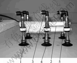
Fig.1 Photo of WALKMAN-I: 1��FPA; 2��Flexible pneumatic spherical joint; 3��Pipe connector; 4��Suction cups; 5��Rigid cover
2.2 Flexible pneumatic actuator FPA
FPA proposed by Zhejiang University of Technology consists of an elastic rubber tube, two covers and an air connector. The structure of FPA is shown in Fig.2. A spring embedded in the wall of rubber tube can not only restrain the tube��s deformation in radial direction but also enforce the stiffness of FPA. Each end of rubber tube is sealed by a cover. Under the high pressure of compressed air inside FPA, the rubber tube will expand. Because the spring restrains its deformation in radial direction, FPA will stretch in axial direction. When the FPA is deflated, it will return to its original state due to the elastoplasticity of rubber tube and the rebounding elasticity of spring.
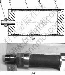
Fig.2 Structure (a) and photo (b) of FPA(1��Connector; 2, 5��Covers; 3��Rubber tube; 4��Spring)
In order to move on the wall surface, frictional force is required to sustain the robot upward on the wall. So, the mass of the climbing robot should be light. FPA generally has the advantages of low-cost, lightweight, no friction, higher stiffness, good flexibility and good power/mass ratio, and it is directly driven by compressed air. So, FPA is very suitable for using as the drive component of wall-climbing robot with the above characteristics.
BAO et al[29] proposed the flexible pneumatic actuator FPA and analyzed its static and dynamic characteristics. The static model of FPA can be expressed as
![]() (1)
(1)
where ��L is the linear deformation of rubber tube; tb is the original thickness of shell; Eb is the elastic module of FPA; patm is the atmospheric pressure; p is the air pressure in actuator; R is the average radius of actuator; and Lb is the original length of rubber tube.
Experiments were done to study the property of FPA. The experimental data basically agree with the theoretical data, with a small discrepancy, as shown in Fig.3.
2.3 Flexible pneumatic spherical joint
Fig.4(a) shows the structure of the flexible pneumatic spherical joint which is composed of three FPAs uniformly distributed by 120?. The working principle of the spherical joint is: if the pressure of compressed air in the three FPAs is adjusted properly, the three FPAs have different elongations, and then the joint can bend in different directions.
Based on FPA, ZHANG et al[25] designed the flexible pneumatic spherical joint and proposed the static
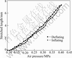
Fig.3 Experiment data of air pressure and stretched length of FPA (FPA parameters: Lb=25 mm; R=6 mm; tb=2 mm)
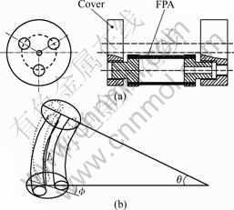
Fig.4 Flexible pneumatic spherical joint: (a) Structure of flexible pneumatic spherical joint; (b) Bending state of flexible pneumatic spherical joint
model. Fig.4(b) shows the bending state of the flexible pneumatic spherical joint. The static model is expressed as


![]() (2)
(2)
where ![]() is the abduction angle of the flexible pneumatic spherical joint; L0 is the original length of center line of the spherical joint; L1 is the length of FPAs that have pre-elongation; d is the distance between the axis of FPA and the axis of the spherical joint; Aw is the cross-sectional area of rubber shell of FPA; A1 is the cross-sectional area of gas room of FPA; pi is the air pressure in FPA; and �� is the bending angle.
is the abduction angle of the flexible pneumatic spherical joint; L0 is the original length of center line of the spherical joint; L1 is the length of FPAs that have pre-elongation; d is the distance between the axis of FPA and the axis of the spherical joint; Aw is the cross-sectional area of rubber shell of FPA; A1 is the cross-sectional area of gas room of FPA; pi is the air pressure in FPA; and �� is the bending angle.
3 Locomotion modes of WALKMAN-I
The motion of wall-climbing robot generally consists of a series of steps[30]. One step is composed of some action sequences generated by means of adhering mechanism and drive mechanism. WALKMAN-I has some kinds of locomotion modes. The basic locomotion modes and its advantages are discussed as follows.
In order to explain the modes clearly, three pairs of suction cups of WALKMAN-I are defined as: the frontal two suction cups, the middle two suction cups, and the rear two suctions.
3.1 Linear motion
Fig.5 shows the linear motion step sequences. When these step sequences are completed, WALKMAN-I advances by one step, which can be decomposed into the following substeps.
(a) Controller sends signals to open all the vacuum generators connected with suction sups, and then WALKMAN-I employs six suction cups to stick to the wall surface (see Fig.5(a)).
(b) Close the frontal two suction cups�� vacuum generators, and then the corresponding suctions cups are no longer in contact with the wall surface. So, WALKMAN-I is anchored by other four suction cups (see Fig.5(b)).
(c) Compressed air with the same pressure fills into three FPAs of the flexible pneumatic spherical joint, and then the joint will stretches along the axial direction, but does not bend in other direction. Due to the middle two suction cups and the rear two suction cups adhering to the wall surface, the frontal two suction cups will move one step forward (see Fig.5(c)).
(d) Controller sends signals to connect the frontal two suction cups�� vacuum generators and disconnect the middle two suction cups�� vacuum generators with air source, resulting in sucking and releasing the corresponding suction cups. This action sequences make WALKMAN-I anchored by the frontal two suction cups and the rear two suction cups (see Fig.5(d)).
(e) The pressure of compressed air in three FPAs reduces until the flexible pneumatic spherical joint returns to its origin state, and then compressed air fills into the PFA of WALKMAN-I. Under the high pressure of compressed air inside FPA, the FPA will expand. Because the middle two suction cups are not attached and the remaining four suction cups adhere to the wall surface, the middle two suction cups will move one step forward (see Fig.5(e)).
(f) Open the middle two suction cups�� vacuum generators, and then close the rear two suction cups�� vacuum generators. WALKMAN-I is attached to wall surface by means of the frontal and the middle two suction cups. When the FPA is deflated, the rear two suction cups will take a step, due to the elastoplasticity of rubber tube and the rebounding elasticity of spiral steel wire[22]. And then the whole body of WALKMAN-I will move one step forward (see Fig.5(f)).
Based on the above motion analysis, WALKMAN-I can easily move backward with changing the operating sequences of sticking-moving-sticking.
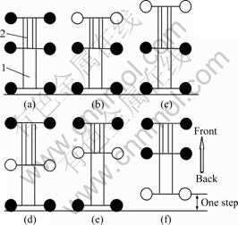
Fig. 5 Motion analysis of linear motion (top view): 1��FPA; 2��Flexible pneumatic spherical joint (���� is suction cup disconnected with wall surface, and ���� is suction cup adhering to wall surface)
3.2 Curvilinear motion
Advancing along a straight line, WALKMAN-I can change climbing direction. The action sequences of curvilinear motion are shown in Fig.6. The curvilinear movement step sequences are similar to the linear
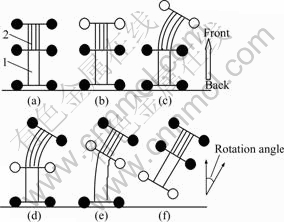
Fig.6 Motion analysis of curvilinear movement (top view): 1��FPA; 2��Flexible pneumatic spherical joint
movement step sequences. The difference between them is that the flexible pneumatic spherical joint not only acts as thruster, but also controls the climbing direction. Realization of WALKMAN-I curvilinear motion is controlled by adjusting bending angle of the flexible pneumatic spherical joint. The robot can rotate by 90? (maximum rotation angle) per step until reaching the desired posture.
3.3 Crossing orthogonal planes
The ability of crossing orthogonal planes is generally an important criterion to evaluate the dexterity of wall-climbing robot. WALKMAN-I is driven by FPA and the flexible pneumatic spherical joint mainly composed of rubber, which means that WALKMAN-I has advantages of good flexibility and great adaptability. These features make WALKMAN-I be superior to others.
The step sequences of WALKMAN-I crossing the orthogonal planes are shown in Fig.7. The sequences are similar to the linear movement step sequences. According to environment, the stretched length of the PFA, bending angle and bending direction of the flexible pneumatic spherical joint are adjusted in real-time. Matching with suction cups connected or disconnected with wall surface, WALKMAN-I can easily realize crossing orthogonal planes.
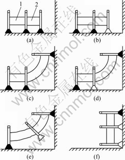
Fig.7 Motion analysis of crossing orthogonal planes (left view): 1��FPA; 2��Flexible pneumatic spherical joint (��![]() �� is suction cup disconnected with wall surface, and ��
�� is suction cup disconnected with wall surface, and ��![]() �� is suction cup adhering to wall surface)
�� is suction cup adhering to wall surface)
According to the analysis mentioned above, WALKMAN-I has three basic locomotion modes and its motion characteristics can be summarized as follows.
(1) When climbing on the wall surface, WALKMAN-I has four or more suction cups adhering to the surface. This can increase the suction force mostly, and raise the safety factor for WALKMAN-I.
(2) When the pressure of compressed air inside FPA and the flexible pneumatic spherical joint and frequency of deflating and inflating are adjusted properly, moving velocity and rotation angle of WALKMAN-I can be easily controlled.
(3) During the curvilinear movement, the offset of the center of gravity of WALKMAN-I results in eccentricity of suction cups.
(4) Because the center of gravity of WALKMAN-I is close to the wall surface, the suction force required is small.
4 Safety analysis
When a wall-climbing robot walks on a vertical wall, there are two types of dangers: slipping and falling from the wall surface, which might be caused by overload or other accidents. Although the slipping can be stopped by controlling the vacuum pressure in the suction cups, falling is fatal and must be avoided. Therefore, it is necessary to analyze the safety conditions, which are constraint conditions and foundation of structure design and motion control of the robot.
WALKMAN-I has three basic locomotion modes: linear motion mode, curvilinear motion mode, and crossing orthogonal plane mode. Crossing orthogonal planes mode is a complicated motion mode, which can be decomposed into combined linear motion and curvilinear movement. Therefore, we just analyze the safety conditions of linear and curvilinear motion modes.
4.1 Safety conditions of linear motion
When moving along a straight line, WALKMAN-I uses four suction cups to stick on the wall surface. This can be divided into three situations: (1) the frontal two suction cups are released, and the other four suction cups are sucked; (2) the rear two suction cups are released, the remaining four suction cups are sucked; (3) the middle two suction cups are released, and the other four suction cups are sucked.
In order to explain briefly and clearly, Figs.8-10 show the force diagrams of WALKMAN-I in three situations, respectively. The coordinate system is built, and x-axis, y-axis and z-axis are defined as follows.
The positive direction of x-axis is parallel to the wall surface upward, the positive direction of y-axis is perpendicular to wall surface inward, and z-axis is determined by right-hand rule. Point A in surface between the rear two suction cups is defined as the reference point.
The symbols in Figs.8-10 are defined as follows. G is the total mass of WALKMAN-I; fi is the friction force
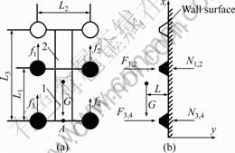
Fig.8 Force diagram of WALKMAN-I during linear motion in the first state: (a) Top view(1��FPA; 2��Flexible pneumatic spherical joint); (b) Left view
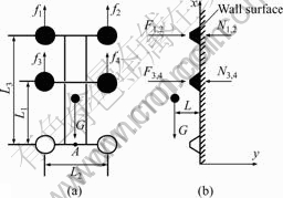
Fig.9 Force diagram of WALKMAN-I during linear motion in the second state: (a) Top view; (b) Left view
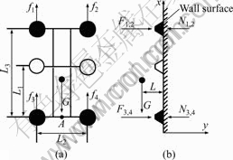
Fig.10 Force diagram of WALKMAN-I during linear motion in the third state: (a) Top view; (b) Left view
between suction cups and wall surface, i=1, 2, 3, 4; Fi is the suction force of suction cups produced by the vacuum generator, i=1, 2, 3, 4; Ni is the normal force (perpendicular to the wall surface), i=1, 2, 3, 4; L is the distance between wall surface and WALKMAN-I��s center of gravity; L1 is the span length between the rear two suction cups and the middle two suction cups; L2 is the distance between centers of suction cups in a level line; L3 is the span length between the frontal two suction cups and the rear two suction cups.
In the first situation, the force diagram of WALKMAN-I walking forward on the wall surface along the y-axis is shown in Fig.8. In order to avoid falling and slipping from the wall, WALKMAN-I must satisfy the force equilibrium and the moment equilibrium. The force equilibrium equation in the x-direction is
![]() (3)
(3)
The friction force between wall surface and the suction cups is less than the maximum static friction, so there is
![]() (4)
(4)
where �� is coefficient of static friction.
The force equilibrium equation in the y-direction can be derived as
![]() (5)
(5)
The suction force can be expressed as
F=vs (6)
where �� is vacuum pressure inside suction cups; s is suction area of the suction cups.
The models of the six suction cups are the same. So, the suction forces of the suction cups are the same. Then the following equation can be obtained:
F=F1=F2=F3=F4=vs (7)
Because WALKMAN-I is symmetric with respect to the center line, there are
f1=f2, f3=f4 (8)
N1=N2, N3=N4 (9)
The moment equilibrium equation about point A is
![]() (10)
(10)
Substituting Eqs.(7)-(9) into Eqs.(4)-(5) and (10), the following equations can be derived
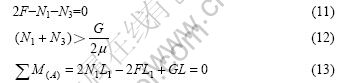
To avoid WALKMAN-I slipping and falling from the surface, the following inequations must be satisfied:
N1=N2��0, N3=N4��0 (14)
From Eqs.(12)-(14), the following inequations are derived

According to Eqs.(11)-(12) and (15), the condi- tions to avoid slipping and falling are given as follows. The safety zone is shown in Fig.11.
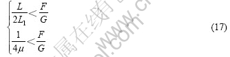
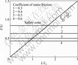
Fig.11 Safety zone of WALKMAN-I in linear motion
Figs.9-10 show the force diagrams of WALKMAN-I in the second and third situations during the linear motion. Then the corresponding safety conditions can be derived as follows:
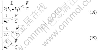
From the above analyses, WALKMAN-I should be designed under conditions (17)-(19). The safety conditions of WALKMAN-I climbing along a straight line have the following characteristics.
(1) Walking on the surface along a straight line, WALKMAN-I uses four suction cups to stick to the wall. The suction force of suction cups is equal to each other.
(2) L�� is defined as the span distance between suction cups sucked. If mass G of WALKMAN-I is assumed as a constant, when  , the minimum suction force F of the suction cups decreases with the increase of the coefficient of static friction ��, and has nothing to do with distances L and L��. When
  , the minimum suction force F is proportional to distance L, and inverse proportional to distance L��.
4.2 Safety conditions of curvilinear motion
Utilizing a flexible pneumatic spherical joint, WALKMAN-I can easily adjust its moving direction, as shown in Fig.6. When WALKMAN-I walks on the wall surface along a curved path, the center of gravity of WALKMAN-I always changes irregularly. It is complicated to analyze the safety conditions of curvilinear motion of WALKMAN-I, so we choose two typical states of motion to examine the safety conditions. Figs.12 and 13 show the force diagrams of WALKMAN-I in two states of curvilinear motion. The symbols in Figs.12 and 13 have the same meanings as defined in Fig.8.
Fig.12 shows the force diagram of WALKMAN-I in the first motion state. The flexible pneumatic spherical joint performing bending motion turns to right, which results in the offset of the center of gravity of WALKMAN-I which is defined as L4.
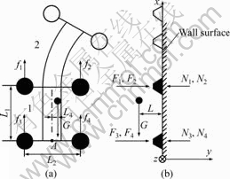
Fig.12 Force diagram of WALKMAN-I in the first state: (a) Top view(1��FPA; 2��Flexible pneumatic spherical joint); (b) Left view
According to Fig.12, the equilibrium equations are:
![]() (20)
(20)
![]() (21)
(21)
![]() (22)
(22)
![]()
![]() (23)
(23)
As mentioned above, the following inequations and equation must be fulfilled:
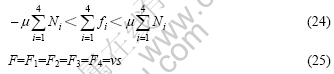
From Fig.12, the suction cups sucked are symmetric with respect to the center line. Substituting Eqs.(21), (24) and (25) into Eqs.(20) and (22), we have
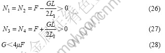
Substituting Eqs.(21) and (24) into Eq.(23), we can derive
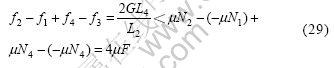
From Eq.(29), the following inequation can be derived:
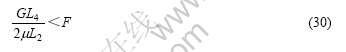
According to Eqs.(26)-(30), the safety conditions in the first state can be expressed as
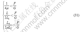
According to Eq.(31), we can find that when mass G, distance L2 and coefficient of static friction �� are constant, and the inequation max![]() is
is
satisfied, the minimum suction force F of suction cups increase with the increase of the offset L4 of center of gravity of WALKMAN-I.
Fig.13 shows the force diagram of WALKMAN-I in the second state, which has completed the curvilinear motion with rotation angle ��.
In the similar manner, one of safety conditions can be derived: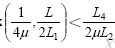 . According to Fig.13, the
following moment equilibrium equations must be satisfied to avoid falling and slipping from the wall:
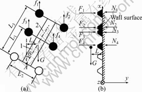
Fig.13 Force diagram of WALKMAN-I in the second state: (a) Top view(1��FPA; 2��Flexible pneumatic spherical joint); (b) Left view
![]()
![]()
![]()
![]() (32)
(32)
![]()
![]()
![]()
![]() (33)
(33)
From Eqs.(32) and (33), we can find the safety conditions of WALKMAN-I during the curvilinear motion are very complicated. So, its characteristics will be measured by experiments.
5 Experiments and analyses
5.1 Control system
WALKMAN-I basically consists of a flexible pneumatic actuator FPA, a flexible pneumatic spherical joint, and six suction cups. So, FPA, the flexible pneumatic spherical joint and the suction cups are controlled coordinately, which can realize WALKMAN-I��s control.
The schematic diagram of WALKMAN-I��s control system is shown in Fig.14.
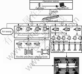
Fig.14 Schematic diagram of WALKMAN-I��s control system
As shown in Fig.14, three FPAs of the flexible pneumatic spherical joint and the FPA of WALKMAN-I are connected with four electro-pneumatic regulators, which can adjust output air pressure that is proportional to the input analog signal. So the compressed air flowing out from the electro-pneumatic regulator will inflate the FPAs. The six suction cups are connected with six vacuum generators controlled by three solenoid valves. The working principle of control system is as follows. The operator sends out control commands, and then the industrial personal computer (IPC) calculates the motion parameters that are sent to the control card by RS485. According to the motion parameters, the control card sends four-channel analog voltage signals by D/A converters and three-channel digital switching signals, which adjust the air pressure inside the FPA, changes the bending angle of the flexible pneumatic spherical joint and controls the action sequences of sticking-moving- sticking respectively. When the above steps are completed, the motion of WALKMAN-I can be controlled.
5.2 Experiments
WALKMAN-I was designed. Furthermore, experiments were carried out to verify the locomotion modes proposed. The experimental specifications of WALKMAN-I climbing on the wall surface are given in Table 1. Figs.15-17 show that WALKMAN-I is walking along a straight line and curved path, and crossing the orthogonal planes respectively.
Table 1 Experimental specifications of WALKMAN-I
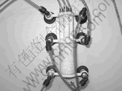
Fig.15 Photo of WALKMAN-I doing linear motion
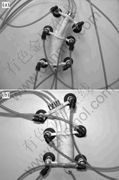
Fig.16 Photos of WALKMAN-I doing curvilinear motion: (a) Turn right; (b) Turn left
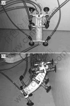
Fig.17 Photos of WALKMAN-I crossing orthogonal planes: (a) Top view; (b) Left view
6 Conclusions
(1) Based on the FPA and the flexible pneumatic spherical joint, a flexible pneumatic wall-climbing robot WALKMAN-I is proposed. It can realize linear movement, curvilinear movement and crossing orthogonal planes.
(2) The safety conditions of linear motion and curvilinear motion of WALKMAN-I are analyzed.
(3) The control system is built, and the locomotion modes of WALKMAN-I are confirmed by the experiments. Experimental results show that when the air pressure inside FPA and the flexible pneumatic spherical joint and frequency of deflating and inflating are adjusted properly, the moving velocity and rotation angle of WALKMAN-I can be easily controlled.
(4) The CCD camera can be installed on the WALKMAN-I. So, the robot can be oriented easily.
References
[1] SUN D, ZHU J, LAI C M, TSO S K. A visual sending application to a climbing cleaning robot on the glass surface[J]. Mechatronics, 2004, 14(1): 1089-1104.
[2] NISHI A. Development of wall-climbing robot[J]. Computers & Electrical Engineering, 1996, 22(2): 123-149.
[3] BALAGUER C, GIMENEZ A, PASTOR J M, PADRON V M, ABDERRAHIM M. Climbing autonomous robot for inspection applications in 3D complex environments[J]. Robotica, 2000, 18(3): 287-297.
[4] LAROSA G, MESSINA M, MUSCATO G, SINATRA R. A low-cost lightweight climbing robot for the inspection of vertical surfaces[J]. Mechatronics, 2002, 12(1): 71-96.
[5] XIAO Xiao-hui, WU Gong-ping, DU E, SHI Tie-lin. Dynamic simulation and experimental study of inspection robot for high-voltage transmission-line[J]. Journal of Central South University of Technology, 2005, 12(6): 726-731.
[6] DAVE M. Potential use of walking and climbing robots in nuclear facilities[J]. Nucl Engr, 2001, 42(1): 4-8.
[7] ZHU J, SUN D, TSO S K. Development of a tracked climbing robot[J]. J Intell Robot Syst, 2002, 35(4): 427-444.
[8] ELKMANN N, FELSCH T, SACK M, BOEHME T, HORTIG J, SAENZ J. Modular climbing robot for service-sector applications[J]. Ind Robot, 1999, 26(6): 460-465.
[9] ZHAO Xin-fen, ZHOU Yi, SHI Chong-hui. Development of pneumatic wall-climbing robot[J]. Machine Tool & Hydraulics, 2003(3): 61-62. (in Chinese)
[10] LIU Shu-xia, WANG Yan, XU Dian-guo. The application of wall-climbing robot[J]. Robot, 1999, 21(2): 148-155. (in Chinese)
[11] XIAO Li, TONG Ren-zhong, DING Qin-min, WU Jun-sheng. The current situation and development of the wall-climbing robot[J]. Automation Panorama, 2005(1): 81-84. (in Chinese)
[12] GUO Cheng, TAN Shi-li, WENG Sheng-long. The key technology of micro wall-climbing robot research[J]. Manufacturing Automation, 2004, 26(7): 21-24. (in Chinese)
[13] GRIGORE C, BURDE A, COIFFET P. Virtual real technology[M]. New York: Wiley John & Sons, Incorporated, 2005.
[14] ZHANG Ke, WU Yi-xiong, L? Xue-qin, JIN Xing. Dynamic modeling and simulation for nonholonomic welding mobile robot[J]. Journal of Central South University of Technology, 2007, 14(5): 679-684.
[15] ZHOU Yi, CHEN Pei-fu, YU Jin. Design of light and multi-foot wall-climbing robot[J]. Machine Tool and Hydraulics, 2006(7): 77-79. (in Chinese)
[16] HUANG Shan-jun. Research on wall-climbing robot[D]. Harbin: Harbin Institute of Industry, 1990. (in Chinese)
[17] AKIHIKO N, SHIGEO H. Walking and running of the quadruped wall-climbing robot[C]//Proceedings of the IEEE International Conference on Robotics and Automation. San Diego: IEEE Press, 1994: 1005-1012.
[18] HIROSE S, KAWABE K. Ceiling walk of quadruped wall climbing robot NINJA-II[C]//Proceedings of the First International Conference CLAWAR 98. Bury St Edmunds: Professional Engineering Publishing, 1998: 143-147.
[19] MEL S. Robotic assistance for air inspectors[J]. Industrial robot, 1998, 25(6): 389-400.
[20] XU W L, ZONG G H, TSO S K. An autonomous mobile robot for glass-wall cleaning[C]//3rd IFAC Symposium on Intelligent Autonomous Vehicles. Chicago: Pergamon Press, 1998: 25-27.
[21] XU D, LIU S, ZHOU D, WANG Y. Design of a wall cleaning robot with a single suction cup[C]//Proceedings of the Second International Conference CLAWAR 99. Portsmouth, 1999: 405-411.
[22] YANG Qing-hua, ZHANG Li-bin, BAO Guan-jun, RUAN Jian. Pneumatic squirming robot based on flexible pneumatic actuator[C]//Proceedings of SPIE ICMIT2005, Control Systems and Robotics. Chongqing, 2005: 60422w-1-60422w-5.
[23] ZHANG Li-bin, BAO Guan-jun, YANG Qing-hua, RUAN Jian, QI Li-yong. Static model of flexible pneumatic bending joint[C]// Proceeding of the 2006 9th Int Conf Control, Automation, Robotics and Vision. Singapore, 2006: 1749-1753.
[24] YANG Qing-hua, CHEN Gang, ZHOU Quan. Investigation on the model of a new type of bending joint[J]. Journal of Zhejiang University of Technology, 2003, 31(1): 92-96. (in Chinese)
[25] ZHANG Li-bin, BAO Guan-jun, YANG Qing-hua, RUAN Jian. Fuzzy-PID control for flexible pneumatic spherical joints[J]. China Mechanical Engineering, 2005, 16(5): 407-409. (in Chinese)
[26] YANG Qing-hua, ZHANG Li-bin, XU Sheng. Pneumatic squirming robot[J]. Hydraulics and Pneumatics, 2004, (5): 44-46. (in Chinese)
[27] SUN Jin-shan, YANG Qing-hua, RUAN Jian. Pneumatic multi-suckered wall-climbing robot[J]. Hydraulics and Pneumatics, 2005, (8): 56-59. (in Chinese)
[28] YANG Qing-hua, BAO Guan-jun, WANG Zhi-heng, SHOU Hua-liang, ZHANG Lin-bin. Development of new kind of pneumatic wall-climbing robot[C]//The 5th International Symposium on Fluid Power Transmission and Control. Beidaihe, 2007: 16-25.
[29] BAO Guan-jun, YANG Qing-hua, RUAN Jian, ZHANG Li-bin. Research on static characteristics of flexible pneumatic actuator FPA[C]//The 5th International Symposium on Fluid Power Transmission and Control. Beidaihe, 2007: 145-150.
[30] ZHANG Pei-feng, WANG Hong-guang, FANG Li-jing, JIANG Yong. Mechanism and kinematics of a novel climbing robot[J]. Robot, 2007, 29(1): 12-18. (in Chinese)
Foundation item: Project (50575206) supported by the National Natural Science Foundation of China; Project (BX102716) supported by Xinmiao Program of Zhejiang Province, China
Received date: 2008-12-26; Accepted date: 2009-04-21
Corresponding author: YANG Qing-hua, Professor; Tel: +86-571-88320819; E-mail: robot@zjut.edu.cn
