
Trans. Nonferrous Met. Soc. China 29(2019) 1184-1199
A novel method to improve interfacial bonding of compound squeeze cast Al/Al-Cu macrocomposite bimetals: Simulation and experimental studies
Mohammad Hossein BABAEE1, Ali MALEKI2, Behzad NIROUMAND1
1. Department of Materials Engineering, Isfahan University of Technology, Isfahan 84156-83111, Iran;
2. Department of Mechanical Engineering, Isfahan University of Technology, Isfahan 84156-83111, Iran
Received 16 July 2018; accepted 4 March 2019
Abstract:
A facile and innovative method to improve bonding between the two parts of compound squeeze cast Al/Al-4.5wt.%Cu macrocomposite bimetals was developed and its effects on microstructure and mechanical properties of the bimetal were investigated. A special concentric groove pattern was machined on the top surface of the insert (squeeze cast Al-4.5wt.%Cu) and its effects on heat transfer, solidification and distribution of generated stresses along the interface region of the bimetal components were simulated using ProCAST and ANSYS softwares and experimentally verified. Simulation results indicated complete melting of the tips of the surface grooves and local generation of large stress gradient fields along the interface. These are believed to result in rupture of the insert interfacial aluminum oxide layer facilitating diffusion bonding of the bimetal components. Microstructural evaluations confirmed formation of an evident transition zone along the interface region of the bimetal. Average thickness of the transition zone and tensile strength of the bimetal were significantly increased to about 375 ��m and 54 MPa, respectively, by applying the surface pattern. The proposed method is an affordable and promising approach for compound squeeze casting of Al-Al macrocomposite bimetals without resort to any prior cost and time intensive chemical or coating treatments of the solid insert.
Key words:
Al/Al-4.5wt.%Cu macrocomposite bimetal; interfacial bonding; surface machining pattern; microstructure; mechanical properties; simulation;
1 Introduction
Industrial demands for lightweight constructions have been continually increasing in recent years leading to an extensive boost in use of aluminum and its alloys. Aluminum and its alloys have found many applications in automotive, aerospace and marine industries. This is attributed to the fact that monolithic aluminum components benefit greatly from such promising features as excellent thermal and electrical conductivity, high specific strength and modulus, superior resistance to corrosion and good castability [1-3]. Nonetheless, any specific aluminum alloy may not satisfy all the engineering and industrial requirements of a specific component. One demonstrated that solution for this problem is use of bimetallic components [4,5]. Bimetals are hybrid macrocomposites providing optimum combinations of the required mechanical, physical, chemical, thermal, electrical or magnetic characteristics of different materials which are not met by any of the individual materials separately [4-7].
Many ferrous and nonferrous metals and alloys are being widely utilized to fabricate multilayered structures. Lightweight bimetallic constructions such as Al-Al, Al-Mg and Mg-Mg joints have attracted great attentions in recent decades [4,7-9]. One of the major routes for manufacturing of Al-Al bimetals is compound casting [4]. This process is a solid-liquid bonding method in which a metallic melt is poured over or around a solid metal substrate (insert) embedded in a die forming a proper metallurgical transition zone between the two parts. Compound casting provides a relatively simple and beneficial approach to manufacture as cast Al-Al bimetals without any geometrical and dimensional restrictions [4,9,10].
In spite of the abovementioned capabilities of compound casting, aluminum alloys are difficult to bond by compound casting process due to the presence of a thermally stable aluminum oxide layer on the surface of aluminum insert which inhibits formation of a diffusion zone along the interface region [4,9-13]. In order to tackle this issue, researchers have proposed a variety of methods to remove this detrimental surface oxide layer and replace it by a reactive metallic coating [9,11-13]. Among all metallic coating materials, zinc has the greatest potential to form a continuous transition zones along the interface region. This is due to its low melting point (about 420 ��C), high solubility in aluminum at elevated temperatures and sufficient wettability in contact with molten aluminum alloys [14-18]. Different combinations of compound cast Al-Al bimetals have been prepared by researchers through some preliminary chemical and coating treatments on the solid insert [14-20]. Generally, surface of solid aluminum insert is first cleaned by some special pretreatments to get rid of the oxide layers, other surface contaminations and lubricant residues. The naturally occurring surface oxide layer is then chemically removed and replaced with a zinc layer using zincate treatment followed by zinc electroplating procedure. This procedure is cost and time intensive and un-ecofriendly [14,15].
In an earlier study by the authors [21], attempts were made to fabricate a compound squeeze cast Al/Al-4.5wt.%Cu macrocomposite bimetal without resorting to any surface coating. In that work, surface of the insert (squeeze cast Al-4.5wt.%Cu alloy) was mechanically ground with 180 grit sandpaper to an average surface roughness (Ra) of 0.615 ��m and the interfacial interactions between the two parts of the bimetal were studied by experimental and simulation investigations. The results indicated no detectable change in microstructure of the insert alloy and no obvious diffusion of copper across the interface of bimetal components. Simulation results were in good agreement with the experimental ones only when an equivalent oxide layer was considered along the interface. This oxide layer reduced the heat transfer across the interface and caused up to 50% drop in the liquid fraction formed on the surface of the insert during process. Furthermore, simulation of the generated stresses at the interface showed uniform distribution of rather small compressive thermal and mechanical stresses normal to the interface resulting in perseverance of the interfacial oxide layer during the manufacturing process. It was concluded that due to high reoxidation susceptibility of aluminum insert alloy, mechanical abrasion of the insert surface could not get rid of the detrimental oxide layer. This led to poor bonding between the bimetal components [21].
One could presume that even the shortest delay between removing the oxide layer and pouring the melt on the insert would provide reoxidation of the insert surface. Therefore, the best solution for a successful interfacial bonding is one in which removal of the oxide layer occurs simultaneously as the melt pouring.
To the best of the authors�� knowledge, no research has been reported so far on manufacturing of Al-Al bimetals without any extensive prior chemical or coating treatments on the insert surface. Therefore, in this study, a facile and innovative method for improving the bonding between components of a compound squeeze cast Al/Al-4.5wt.%Cu macrocomposite is developed and its effects on microstructure, mechanical properties, heat transfer, solidification and generated stresses along the interface region of the produced bimetal are investigated.
2 Experimental
2.1 Materials
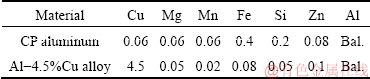
In order to prepare Al/Al-Cu macrocomposite bimetals, Al-4.5wt.%Cu alloy and commercially pure (CP) aluminum were employed as the solid insert alloy and the poured melt, respectively. Table 1 presents chemical compositions of the materials used in this study.
Table 1 Chemical compositions of materials used (wt.%)
High specific strength after heat treatment is among the most significant characteristics of cast and wrought Al-Cu alloys [22]. But these alloys are susceptible to intergranular, pitting and exfoliation corrosions [23-26] and have poor weldability by conventional fusion welding routes [26,27]. Pure aluminum, on the other hand, is a good corrosion and oxidation resistance material [1,3]. Manufacturing of CP Al/Al-Cu bimetals with good interfacial metallurgical bonding can be a new approach to get a combination of high specific strength and corrosion resistance.
2.2 Manufacturing of macrocomposite bimetals
CP Al/Al-4.5wt.%Cu macrocomposite bimetals were manufactured using a squeeze casting die set up and the procedure reported elsewhere [21]. The inner diameter and height of the heat treated hot work tool steel (H13) die used were about 100 and 90 mm, respectively, and the inner surfaces of the die were coated with a water-based graphite coating prior to each test.
First, based on the previous experiences of the authors [21,28-33] and some preliminary trials, Al-4.5wt.%Cu cylindrical inserts (diameter of 100 mm and height of (25��1) mm) were prepared by squeeze casting at pouring temperature of 750 ��C, die preheating temperature of 250 ��C and external pressure of 70 MPa. Squeeze cast Al-4.5wt.%Cu solid inserts were then washed, degreased and rinsed with distilled water and ethanol. A special concentric groove pattern with depth of 1 mm and spacing of about 2 mm was subsequently machined on the top surface of the insert (Fig. 1(a)).
The surface machined solid insert was then located at the bottom of the die cavity and the die set up was preheated to 350 ��C using a temperature controlled electric heater. Afterwards, about 600 g of molten CP aluminum ingot was poured over the solid insert. The pouring temperature and time were 800 ��C and 4 s, respectively. Then, the punch was lowered and came in contact with the free surface of the liquid aluminum within around 6 s applying a 70 MPa of pressure during solidification of the upper part of the bimetal. The pressure was kept for about 5 min to ensure proper bonding of the two aluminum components. Finally, the punch was retracted to its original position and the solidified bimetal with diameter of 100 mm and height of (45��2) mm was ejected, trimmed and cut in half for further microstructural and mechanical assessments. These compound squeeze cast samples are named ��patterned bimetals�� throughout the paper in distinction with the previous compound cast samples, i.e. ��flat bimetals�� in which the insert top surface was only ground by sandpaper (Fig. 1(b)).
Figure 2 demonstrates actual and schematic illustrations of an Al/Al-Cu macrocomposite bimetal manufactured in this study. The results are compared with those of the flat bimetals presented previously [21].
2.3 Simulation of manufacturing process
Heat transfer, solidification sequence and distribution of generated stresses along the interface region of the bimetal during the manufacturing process were modeled using ProCAST 2016 and ANSYS R17.0 simulation softwares. The results would provide a better understanding of the influences of interfacial phenomena upon the interface microstructure.
Heat transfer and solidification sequence of the patterned bimetal were simulated using ProCAST software. An optimized 200 ��m planimetric mesh was utilized for the interface region of the bimetal [21]. The squeeze casting die, bimetal components and the interface region were volumetrically meshed as presented in Fig. 3. The numbers of two dimensional (triangular type) and three dimensional (tetrahedral type) meshes were 198792 and 5738348, respectively.
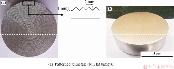
Fig. 1 Squeeze cast Al-4.5wt.%Cu insert alloys and their surface conditions prior to compound casting
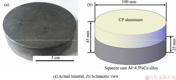
Fig. 2 Manufactured Al/Al-Cu macrocomposite bimetal
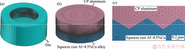
Fig. 3 Finite element mesh of die (a), bimetal components (b) and interface region (c)
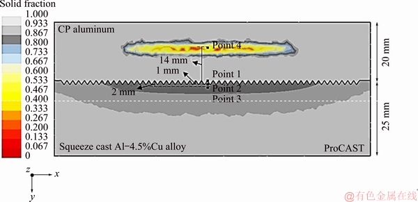
Fig. 4 Four selected points of bimetal parts where variations of temperature and solid fraction versus time were simulated
CP aluminum melt (800 ��C) was poured over the insert alloy placed inside the die (both preheated to 350 ��C) at a flow rate (inlet) of 113.5 g/s within 4 s. Temperature and solid fraction changes of the bimetal parts with time were then simulated at 4 selected points (Fig. 4). Points 1 to 3 were 0, 1 and 2 mm away from the tips of the concentric machining pattern to depth of the Al-4.5wt.%Cu insert alloy, respectively. Point 4 was selected at the center of the hot spot of CP aluminum part where the solidification time was the longest.
Many researchers have shown that magnitude of applied pressure affects the heat flow across the interface of a solidifying metal and a die [34-36]. Despite these attempts, no generally accepted relationship to quantify this correlation has been proposed yet. Therefore, in this study, the heat transfer coefficient values were chosen based on findings of other researchers. Convective heat transfer coefficients for simulation of interfacial heat flow across the CP aluminum and the die wall, the CP aluminum and air/punch as well as the CP aluminum and the solid insert were extracted from the work of NISHIDA and MATSUBARA [37] and ProCAST software database [38].
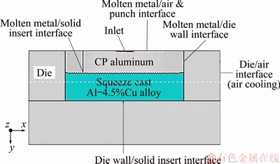
Fig. 5 Different interfaces in simulation of heat transfer of bimetal
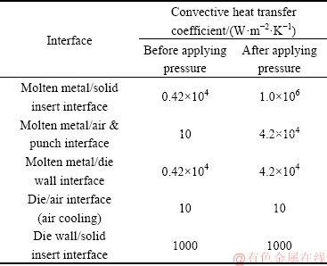
Figure 5 and Table 2 indicate the boundary conditions and the interfacial heat transfer coefficients chosen for different interfaces before and after applying the pressure. Interfacial heat transfer coefficients of the die/air and the die wall/solid insert alloy are considered to remain constant during the manufacturing process [38]. Correlation between convective thermal resistance and heat transfer coefficient can be basically explained by Eq. (1) [39], where Rconv (K/W), hconv (W/(m2��K) and As (m2) are convective resistance to heat flow, convective heat transfer coefficient and heat transfer surface area, respectively.
 (1)
(1)
Due to the large applied vertical pressure (external and metallostatic pressures), an intimate contact between the two bimetal parts is realized and, as a result, the interfacial resistance to heat transfer (Rconv) was assumed to be relatively negligible. Therefore, heat transfer coefficient (hconv) must be regarded sufficiently greater than other given values in Table 2. Due to lack of any accurate value in the literature, convective heat transfer coefficient of 1.0��106 W/(m2��K) was employed along the interface region of the bimetal.
Table 2 Interfacial heat transfer coefficients before and after applying external pressure [37,38]
Magnitude and distribution of the total and equivalent stresses (von Mises stresses) generated along the interface region of the bimetals were evaluated using ANSYS simulation software. For this purpose, a longitudinal element with upper dimensions of 100 mm �� 1 mm was selected along the bimetal interface. This element is made of two different components including a solid aluminum alloy at preheating temperature of 350 ��C and a pure aluminum melt at 800 ��C. Then, an optimum 0.4 mm planimetric mesh was used for both of the mentioned bimetal parts as illustrated in Fig. 6. The number of 2D (triangular type) meshes was equal to 42565. Moreover, a 7000 N steady-state compressive load corresponding to the external pressure used for manufacturing of the bimetals was applied on the top surface of the element. Figure 7 shows a high magnification view of the element as well as the location of the 7000 N compressive load.
2.4 Characterization of microstructure and mechanical properties
Microstructural analyses were performed following standard metallographic practices [40]. Optical microscope (OM-Nikon EPIPHOT300), scanning electron microscope (SEM-Seron AIS2300C) and energy dispersive X-ray spectroscope (EDS-Seron AIS2100) were utilized to evaluate microstructure of the interface region of the manufactured bimetals.
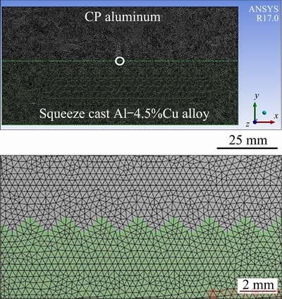
Fig. 6 Finite element mesh of element taken along bimetal interface
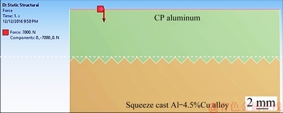
Fig. 7 Location of 7000 N steady-state compressive load applied on upper surface of longitudinal element
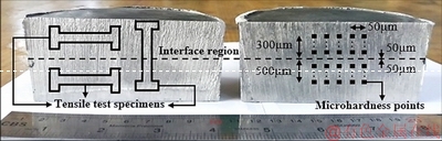
Fig. 8 Manufactured compound squeeze cast Al/Al-Cu macrocomposite bimetal cut into two halves for microstructural and microhardness evaluation
Figure 8 depicts two halves of a manufactured and sectioned Al/Al-Cu macrocomposite bimetal and schematically demonstrates the approximate locations where the tensile test specimens were cut and microhardness was measured. In this figure, distances of the nearest and furthest microhardness measurement points from the interface region are indicated for each half. The spacing between the horizontal indentation marks was about 50 ��m and the average of five measurements at any given distance from the interface was reported as the microhardness value at that distance as shown in Fig. 8. Variation ranges of the measurements are also given by error bars in the subsequent graphs. Microhardness data of the manufactured bimetal were measured across the interface by means of a Koopa MH3 hardness tester using a Vickers indenter at a load of 0.05 kg and dwell time of 10 s.
Moreover, tensile test specimens cut from the interface region as well as the CP aluminum and the insert parts (Fig. 8) were machined to dimensions shown in Fig. 9. The tests were performed using a STM-150 KN tensile test machine at a cross head speed of 1 mm/min at ambient temperature. It should be noted that the tensile properties reported in this study are the average of three tests for each sample and variation ranges of the results are specified by error bars in the following graphs.
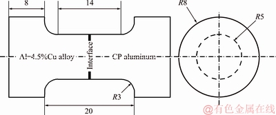
Fig. 9 Schematics of bimetallic tensile test specimens (unit: mm)
3 Results and discussion
In earlier part of this study [21], top surface of the inserts was ground by sandpaper just before compound squeeze casting process (flat bimetal) to remove the surface oxide layer and diminish its negative effects on heat transfer across the interface. The results showed ineffectiveness of the surface grinding due to rapid reformation of the oxide layer during the subsequent treatments. Stress analysis also showed that thermal and mechanical induced stresses at the bimetal interface could not break up this newly formed oxide layer.
In this part of the study an innovative simple solution for overcoming the problems associated with the interfacial oxide layer was examined. The idea behind this solution was to generate large enough in-situ thermal and mechanical stress gradient fields on the insert surface during bimetal manufacturing to break up and discontinue the harmful surface oxide layer on top of the insert. This would provide direct metal-metal contact at the interface and facilitate diffusion bonding of the two parts without resort to any extensive chemical or coating treatments of the solid insert.
This was accomplished by applying the described machining pattern on the insert top surface. In the subsequent sections the simulation and experimental findings for the patterned bimetals are frequently compared to those of the flat bimetals.
3.1 Simulation of solidification and heat transfer
Assuming a surface pattern on the top surface of the insert alloy as shown in Fig. 1(a), mold filling and changes of solid fraction in both the CP aluminum and the insert of the patterned bimetal were modeled using ProCAST 2016 simulation software. According to ProCAST software, non-equilibrium solidus and liquidus temperatures of the lower part of the bimetal, i.e. the Al-4.5wt.%Cu insert, are around 547 and 648 ��C, respectively [38]. Ten different time steps of the simulation are illustrated in Fig. 10. As it is obvious from Figs. 10(a-c), during the mold filling period (first 4 s) while molten CP aluminum is continuously supplied to the die, no solidification takes place. It seems that during this period of time, the heat input from the incoming molten CP aluminum balances the heat transfer to the die wall and the solid insert in such a way that the temperature of the molten part remains principally above its melting temperature (660 ��C) inhibiting any progress of solidification. Consequently, only heat flow through the die and the insert occurs.
Furthermore, no change in solid fraction of the insert alloy during the first 4 seconds of manufacturing process is evident from Figs. 10(a-c). In other words, during this period although the insert is being heated up by the heat transfer from the poured CP aluminum melt, its interface temperature is still lower than the solidus temperature of Al-4.5wt.%Cu alloy (547 ��C). This trend is exactly the same as the simulation results of the flat bimetal [21].
Figure 10(d) indicates a directional solidification front arising towards the center of the CP aluminum part at 10 s after the initiation of pouring, i.e. just when the punch is coming in contact with the free surface of the melt. It also shows that up to this time, the Al-4.5wt.%Cu insert has remained completely solid.
Upon contact of the punch with free surface of the molten metal, a new downward solidification front from the top of the insert is formed (Fig. 10(e)). Moreover, applying 70 MPa pressure at the 10th second of the manufacturing process leads to an abrupt increase in the heat transfer coefficient along all the interfaces (Table 2). As a result, solidification towards the hot spot of the CP aluminum part progresses at a much faster rate and finishes in about 6.8 s, i.e. 16.8 s from the beginning of the process (Figs. 10(d-i)). This time was 7.1 s for the flat bimetal [21]. This is thought to be due to the increased rate of heat flow from the molten metal to the solid insert by applying the surface machining pattern.
Figures 10(e-i) also show that the solid insert starts to melt at its surface concurrent with solidification of the CP aluminum owing to release of the latent heat of solidification of the CP aluminum part. Simultaneously, surface liquid fraction of the insert increases up to maximum value of 1 at the 10th second of the manufacturing process. So a mushy zone is formed from the interface region to a certain depth of the solid insert. Finally, solidification of melted zone of the Al-4.5wt.%Cu insert is completed after 25.08 s from the start of the process (Fig. 10(j)). The corresponding time for the flat bimetal was computed to be 25.8 s [21].
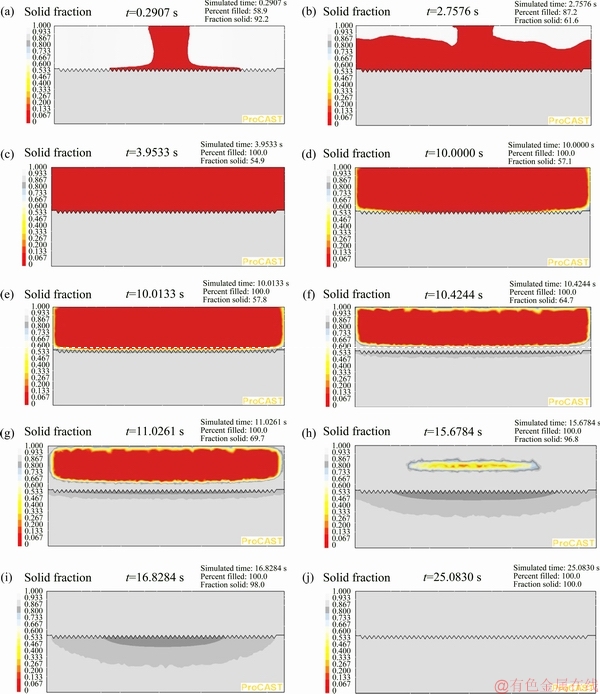
Fig. 10 Ten different progressive steps after start of pouring molten CP aluminum in die for manufacturing patterned bimetal based on simulation results by ProCAST software
Figure 11 shows temperature-time and solid fraction-time curves of the four selected points indicated in Fig. 4. This figure demonstrates that during the first 10 s of the manufacturing process of the patterned bimetal, temperature at point 1 (located on tip of the concentric machining pattern) is increased from 350 ��C to about 440 ��C with an average heating rate of about 9 ��C/s. Considering the solidus temperature of the insert alloy (547 ��C), solid fraction of the insert during this time period has not changed yet. As the external pressure is applied at the 10th second of the process, the interfacial heat transfer coefficients increase dramatically (Table 2). At the same time, the latent heat of solidification of the CP aluminum melt is released. Consequently, as shown in Fig. 11, temperature and liquid fraction of point 1 are suddenly increased to the maximum value of nearly 660 ��C and 1, respectively. The corresponding simulation results for the flat bimetal showed a maximum insert surface liquid fraction of 0.3 under similar compound casting conditions [21]. This can be attributed to increase in the specific surface area, transferred heat flux through the interface region as well as local thermal concentration on the tips of the grooves in the patterned bimetal.
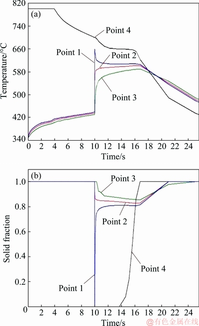
Fig. 11 Simulated temperature-time (a) and solid fraction-time (b) curves for four selected points of patterned bimetal shown in Fig. 4
Besides, the maximum temperature and liquid fraction of the patterned bimetal at points 2 and 3 reach about 600 ��C and 0.175 and 590 ��C and 0.155, respectively. Temperature-time and solid fraction-time variations of the hottest point of the CP aluminum part, i.e. point 4, show that temperature is decreased down to 700 ��C at an average cooling rate of about 10 ��C/s prior to application of pressure. The solid fraction-time curve at point 4 reveals solidification time of 3 s, i.e. from 13.8 to 16.8 s of the process. Location of point 4 is 14 mm from the interface (Fig. 4). The corresponding distance for the flat bimetal was 13 mm [21]. In other words, due to increased heat flow across the interface region, the hottest point of the CP aluminum part is moved upward by 1 mm when a concentric groove pattern is machined on the insert surface.
3.2 Microstructural evaluation of insert and its interface region
To assess the validity of the simulation results, microstructures of the Al-4.5wt.%Cu insert and the bimetal interface were analyzed and possible variations in the microstructures during the manufacturing process were investigated.
Figure 12 illustrates as-squeeze-cast microstructure of the Al-4.5wt.%Cu insert. As can be seen, the microstructure is comprised mainly of relatively fine uniform equiaxed dendrites of primary a(Al) phase enclosed by a low melting point eutectic structure of a(Al) and Al2Cu at the interdendritic regions.
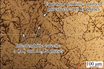
Fig. 12 As-squeeze-cast microstructure of Al-4.5wt.%Cu insert alloy
Using Thermo-Calc software, it was shown previously that under non-equilibrium solidification conditions, microstructure of an Al-4.5wt.%Cu alloy solidified under 70 MPa external pressure would include 89% dendritic grains of proeutectic ��(Al) phase and 11% interdendritic eutectic phases of ��(Al) and Al2Cu [21]. On the other hand, ProCAST simulation results predicted that, when the effect of the interfacial oxide layer on heat transfer was ignored, liquid fraction on the surface of the flat and patterned bimetals reached about 0.3 and 1, respectively.
Accordingly, for a flat bimetal one would expect complete melting of the interdendritic eutectic phases as well as partial melting of the primary proeutectic ��(Al) dendrites at the interface region. For a patterned bimetal, however, complete melting of both the interdendritic eutectic phase and primary ��(Al) phase is expected to be achieved at the interface. Under such circumstances, some evident microstructural changes on the insert upper surface of both bimetals seem inevitable.
Careful microstructural examinations of the flat bimetal showed no evidence of melting and solidification of the insert top surface during the manufacturing process and revealed no transition zone across the interface of the bimetal. Furthermore, very sharp increase in copper content and hardness across the interface region of the flat bimetal, from the CP aluminum part to the Al-4.5wt.%Cu insert alloy, suggested no or very limited diffusion of copper across the interface of the flat bimetal [21].
The discrepancy between the simulation and experimental results led to definition of an equivalent surface oxide layer on the insert surface. Considering the effects of such oxide layer in heat transfer and solidification simulations, the maximum liquid fraction on the insert surface was declined by 0.15 which was in acceptable agreement with the microstructural observations. Local liquid fraction of 0.15 is almost restricted to melting of interdendritic regions of the squeeze cast insert. As a result, as verified by the microstructural results, insignificant changes in the dendritic microstructure of the insert would be expected during the manufacturing process of the flat bimetal [21].
As-polished (unetched) optical micrographs from the interface region of the patterned bimetal are shown in Fig. 13, where formation of some scattered porosities in the insert side of the interface can be easily seen. The shape of the porosities suggests that they are of shrinkage type.
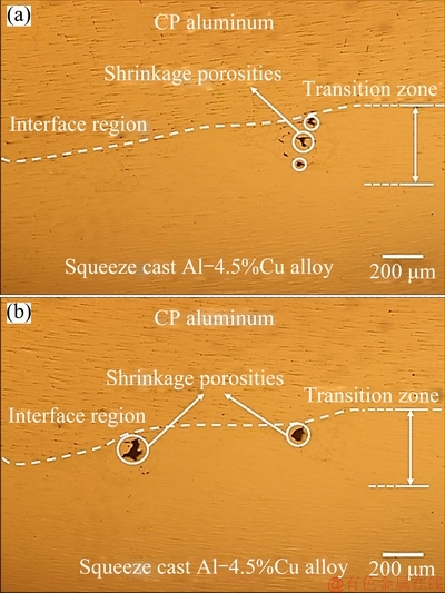
Fig. 13 Shrinkage porosities observed in as-polished (unetched) microstructures at insert side of patterned bimetal interface
Database of ProCAST simulation software indicates a solidification range of about 101 ��C for non- equilibrium solidification of Al-4.5wt.%Cu alloy [38]. This indicates a tendency for mushy zone formation during solidification of the insert alloy. The simulation results in Fig. 10 clearly show this tendency. Since solidification shrinkage of the melt in this area is not fed by a riser, occurrence of shrinkage porosity is expected unless it is compensated by a sufficiently high externally applied pressure. From previous experiences with squeeze casting of Al-Cu alloys [41], 70 MPa is expected to fulfill this requirement. Observation of shrinkage porosities in the insert side of the patterned bimetal indicates that some melting and re-solidification have taken place on the top surface of the insert. The porosity formation may be due to the fact that upper part of the bimetal (higher melting point CP aluminum) and the outer rim of the lower part (Al-4.5wt.%Cu insert) solidify first (Fig. 10(j)) and eliminate the direct effect of the applied pressure on the last solidifying portions of the melt.
Besides these scattered local porosities, the rest of the interface is continuous suggesting that application of 70 MPa pressure during the manufacturing process has led to an intimate contact between the two bimetal components before the end of solidification.
Optical micrographs of the etched interface region of the patterned bimetal are shown in Fig. 14(a). It is clear from this figure that applying the concentric machining pattern on the top surface of the insert (Fig. 1(a)) has greatly influenced the microstructure of the interface region of the patterned bimetal compared with that of the flat bimetal as presented elsewhere [21]. In this case, a distinctive transition zone with an average thickness of about 375 ��m is found between the two components of the patterned bimetal. The transition zone is comprised of a continuous zone of primary coarse equiaxed grains encompassing seemingly discontinuous zones of fine equiaxed dendritic microstructures with relatively high fraction of eutectic phases (a(Al) and Al2Cu) (Fig. 14(a)).
SEM micrograph and EDS analysis of copper content along the line crossing the transition zone of patterned bimetal are demonstrated in Fig. 15. It indicates a noticeable increase followed by a decrease in the copper content at the transition zone moving from the CP aluminum part towards the solid insert. These microstructural and EDS analyses strongly suggest that, contrary to the observations in the flat bimetal [21], parts of the Al-4.5wt.%Cu insert alloy in contact with the molten CP aluminum have been melted and solidified during the manufacturing process. Furthermore, some micromixing or diffusion across the interface region of the patterned bimetal has occurred. Copper concentration of transition zone in the vicinity of interface region was significantly higher than that of the Al-4.5wt.%Cu insert alloy (Fig. 15). This is rationalized with microscopic copper segregation during re-solidification of melted interfacial regions leading to formation of fine equiaxed dendritic microstructures with high interdendritic eutectic content at transition zones of the patterned bimetal (Fig. 14(a)).
Contrary to initial simulation results of the flat bimetal, when the effect of an interfacial oxide layer was neglected, these findings are in good agreement with the simulation results of the patterned bimetal (Figs. 10 and 11) that predicted complete local remelting and solidification of the insert surface leading to formation of a transition zone along the interface.
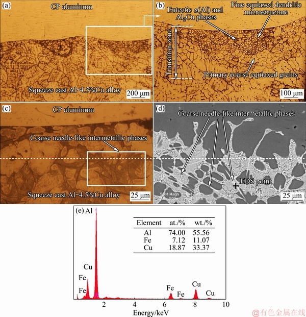
Fig. 14 Optical micrographs of patterned bimetal at interface region (a, b), coarse needle-like intermetallic compounds at high eutectic content areas of transition zone of patterned bimetal (c), SEM micrograph (d) and corresponding EDS analysis (e) of marked point
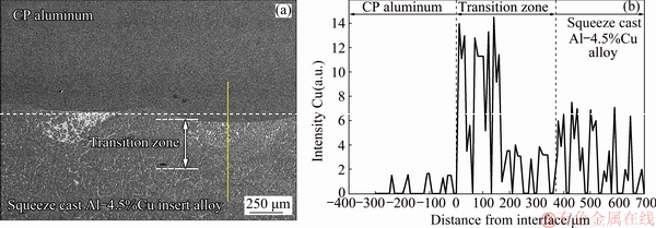
Fig. 15 SEM micrograph (a) and EDS analysis along shown-line across interface (b) of patterned bimetal
Formation of an interfacial transition zone in this case points to negligible effect of the surface oxide layer on heat transfer during manufacturing of the patterned bimetal. It is believed that the surface pattern machined on the insert top surface may have resulted in rupturing of the oxide layer during compound casting leading to the obvious microstructural changes. This will be discussed in more details in Section 3.3.
Higher magnification optical micrograph of the transition zone of the patterned bimetal is shown in Fig. 14(c). Higher copper concentration in this region (Fig. 15) has evidently resulted in higher content of the eutectic phases in the transition zone. Formation of some coarse needle-like phases within the eutectic structure of the transition zone is also evident in Fig. 14(c). However, microstructural observations showed no clear evidence of formation of these phases within the as squeeze cast microstructure of the Al-4.5wt.%Cu insert alloy (Fig. 12). As it was shown previously, the average non-equilibrium cooling rate during squeeze casting of the insert alloy was predicted to be about 14 ��C/s [21]. According to CULLITON et al [42], precipitation and growth of those intermetallic phases depend on the solid solubility of alloying elements in the ��(Al) matrix phase. Formation of such intermetallic phases requires sufficient time which does not seem to have been available during solidification of the insert alloy. This has inhibited precipitation and growth of the coarse needle-like intermetallic phases in the microstructure of as squeeze cast insert alloy.
SEM micrograph and EDS analysis of this phase are presented in Figs. 14(d, e). Based on the mole fraction of the main elements, i.e. Al, Cu and Fe, these needle-like phases could be associated with Al7Cu2Fe which is the closest stoichiometric formula of an available ternary intermetallic compound. According to the literature, formation of needle-like Al7Cu2Fe intermetallic precipitates with typical length of 0.7-2.7 ��m and hardness of 9.39 GPa is very likely during solidification of Al-Cu alloys [42].
It is noteworthy that appearance of random shrinkage porosities and such large needle-like intermetallic compounds along the interface region of the patterned bimetal could act as stress risers and, as a result, may weaken the interface and reduce the mechanical properties of the manufactured bimetal.
Good agreement of the simulation and experimental results of the patterned bimetal, when the effects of interfacial oxide layer was neglected in the simulations, raises the question of how the machined surface pattern would affect the thin interfacial oxide layer during the manufacturing process. It is believed that stability of such oxide layer depends on magnitude and distribution of the stresses generated along the interface during manufacturing. To assess this hypothesis, thermal and mechanical interfacial stresses imposed on such an oxide layer were simulated using ANSYS R17.0 simulation software.
3.3 Simulation of stress generated at interface
It can be envisaged that during the compound squeeze casting process, the following thermal and mechanical stresses are generated along the interface region of the manufactured bimetals: (1) Thermal stresses caused by pouring the hot (800 ��C) molten CP aluminum on the top surface of a much less hot (350 ��C) solid insert; (2) Mechanical stresses due to subsequent squeezing of the molten CP aluminum under a given applied pressure (70 MPa); (3) Internal stresses due to contraction of solidifying CP aluminum component and expansion of heating up squeeze cast Al-4.5wt.%Cu insert alloy; (4) High temperature phase transformations in the oxide layer during the manufacturing process.
It has been shown that aluminum oxide layer formed at room temperature is amorphous and its thickness increases with temperature. Continued growth of the amorphous oxide layer can be accompanied by its crystallization to ��-Al2O3, ��-Al2O3, ��-Al2O3 and ��-Al2O3 phases, which have lower specific volumes compared to the initial amorphous oxide layer [43]. These transformations may render some interfacial stresses on the oxide layer. In the compound casting process, as the molten metal is poured on the insert top surface, temperature of the amorphous oxide layer rises encouraging crystallization of the oxide layer. However, such transformation requires an incubation time at high temperature which does not seem to be provided in the manufacturing process of the bimetals. Accordingly, the effect of high temperature phase transformations of the surface oxide layer during the manufacturing process was ignored in this simulation.
von Mises yield criterion is formulated in terms of equivalent von Mises stress, ��v, based on Eq. (2) [44], where each stress component has two subscripts. The first subscript identifies the plane on which the stress acts and the second one denotes the direction on that plane.

 (2)
(2)
In case of two dimensional stress conditions, where ��xx, ��zz, ��xz and ��yz stress components are zero, the general equation can be summarized to Eq. (3) [44]. In this equation, ��yy and ��xy stress components are considered parallel to Y axis and XY plane, respectively.
 (3)
(3)
ANSYS simulation results for the extent and distribution of the equivalent von Mises stresses along the interface region of the flat bimetal were presented elsewhere [21]. These results demonstrated the formation of a homogeneous total equivalent von Mises compressive stress of 406 MPa along the interface of the flat bimetal which was considerably lower than the compressive strength of high purity Al2O3 (2660 MPa [45]). This revealed the stability of the interfacial oxide layer between the two components of the flat bimetal during the manufacturing process [21].
ANSYS simulation results for the extent and distribution of the equivalent von Mises stresses along the interface region of the patterned bimetal are shown in Fig. 16. This figure shows that stress distribution along the interface region is highly heterogeneous. Tips of the machined grooves experience a total thermal and mechanical stress of about 274 MPa in the normal direction. The roots experience a total stress of about 618 MPa and other locations are subjected to normal stresses of less than this value. Evidently, the developed compressive stress at any point of the interface is much less than the compressive strength of the oxide layer (about 2660 MPa [45]).
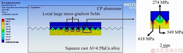
Fig. 16 Local large stress gradient fields along interface region of patterned bimetal simulated using ANSYS software
However, it is evident that the concentric groove pattern machined on the insert top surface can lead to formation of locally large stress gradient fields at the interface. The stress gradient developed between the tip and root of any groove is larger than 240 MPa/mm. Figure 17 schematically demonstrates how the total normal stress induced by interactions of the applied pressure and the internal stresses can be translated into two shear stress components at the tips of the surface machining pattern. This would lead to aggregation of an equivalent von Mises stress of 618 MPa at the roots of the grooves along the interfacial oxide layer which is about twice larger than the shear strength of Al2O3 (330 MPa [46]). It can be concluded, therefore, that shear stresses and local large stress gradient fields developed during manufacturing process at the interface of the insert of the patterned bimetal, are very likely to break up its interfacial thermal barrier oxide layer. As a result, machining such a simple concentric pattern on the insert top surface is expected to facilitate the heat transfer across the bimetal interface which leads to formation of a transition zone and better diffusion bonding along the interface region of the bimetal. ANSYS predictions are supported by the microstructural evidences presented in Section 3.2 for the patterned bimetal.
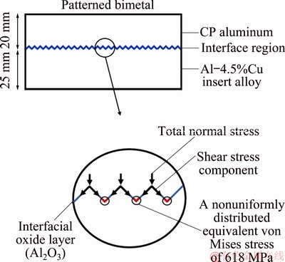
Fig. 17 Schematics of distribution of equivalent von Mises stress along interface region of patterned bimetal
3.4 Mechanical properties
3.4.1 Microhardness
Variations of microhardness across the interfaces of the patterned bimetal are shown in Fig. 18. Microhardness profile across the interfaces of the flat bimetal [21] is also shown in the figure for comparison. As it is seen from the figure, for the flat bimetal, the microhardness profile is rather flat in both the CP aluminum and the solid insert parts but changes abruptly at the interface. Microhardness values in the CP aluminum part and the squeeze cast Al-4.5wt.%Cu insert alloy range from about HV 24 to HV 29 and about HV 50 to HV 65, respectively. It is noteworthy that the microhardness profile corresponds well with the copper profile across the interface region of the flat bimetal [21].
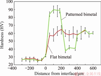
Fig. 18 Microhardness profiles across interface regions of manufactured bimetals
In the patterned bimetal, a much sharper increase followed by a steep decrease in the microhardness values across the interface is evident from Fig. 18 before it reaches a moderate value corresponding to microhardness of the insert. Variations in the microhardness values are in good agreement with EDS analysis of copper content across the interface region (Fig. 15). The maximum microhardness of the patterned bimetal (about HV 80-90) corresponds to the fine equiaxed dendritic microstructures with high interdendritic eutectic content and the minimum microhardness (about HV 38-45) corresponds to the primary coarse grains. It is clear that microhardness values are influenced by the presence of hard needle-like intermetallic Al7Cu2Fe precipitates (hardness value of 9.39 GPa [42]) as well as local grain size and copper content of different zones of the interface region.
3.4.2 Tensile properties
Macrographs of typical fractured tensile test specimens are shown in Fig. 19. The fact that fracture has occurred along the interface regions of both bimetals suggests that interface strength of the manufactured bimetals was lower than that of each of the bimetal parts. Therefore, it is clear that tensile strength of the manufactured bimetals is controlled by their interface strength.
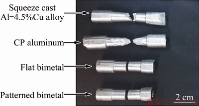
Fig. 19 Macrographs of fractured tensile test specimens
Typical stress-strain curves of tensile specimens taken from the specified regions of the bimetals (Fig. 8) are shown in Fig. 20(a). The 0-2% strain parts of the curves have been reproduced for more clarity. Average tensile properties of the samples are shown in Figs. 20(b-d). These figures reveal that all tensile properties of the bimetal are lower than those of the CP aluminum and the insert parts. Furthermore, it shows that all tensile properties of the flat bimetal are very poor. The average tensile strength and elongation at fracture for the flat bimetal are equal to 17 MPa and 0.6%, respectively, which are considerably lower than those of the CP aluminum and Al-4.5wt.%Cu insert alloy.
The average tensile strength and elongation at fracture of the patterned bimetal are about 54 MPa and 11.7%, respectively. In fact, the average tensile strength, yield strength and elongation of the patterned bimetal are about 68%, 52% and 94% higher than those of the flat bimetal, respectively.
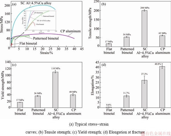
Fig. 20 Tensile properties of squeeze cast Al-4.5%Cu insert alloy, CP aluminum and manufactured bimetals
It is believed that the response of the interfacial surface oxide layer during compound squeeze casting plays a pivotal role in evolution of the differences in microstructure, copper distribution at the interface regions and the mechanical properties. As already described, the alumina oxide layer formed on the top surface of the solid insert is continuous and stable. It has a melting point of about 2000 ��C and has low wetting tendency with molten aluminum alloys [4,9-13]. It is postulated that this thermally stable oxide layer sitting between the solid insert and the solidifying CP aluminum melt does not evolve during the manufacturing process of the flat bimetal. Also the equivalent thermal and mechanical stresses generated along the interface region of the flat bimetal during the compound squeeze casting process are not large or inhomogeneous enough to interrupt this continuous oxide layer [21]. As a consequence, this interfacial oxide layer reduces the heat transfer and diffusion of atoms along the interface and prevents micromixing of the two melts if the surface of the insert alloy reaches its melting point. That is the reason for formation of a very weak bond between the two parts of the flat bimetal.
On the other hand, it was shown that the equivalent thermal and mechanical stresses generated at the interface region of the patterned bimetal during the compound squeeze casting process are larger and very heterogeneous leading to formation of locally concentrated stress zones at the interface region of the bimetal. This is believed to interrupt the continuous surface oxide layer during the compound squeeze casting process allowing for a direct metal-metal contact and improved heat transfer, diffusion and metallurgical bonding along the interface. In addition, discontinuous transition zones enjoying fine equiaxed grains with high interdendritic eutectic content areas may act as local strengthening sites along the interface region of the patterned bimetal. Strength is increased through the Hall-Petch and Orowan strengthening mechanisms which result in dislocation pile-up behind the intergranular regions of the transition zones. At the same time, formation of shrinkage porosities and coarse needle-like intermetallic compounds could adversely affect the tensile properties of the bimetal and weaken its interface.
It is noteworthy that the findings of this work present a low cost industrially viable approach to overcome the bonding problems caused by the stable oxide layer existing between the two parts of Al-Al compound squeeze cast bimetals. All previous efforts have made use of extensive chemical and coating treatments to get rid of this problem [14-20]. Chemical treatments are not very successful because the oxide layer will form very rapidly after the treatment. The coating treatments are also generally costly. The novelty of the proposed surface patterning is that no prior chemical or coating treatments on the insert top surface is required. In fact, the detrimental oxide layer is dealt with during the first few seconds of the manufacturing process under a molten liquid blanket where its restoration will no longer be possible.
4 Conclusions
(1) Machining a simple concentric groove pattern on the insert top surface significantly improved the microstructural features of the interface and the mechanical properties of the compound squeeze cast bimetal.
(2) ProCAST simulation results predicted complete surface melting along the interface region when the concentric groove pattern was machined on the insert top surface. Formation of an evident transition zone with average thickness of about 375 ��m between the two parts of the bimetal as well as micromixing and diffusion of copper atoms across the interface of the bimetal confirmed the simulation results.
(3) The transition zone of the bimetal was comprised mainly of primary coarse grains followed by fine equiaxed dendritic microstructures with high interdendritic eutectic content areas which strengthened the interface region of the bimetal. However, shrinkage porosities and hard needle-like intermetallic compounds formed at the transition zones could act as stress risers and interface weakening parameters.
(4) ANSYS simulation of thermal and mechanical stresses generated along the interface of the patterned bimetal indicated the formation of local large stress gradient fields along the interface leading to interruption of the interfacial oxide layer during the manufacturing process.
(5) Average tensile strength, yield strength and elongation of the patterned bimetal were about 68%, 52% and 94% higher than those of the flat bimetal, respectively.
(6) The novel approach suggested in this study is a cost-effective and promising method for manufacturing compound squeeze cast Al-Al macrocomposite bimetals without resort to any prior chemical or coating treatments of the solid insert.
Acknowledgements
The authors would like to acknowledge the financial support from Iran National Science Foundation (INSF) under grant number 95822903 and appreciate Mr. M. Lashani Zand for his help with ProCAST simulation software.
References
[1] Avner S H. Introduction to physical metallurgy [M]. 2nd ed. USA: McGraw-Hill, 1988.
[2] AlIZADEH A, EsLAMI M, BABAEE M H. Investigation on microstructure, mechanical properties and fracture mechanism of trimodal SiC reinforced Al5083/Al2024 aluminum alloy based nanocomposites fabricated by mechanical milling and hot extrusion processes [J]. Transactions of the Indian Institute of Metals, 2018, 71: 2325-2338.
[3] Chi Y, Gu G, Yu H, Chen C. Laser surface alloying on aluminum and its alloys: A review [J]. Optics and Lasers in Engineering, 2018, 100: 23-37.
[4] Tayal R K, Singh V, Kumar S, Garg R. Compound casting��A literature review[C]// Proc trends and advances in mechanical engineering. Faridabad, India: YMCA University of Science and Technology, 2012: 501-510.
[5] Bitsche R D. Design and computational analysis of compound castings and other multi-material structures [D]. Denmark: Vienna University of Technology, 2009.
[6] Anifantis N K, Georgantzinos S K, Giannopoulos G I, Kakavas P A. Elastomer macrocomposites [J]. Advanced Structured Materials, 2013, 12: 11-68.
[7] Yan G Y, Mao F, Chen F, Wu W, Cao Z Q, Wang T M, Li T J. Characteristics evolution of 6009/7050 bimetal slab prepared by direct-chill casting process [J]. Transactions of Nonferrous Metals Society of China, 2016, 26: 895-904.
[8] Bykov A A. Bimetal production and applications [J]. Steel in Translation, 2011, 41: 778-786.
[9] Liu T, Wang Q D, Liu P, Sun J W, Yin X L, Wang Q G. Microstructure and mechanical properties of overcast aluminum joints [J]. Transactions of Nonferrous Metals Society of China, 2015, 25: 1064-1072.
[10] Klassen A, Rubner M, Ilg J, Rupitsch S J, Lerch R, Singer R F, Korner C. Influence of the fabrication process on the functionality of piezoceramic patch transducers embedded in aluminum die castings [J]. Smart Materials and Structures, 2012, 21: 1-11.
[11] Liu G, Wang Q, Liu T, Ye B, Jiang H, Ding W. Effect of T6 heat treatment of microstructure and mechanical property of 6101/A356 bimetal fabricated by squeeze casting [J]. Materials Science and Engineering A, 2017, 696: 208-215.
[12] Feng J, Ye B, Zuo L, Wang Q, Wang Q, Jiang H, Ding W. Bonding of aluminum alloys in compound casting [J]. Metallurgical and Materials Transactions A, 2017, 48: 4632-4644.
[13] Papis K J M, Loeffler J F, Uggowitzer P J. Light metal compound casting [J]. Science China Technological Sciences, 2009, 52: 46-51.
[14] Papis K J M, Hallstedt B, Loffler J F, Uggowitzer P J. Interface formation in aluminum-aluminum compound casting [J]. Acta Materialia, 2008, 56: 3036-3043.
[15] Rubner M, Gunzl M, Korner C, Singer R F. Aluminum-aluminum compound fabrication by high pressure die casting [J]. Materials Science and Engineering A, 2011, 528: 7024-7029.
[16] Koerner C, Schwankl M, Himmler D. Aluminum-aluminum compound castings by electroless deposited zinc layers [J]. Journal of Materials Processing Technology, 2014, 214: 1094-1101.
[17] Liu T, Wang Q, Sui Y, Wang Q, Ding W. An investigation in to aluminum-aluminum bimetal fabrication by squeeze casting [J]. Materials & Design, 2015, 68: 8-17.
[18] Liu T, Wang Q, Sui Y, Wang Q. Microstructure and mechanical properties of overcast 6101-6101 wrought Al alloy joint by squeeze casting [J]. Journal of Materials Science and Technology, 2016, 32: 298-304.
[19] Schwankl M, Wedler J, Korner C. Wrought Al-cast Al compound casting based on zincate treatment for aluminum wrought alloy inserts [J]. Journal of Materials Science and Technology, 2016, 238: 160-168.
[20] Feng B, Xin Y, Sun Z, Yu H, Wang J, Liu Q. On the rule of mixtures for bimetal composites [J]. Materials Science and Engineering A, 2017, 704: 173-180.
[21] BABAEE M H , NIROUMAND B, MALEKI A, LASHANI ZAND M. Simulation and experimental verification of interfacial interactions in a compound squeeze cast Al/Al-Cu macrocomposite bimetal [J]. Transactions of Nonferrous Metals Society of China, 2019, 29: 950-963.
[22] Hufnagel W. Key to aluminuim alloys: designations, compositions, trade names of aluminuim materials [M]. USA: Aluminum-Verlag, 1982.
[23] Pantelakis S G, Chamos A N, Kermanidis A T. A critical consideration for the use of Al-cladding for protecting aircraft aluminum alloy 2024 against corrosion [J]. Theoretical and Applied Fracture Mechanics, 2012, 57: 36-42.
[24] Sun S, Zheng Q, Li D, Wen J. Long-term atmospheric corrosion behavior of aluminum alloys 2024 and 7075 in urban, coastal and industrial environments [J]. Corrosion Science, 2009, 51: 719-727.
[25] Petroyiannis P V, Pantelakis S G, Haidemenopoulos G N. Protective roll of local Al cladding against corrosion damage and hydrogen embrittlement of 2024 aluminum alloy specimens [J]. Theoretical and Applied Fracture Mechanics, 2005, 44: 70-81.
[26] Kutz M. Handbook of materials selection [M]. 1st ed. USA: Wiley, 2002.
[27] Mathers G. The welding of aluminuim and its alloys [M]. 1st ed. Amsterdam: Elsevier, 2002.
[28] Maleki A, Shafyei A, Niroumand B. Effects of squeeze casting parameters on the microstructure of LM13 alloy [J]. Journal of Materials Processing Technology, 2009, 209: 3790-3797.
[29] Maleki A, Niroumand B, Shafyei A. Effects of squeeze casting parameters on density, macrostructure and hardness of LM13 alloy [J]. Materials Science and Engineering A, 2006, 428: 135-140.
[30] Khodaverdizadeh H, Niroumand B. Effects of applied pressure on microstructure and mechanical properties of squeeze cast ductile iron [J]. Materials & Design, 2011, 32: 4747-4755.
[31] Baghi M, Niroumand B, Emadi R. Fabrication and characterization of squeeze cast A413-CSF composites [J]. Journal of Alloys and Compounds, 2017, 710: 29-36.
[32] Seiyed Beigi M T, Niroumand B. Liquid segregation behavior of a semi-solid squeeze cast A356 aluminum cup-shaped part [J]. Journal of Materials Science and Technology, 2017, 33: 2203-2211.
[33] Pourmahmoudi H R, Niroumand B. Effect of pressure on graphite morphology and mechanical properties of squeeze cast hyper-eutectic grey cast iron [J]. Transactions of the Indian Institute of Metals, 2018, 71: 1401-1410.
[34] Chadwick G A, Yue T M. Principles and applications of squeeze castings [J]. Metals and Materials International, 1989, 5: 6-12.
[35] Ho K, Pehlke R D. Metal-mold interfacial heat transfer [J]. Metallurgical and Materials Transactions B, 1985, 16: 585-594.
[36] Fardi Ilkhchy A, Jabbari M, Davami P. Effect of pressure on heat transfer coefficient at the metal/mold interface of A356 aluminum alloy [J]. International Communications in Heat and Mass Transfer, 2012, 39: 705-712.
[37] Nishida Y, Matsubara H. Effect of pressure on heat transfer at the metal-mold casting interface [J]. The British Foundryman, 1976, 69: 274-278.
[38] ESI Group. ProCAST User��s Manual [M]. The Virtual Try Out Space Company, 2016.
[39] Naterer G F. Heat transfer in single and multiphase systems [M]. 1st ed. USA: CRC Press, 2002.
[40] ASTM Standard-E407. Standard practice for microetching metals and alloys [S]. 2007.
[41] Zhang M, Zhang W, Zhao H, Zhang D, Li Y. Effect of pressure on microstructures and mechanical properties of Al-Cu- based alloy prepared by squeeze casting [J]. Transactions of Nonferrous Metals Society of China, 2007, 17: 496-501.
[42] Culliton D, Betts A J, Kennedy D. Impact of intermetallic precipitates on the tribological and/or corrosion performance of cast aluminum alloys: A short review [J]. International Journal of Cast Metals Research, 2013, 26: 65-71.
[43] Trunov M A, Schoenitz M, Dreizin E L. Effect of polymorphic phase transformations in alumina layer on ignition of aluminum particles [J]. Combustion Theory and Modeling, 2006, 10: 603-623.
[44] HILL R. The Mathematical theory of plasticity [M]. 2nd ed. UK: Oxford University Press, 1998.
[45] ASTM Standard-D2442. Standard specification for Alumina ceramics for electrical and electronic applications [S]. 2016.
[46] Thermal and structural properties of fusion related materials [EB/OL]. http://www-ferp.ucsd.edu/LIB/PROPS/PANOS.
��߸��ϼ�ѹ����Al/Al-Cu˫������۸��ϲ��Ͻ����ϵ��·���
Mohammad Hossein BABAEE1, Ali MALEKI2, Behzad NIROUMAND1
1. Department of Materials Engineering, Isfahan University of Technology, Isfahan 84156-83111, Iran;
2. Department of Mechanical Engineering, Isfahan University of Technology, Isfahan 84156-83111, Iran
ժ Ҫ������һ�ּ�����߸��ϼ�ѹ����Al/Al-4.5wt.%Cu ˫�������ϲ��Ͻ����ϵ��·��������о��÷����Դ�˫����������֯����ѧ���ܵ�Ӱ�졣�ڼ�ѹ����Al-4.5wt.%Cu���ڱ�����ӹ�һ�������ͬ�IJ�ͼ��������ProCAST��ANSYS������˫����������������Ĵ��ȡ����̺Ͳ�����Ӧ���ֲ�������ֵģ�⣬������ʵ����֤��ģ�������������湵�ۼ����ȫ�ۻ����ؽ�������ϴ�ľֲ�Ӧ���ݶȳ�����ᵼ�²������������������ѣ��ٽ�˫������ֵ���ɢ��ϡ�����֯����֤ʵ˫��������������ԵĹ�������ͨ���ӹ�����ͼ����˫������ƽ����������ȺͿ���ǿ�ȷֱ��������ӵ�375 ��m ��54 MPa����ˣ��÷�����һ�־��ÿ��еĸ��ϼ�ѹ������-����۸���˫�����ķ���������Ҫ��ǰ�Թ����������κγɱ���ʱ���ܼ��͵Ļ�ѧ��Ϳ�㴦����
�ؼ��ʣ�Al/Al-4.5wt.%Cu ��۸���˫�����������ϣ�������ӹ�ͼ��������֯����ѧ���ܣ�ģ��
(Edited by Xiang-qun LI)
Corresponding author: Behzad NIROUMAND; Tel: +98-31-33915731; Fax: +98-31-33912752; E-mail: behzn@cc.iut.ac.ir
DOI: 10.1016/S1003-6326(19)65026-0
Abstract: A facile and innovative method to improve bonding between the two parts of compound squeeze cast Al/Al-4.5wt.%Cu macrocomposite bimetals was developed and its effects on microstructure and mechanical properties of the bimetal were investigated. A special concentric groove pattern was machined on the top surface of the insert (squeeze cast Al-4.5wt.%Cu) and its effects on heat transfer, solidification and distribution of generated stresses along the interface region of the bimetal components were simulated using ProCAST and ANSYS softwares and experimentally verified. Simulation results indicated complete melting of the tips of the surface grooves and local generation of large stress gradient fields along the interface. These are believed to result in rupture of the insert interfacial aluminum oxide layer facilitating diffusion bonding of the bimetal components. Microstructural evaluations confirmed formation of an evident transition zone along the interface region of the bimetal. Average thickness of the transition zone and tensile strength of the bimetal were significantly increased to about 375 ��m and 54 MPa, respectively, by applying the surface pattern. The proposed method is an affordable and promising approach for compound squeeze casting of Al-Al macrocomposite bimetals without resort to any prior cost and time intensive chemical or coating treatments of the solid insert.
[1] Avner S H. Introduction to physical metallurgy [M]. 2nd ed. USA: McGraw-Hill, 1988.
[8] Bykov A A. Bimetal production and applications [J]. Steel in Translation, 2011, 41: 778-786.
[26] Kutz M. Handbook of materials selection [M]. 1st ed. USA: Wiley, 2002.
[27] Mathers G. The welding of aluminuim and its alloys [M]. 1st ed. Amsterdam: Elsevier, 2002.
[38] ESI Group. ProCAST User��s Manual [M]. The Virtual Try Out Space Company, 2016.
[39] Naterer G F. Heat transfer in single and multiphase systems [M]. 1st ed. USA: CRC Press, 2002.
[40] ASTM Standard-E407. Standard practice for microetching metals and alloys [S]. 2007.
[44] HILL R. The Mathematical theory of plasticity [M]. 2nd ed. UK: Oxford University Press, 1998.
