

J. Cent. South Univ. (2020) 27: 2324-2337
DOI: https://doi.org/10.1007/s11771-020-4452-5

Heat transfer simulation of annular elliptical fin-and-tube heat exchanger by transition SST model
H NEMATI1, A R RAHIMZADEH2, WANG Chi-chuan3
1. Department of Mechanics, Marvdasht Branch, Islamic Azad University, Marvdasht, Iran;
2. Mechanical Engineering, Islamic Azad University, Bushehr branch, Bushehr, Iran;
3. Department of Mechanical Engineering, National Chiao Tung University, Hsinchu 300, Taiwan, China
 Central South University Press and Springer-Verlag GmbH Germany, part of Springer Nature 2020
Abstract:
In this study, thermo-fluid characteristics of elliptical annular finned tube heat exchanger were numerically studied in detail. Transition SST model was utilized to simulate turbulent flow. Effects of air velocities, horizontal to vertical fin diameter ratios, and fin densities were examined in detail. The simulations indicate superior performance of elliptical fin layout. It was shown that pressure drop of annular elliptical fin can be only one half of that of a circular annular fin while containing comparable heat transfer performance. The vertical elliptical annular fin may even contain a higher heat transfer performance over circular fin. Correlations are proposed to estimate the Nu number and pressure drop based on the annular circular fin. The maximum deviations between the proposed correlations and simulations regarding pressure drop and heat transfer coefficient are 5.6% and 3.2%, respectively. For further elaboration of the superiority of the elliptical layout from the second law perspective, normalized entropy generation was also studied. In all cases, the entropy generation rate in circular fin was higher than that of an elliptical fin.
Key words:
annular fin; elliptical fin; entropy generation; transition SST model; tube bundle��
Cite this article as:
H NEMATI, A R RAHIMZADEH, WANG Chi-chuan. Heat transfer simulation of annular elliptical fin-and-tube heat exchanger by transition SST model [J]. Journal of Central South University, 2020, 27(8): 2324-2337.
DOI:https://dx.doi.org/https://doi.org/10.1007/s11771-020-4452-51 Introduction
Extended surface is used extensively to enhance heat transfer [1-3] and annular circular fin is a typical type of extended surfaces that is commonly used to augment heat transfer in air-cooled heat exchangers [4]. This type of fin is studied comprehensively both experimentally and numerically [5-14]. JANG et al [15] were the first people who worked numerically on annular finned tube bundle. They used both numerical and experimental methods to study heat transfer and fluid flow in a four-row annular circular finned tube heat exchanger. They assumed that the flow regime is laminar. Later, MON et al [16] extended the modelling to turbulent fluid flow regime. The effects of fin spacing, arrangements (in-line or staggered) of the annular fins having four-row configuration were reported. NEMATI et al [17] studied different methods of turbulent flow modelling over a four-row annular finned tube and complex phenomena such as flow separation, horseshoe vortices, generated wakes were well elaborated. Good agreements had been reported against experimental correlations.
Though the annular circular fins are widely used in practice, the fin geometry and layout is not optimized yet. Figure 1 shows a typical temperature distribution over a circular annular fin.
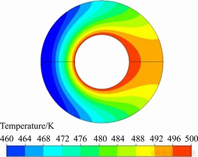
Figure 1 Typical temperature distribution over annular circular fin [30]
This figure proves that the local heat transfer coefficient varies considerably over the fin area. It is much higher in fin windward relative to the lateral or rear side. This non-uniformity in heat transfer causes non-uniform temperature distribution. Upon the non-uniformity in temperature distribution, leaving appreciable spaces for further improvements and one of the possible resolutions is to change the geometry from axis-symmetric to asymmetric.
Several modifications in fin geometry had been proposed. For example, BOSNJAKOVIC et al [18] proposed a needle-type annular fin. MORALES-FUENTES et al [19] compared a circular annular fin with a pin fin numerically. However, they did not report complete superiority among them. Each fin design reveals its own advantages and disadvantages. Circular fin with eccentricity relative to the tube center had also been proposed [20, 21]. However, manufacturing an eccentric fin may not be as easy as a concentric one.
Another option is the annular elliptical fin. At first glance, annular elliptical fins can be a good choice for various situations [22]. This is because the weight or restricted space plays a pivotal role, and the design shows the inherited benefits from such perspective. Figure 2 shows a typical annular elliptical finned tube. Although the elliptical tubes had been studied widely [23-27], there was no in-depth analysis regarding annular elliptical fins. KUNDU et al [28] used a semi-analytical method to determine elliptical fin efficiency. Their analytical work was in terms of a series of Bessel function family. Based on a large set of numerical simulations, NEMATI et al [29] proposed a generalized correlation to predict circular and elliptical fin efficiency. Yet they further numerically modeled a one-row elliptical fin [30], delineating that pressure drop over an elliptical fin is smaller than that over a circular fin. Despite its superior performance, there was no available predictive correlation for the geometry, thereby placing a roadblock for industrial applications.
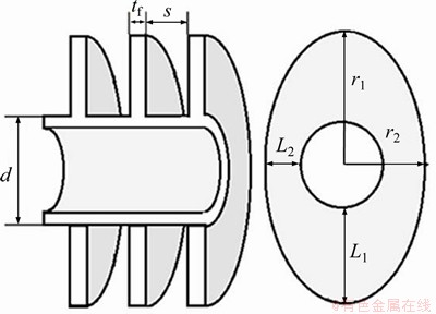
Figure 2 Typical annular elliptical finned tube
In this regard, the objective of this study is to fill the gap between academic analyzing and industrial applications for this fin layout. Firstly, thermal and hydraulic characteristics of elliptical annular fins are thoroughly studied numerically and compared with circular fins. Secondly, with wide ranges of velocity and diameter ratio via simulations relevant correlations are proposed, which can assist the engineers in the quick estimation of the average heat transfer and pressure drop from the circular fins.
2 Numerical simulation detail
Figure 3 shows the schematic domain for the conservation equations. The radius parallel to fluid stream has been named rh and radius at the right angle to fluid stream is termed rv. As a result, rh/rv<1 indicates vertical ellipse, while rh/rv>1 indicates horizontal ellipse. Dotted lines in Figure 3 show symmetry boundaries. Boundaries have been extended 2.4 times and 7.2 times the larger fin radius from the center of the tube in upside and downside, respectively. These distances are far enough not to affect solution results.
2.1 Governing equations
The critical Reynolds for annular fins is Re=105 [31]. However, even in this high Reynolds number; both laminar and turbulent flow may be observed in an annular finned tube bundle [32]. In this regard, the transition SST model was utilized to simulate turbulent flow. In the transition SST model, two other transport equations are coupled to the SST K-�� transport equations. One of them can predict the intermittency while the other, can forecast the onset transition criteria in terms of momentum-thickness Reynolds number. Because of these two extra transport equations, both laminar and turbulent flows, as well as their transition, may be simulated [33]. The governing equations are:

Figure 3 Schematic domain for conservation equations:
Continuity equation for the fluid zone:
 (1)
(1)
Momentum equation for the fluid zone:
 i, j=1, 2, 3 (2)
Energy equation for the fluid zone:
 (3)
(3)
where E is the total energy; keff=k+kt is effective thermal conductivity.
Energy equation in the solid zone:
 (4)
(4)
In Eqs. (2) and (3), ��t and kt are turbulent viscosity and turbulent thermal conductivity, respectively, and are equal to zero in laminar flow. The turbulent flow is simulated using the transition SST model as specified in Eqs. (5) and (6):
 (5)
(5)

 (6)
(6)
The results of these two equations are turbulent kinetic energy, ��, and the specific rate of turbulence dissipation, ��. Correspondingly, ��t can be evaluated as:
 (7)
(7)
where S is the magnitude of strain rate; F1 and F2 are blending functions in SST mode and limit the eddy viscosity inside the boundary layer thickness.
Two other transport equations are coupled with Eqs. (5) and (6): one of them for the intermittency and the other for the transition onset criteria. Equation (8) is used to determine the damping function, ��, specified in Eq. (5). This factor which multiplies the production term Pk, does not exist in the standard SST model and is used to diminish the rate of turbulence production in the non-fully turbulent flow. Its value is between 0 and 1. However, �� is a function of a new parameter, ��, which shows the local stability of the flow in the region near the wall.

 (8)
(8)
 (9)
(9)
The terms P and E in Eqs. (8) and (9) refer to the production and destruction of the dependent variables. The foregoing equations can predict the transition from turbulent to the laminar regime and vice versa. For more details, one can refer to Ref. [34].
2.2 Boundary conditions
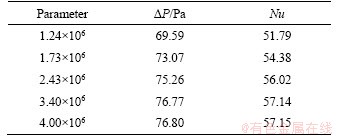
Dry air flows through the bundle with the normal velocity Uin with inlet temperature Tin= 308.15 K, the turbulent intensity I=1% [17]. Uin varies from 1.5 to 3 m/s. The fin and tube are made from aluminum, and the tube has a constant temperature, Tw=283.15 K. Temperature gradient normal to symmetry plane is zero. It is also true for the normal component of velocity at the symmetry plane. A very fine mesh is used to discretize the domain. Grids near the fin peripheral are even finer. Figure 4 shows a typical sample of the generated mesh. The mesh is further refined to ensure y+<2 [35]. Therefore, several mesh rows are located in viscous sublayer which is widely spanned in 0<>+<5. Mesh study is also performed to ensure the independence of solution from grid number. The grid-independent study was carried out for a fin density of 11 fins/in. at Re=104. The results are presented in Table 1.

Figure 4 Typical mesh for horizontal annular elliptical fin
Table 1 Mesh study results for the fin density of 11 fins/in at Re=104
Results were obtained by solving the steady-state turbulent fluid flow inside the fluid domain using the Fluent solver module, ANSYS 18.0. Semi-implicit method for pressure-linked equations (SIMPLE) algorithm was utilized to solve the pressure-velocity coupling. The second-order method was selected to discretize energy and pressure equations. The momentum conservation equation was also discretized by the second-order upwind scheme. Moreover, Eqs. (8) and (9) were discretized by the first-order method. The maximum acceptable residuals for continuity and velocities were set to 10-5 while the value for the energy conservation equation was set to 10-6. Furthermore, mass-weighted averages of the pressure drop as well as outlet temperature were monitored in every two iterations, to ensure the convergence of the simulation.
3 Data analysis
Selected geometries for the circular finned tube are shown in Table 2. They are commonly used in air-cooled heat exchangers [36]. The annular elliptical fins have been assumed to be surrounded inside the circular fins (Figure 5). By this assumption, the larger diameters of all ellipse are equal to circular fin diameter, i.e. 57.15 mm.
Table 2 Circular finned tube geometry
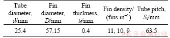
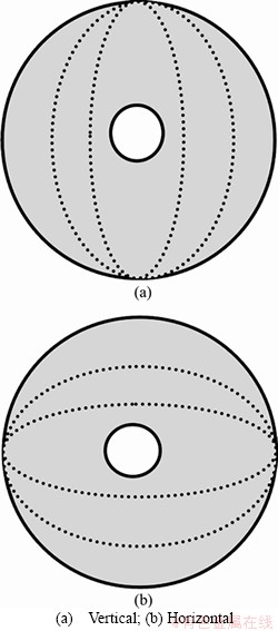
Figure 5 Elliptical fins geometry:
The ratio rh/rv varies from 0.8 to 1.25. It is clear that a special case of an elliptical fin is the circular fin of which both horizontal and vertical diameters are both the same, i.e. rh/rv=1.
The total heat exchange between the air and the fin, , is:
, is:
 (10)
(10)
where is the total enthalpy. The average convective heat transfer coefficient is defined as:
 (11)
(11)
where Af is fin area; A is total heat transfer area; �� is log mean temperature difference.
 (12)
(12)
where Tin is the average inlet temperature; Tout is the average outlet temperature; Tw is tube surface temperature. The fin efficiency, ��, can be estimated by [29]:
 (13)
(13)
 (14)
(14)
where kf is the thermal conductivity of the fin; tf is the fin thickness and the tube outer diameter is d. The average fin length,  , and the average fin radius,
 , are defined as:
 (15)
(15)
 (16)
(16)
 (17)
(17)
4 Results and data discussion
4.1 Data validation
The simulations are first compared with the circular fin which represents a special kind of elliptical fins. The calculated results, in terms of average weighted pressure drop and Nusselt number, were compared with several experimental correlations:
 (18)
(18)
The following five experimental correlations are used for Nu comparison [37-40]:
 (19)
(19)
 (20)
(20)
 (21)
(21)
 (22)
(22)
 (23)
(23)
Also, the following four equations are used for pressure drop comparison [38, 39, 41]:
 (24)
(24)
 (25)
(25)
 (26)
(26)
 (27)
(27)
and also:
 (28)
(28)
Figure 6 shows the comparison of Nusselt number with those experimental correlations for three fin densities at different Reynolds numbers and different fin densities. As shown in Figure 6, numerical results show good agreements with most of the existing correlations.
The comparisons of ��P calculated by the numerical method and experimental correlations are also presented in Figure 7 for three different fin densities at different Reynolds numbers. Again, very good agreements are found between numerical results and experimental correlations. The foregoing comparisons substantiate the applicability of the present numerical simulation.
4.2 Numerical flow visualization
For further elaborations of the numerical examinations, some numerical results for an inlet velocity of 3 m/s are presented in the following.
Figure 8 shows pathlines over elliptical and circular annular fins. The generated vortex behind circular fins is longer than elliptical fins. Therefore, it is expected that pressure drop over elliptical fins is less than circular fins.
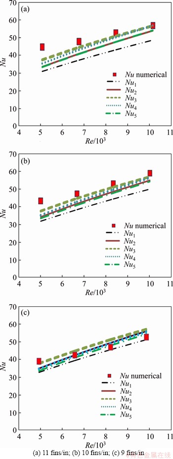
Figure 6 Nu number for circular fin at different Re number for:
The velocity vectors between fins in the first row are also shown in Figure 9. The existence of horseshoe vortexes is clearly seen in all those fins. Moreover, flow behavior is similar to a developing flow. By increasing the length of the channel, the flow approaches fully developed manner. This can explain well why by increasing the channel length from horizontal elliptical to circular fin and then to vertical elliptical fin (reducing the horizontal tube length) results in superior heat transfer performance.
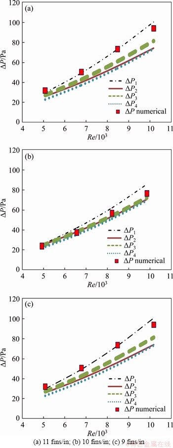
Figure 7 ��P for circular fin at different Re number for:
The velocity vector over the fins is also shown in Figure 10. As depicted in Figure 10, the separation of flow from the fin edge of vertical elliptical fins occurs at a smaller angle in comparison with circular fins. The separation over circular fins also occurs faster when compared with horizontal elliptical fins.
Temperature contours are also shown in Figure 11. According to this figure, for circular fins (rh/rv=1), the fluid temperature does not change significantly after the second row. However, in elliptical fins with rh/rv=0.8 or rh/rv=1.25, temperature variation is still considerable, thereby suggesting the higher heat transfer performance at rear rows. This result may be also explained from the temperature contours over fins, as shown in Figure 12. From Figure 12, vertical elliptical fins offer higher temperature primarily at the rear fins surface area, thereby issuing a higher heat transfer rate per unit of surface area.
4.3 Presented correlations
As far as engineering practice is concerned, reliable and accurate correlations are imperative. Hence, an appreciable amount of simulations are first conducted for the elliptical layout and the simulated cases pressure drops are normalized by circular fins pressure drops as shown in Figure 13. Scattering in data points is associated with variations in inlet velocity as well as fin density variations. Yet this ratio is relatively independent of fin density or inlet velocity and it can be assumed to be a function of diameter ratio only. For each fin diameter ratio, the deviations in data points relative to the average value are less than 5.6%. Note that the pressure drop across circular fin is higher than that of the vertical elliptical fin. Interestingly, the pressure drop over horizontal elliptical fins (diameter ratio more than unity) is less than circular fins for about 30%.
Analogously, the normalized Nu is shown in Figure 14. The normalized Nu also shows weak dependence on inlet velocity or fin density and it can be assumed as a function of diameter ratio only. For the Nu ratio, the maximum deviation in data points relative to the average values is less than 3.8%.
After some mathematical manipulations and iterations for minimizing the predictive errors, the following correlations are proposed to predict the Nu number and pressure drop based on the annular circular fin.
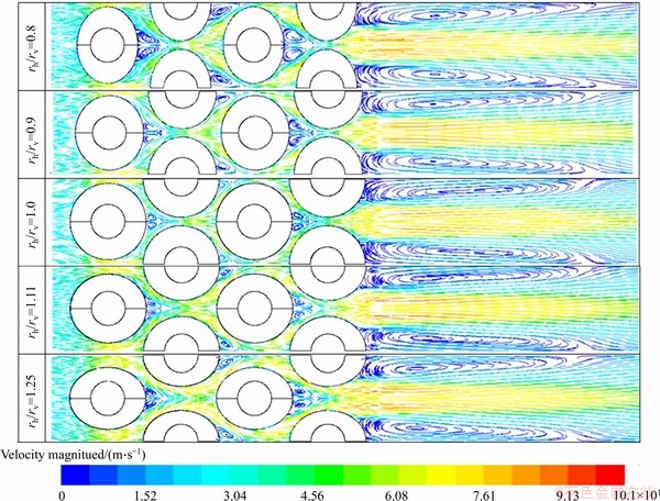
Figure 8 Fluid streamlines colored by velocity magnitude over tube bank with 11 fins/in
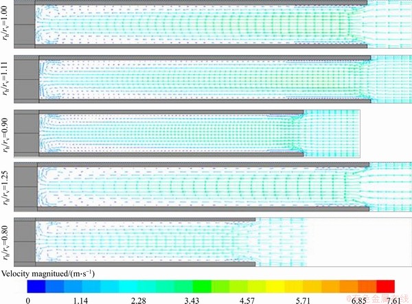
Figure 9 Velocity vectors between fins in first row of tube bank with 11 fins/in
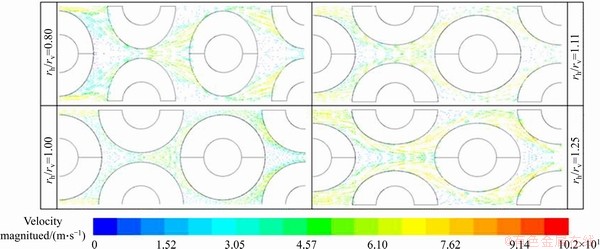
Figure 10 Velocity vectors over fins of tube bank with 11 fins/in
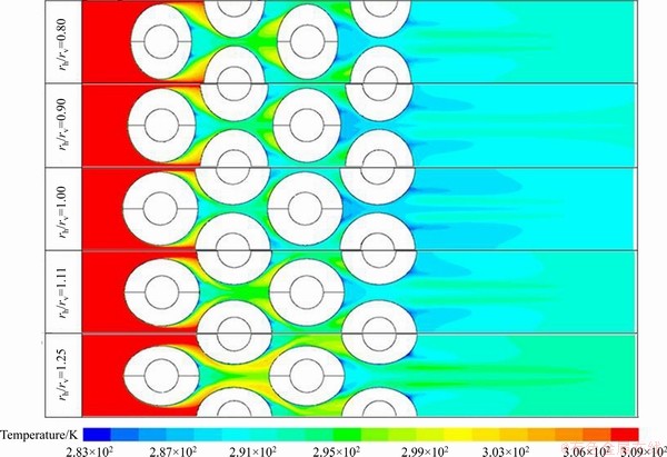
Figure 11 Temperature contours over fins of tube bank with 11 fins/in
 (29)
(29)
 (30)
(30)
where the subscripts ��c�� denotes circular fin. The standard error for both Eqs. (29) and (30) is less than 0.02. For  Eq. (29) reveals that
4.4 Elliptical and circular fin comparison
According to Figure 14, for a horizontal elliptical fin with high aspect ratio, Nu ratio may be low as much as 90%. However, the corresponding pressure drop, in this case, is as low as 70%. So, higher inlet velocity can be used to compensate for the heat transfer rate with the same pressure drop. To balance pressure drop and heat transfer, the entropy generation for each case is calculated in the following:
 (31)
(31)
and ��s is defined as:
 (32)
(32)
CP=1006.43 J/(kg��K) and R=287.16 J/(kg��K). Again, entropy generation in each case is normalized by dividing by entropy generation of the circular fin. The results are shown in Figure 15. Apparently, the entropy generation for circular fins peaks at the plateau when comparing with either rh/rv is above or less than unity. According to this figure in the elliptical fin, the entropy generation on average can be reduced by 20% when compared with a circular fin.
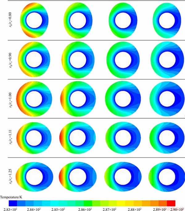
Figure 12 Temperature contours over fins of tube bank with 11 fins/in
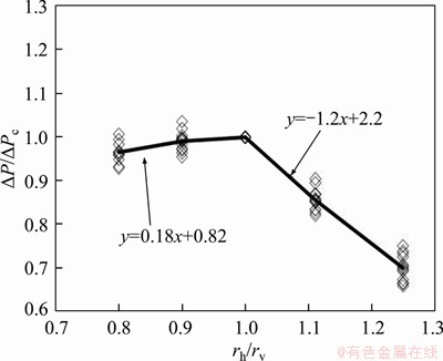
Figure 13 Normalized pressure drop for various inlet velocity or fin density
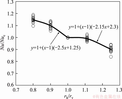
Figure 14 Normalized Nu for various inlet velocity or fin density
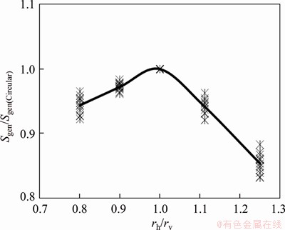
Figure 15 Normalized entropy generation
5 Conclusions
This study examined the thermo-fluid characteristics of annular elliptical finned tube heat exchanger having 4-row layout. Both vertical ellipse and horizontal ellipse of the elliptical layouts are studied in detail. Air at standard conditions is used for simulation. The corresponding inlet velocity varies from 1.5 to 3.0 m/s. Based on the foregoing simulations and comparisons, the following results are concluded.
1) Superiority in the performance of annular elliptical fin over circular type was found. This is concluded both the thermo-hydraulic performance and from the second law (entropy generation) perspective.
2) The pressure drop for the elliptical fin is smaller than the circular fin while containing a comparable heat transfer coefficient over circular fin. This phenomenon becomes even more pronounced when the vertical elliptical finned tube is used, which shows a superior heat transfer performance over circular fin.
3) Furthermore, based on the entropy generation calculation, it is found that the entropy generation for circular fin exceeds both vertical ellipse and horizontal ellipse layout.Although the horizontal elliptical layout contains a small reduction in Nusselt number. It can be compensated easily by its very low pressure drop.
4) Correlations applicable for the elliptical finned geometry, normalized with the pressure drop ratio or Nusselt number ratio against the circular fin are proposed. The maximum deviations between the proposed correlations and simulations regarding pressure drop and heat transfer coefficient are 5.6% and 3.2%, respectively.
Acknowledgments
The last author (Chi-chuan WANG) would like to acknowledge the financial support from Ministry of Science and Technology, Taiwan, China under contract No. 107-2221-E-009-143.
Nomenclature
A=Af+At
Fin tube heat transfer area per unit length of tube (m2)
A
Transition SST model constant
Af
Fin surface area per unit length of fin tube (m2)
Aff
Minimum free flow area of finned tube per unit length (m2)
At
Tube heat transfer area per unit length of fin tube (m2)
A��
Heat transfer area per unit length of finned tube (m2)
a
Transition SST model constant
d
Tube outer diameter (m)
Total enthalpy of airflow rate (W)
h
Average convective heat transfer coefficient (W/(m2��K))
hf
Fin height (mm)
k
Air thermal conductivity (W/(m��K))
kt
Turbulent thermal conductivity (W/(m��K))
L1
Larger fin length (m)
L2
Smaller fin length (m)
Nu=hd/k
Nusselt number
n
Number of tube rows
P
Pressure (Pa)
Heat transfer between fin-tube and air (W)
q
Heat transfer between fin-tube and air per unit air mass flow rate (J/kg)
rh
Horizontal fin radius (m)
rv
Vertical fin radius (m)
r1
Larger fin radius (m)
r2
Smaller fin radius (m)
S
Absolute value of the shear strain rate (s-1)
s
Fin spacing (m)
sgen
Entropy generation (J/(kg��K))
T
Average temperature (K)
Tw
Tube surface temperature (K)
tf
Fin thickness (m)
Uin
Air inlet velocity (m/s)
umax
Maximum average velocity inside the tube bundle (m/s)
��1, ��2
Transition SST model constants
��P
Tube bundle pressure drop (Pa)
��S
Entropy change (J/(kg��K))
��
Fin efficiency
��
Log mean temperature difference (K)
k
Turbulent kinetic energy (m2��s-2)
��
Viscosity (Pa��s)
��
Density of air (kg/m3)
��
Specific rate of turbulence dissipation (s-1)
��
Intermittency adjunct function
References
[1] NI M L, CHEN Y P, DONG C, WU J F. Numerical simulation of heat transfer and flow of cooling air in triangular wavy fin channels [J]. Journal of Central South University, 2014, 21(7): 2759-2765.
[2] GHASEMI S, VALIPOUR P, HATAMI M, GANJI D. Heat transfer study on solid and porous convective fins with temperature-dependent heat generation using efficient analytical method [J]. Journal of Central South University, 2014, 21(12): 4592-4598.
[3] MOSAYEBIDORCHEH S, RAHIMI-GORJI M, GANJI D, MOAYEBIDORCHEH T, POURMEHRAN O, BIGLARIAN M. Transient thermal behavior of radial fins of rectangular, triangular and hyperbolic profiles with temperature-dependent properties using DTM-FDM [J]. Journal of Central South University, 2017, 24(3): 675-682.
[4] SHAH R K, SEKULIC D P. Fundamentals of heat exchanger design [M]. John Wiley & Sons, 2003.
[5] NEAL S, HITCHCOCK J. A study of the heat transfer processes in banks of finned tubes in cross flow, using a large scale model technique [C]// Proceedings of the Third International Heat Transfer Conference. Chicago, Illinois, 1966.
[6] LEGKIY V. Investigation of local heat transfer in a tube with annular fins in transverse air flow [J]. Heat Tranfer-Soviet Research, 1974, 6: 101-107.
[7] STASIULEVICIUS J, SKRINSKA A, ZUKAUSKAS A. Heat transfer of finned tube bundles in crossflow [J]. International Journal of Heat and Fluid Flow, 1998, 9(3): 347-348.
[8] GOROBETS V. Coupled convective heat transfer from annular fins in transverse flow [J]. Journal Of Applied Mechanics And Technical Physics, 1993, 34: 392-398.
[9] XI G, TORIKOSHI K. Computation and visualization of flow and heat transfer in finned tube heat exchangers [C]// The 1996 4th International Symposium on Heat Transfer, ISHT, Beijing, China, 1996: 632-637.
[10] HASHIZUME K, MORIKAWA R, KOYAMA T, MATSUE T. Fin efficiency of serrated fins [J]. Heat Transfer Engineering, 2002, 23: 6-14.
[11] YAKAR G, KARABACAK R. Investigation of thermal performance of perforated finned heat exchangers [J]. Experimental Heat Transfer, 2015, 28: 354-365.
[12] BUYRUK E, KARABULUT K. Enhancement of heat transfer for plate fin heat exchangers considering the effects of fin arrangements [J]. Heat Transfer Engineering, 2018, 39: 1392-1404.
[13] VALIKANGAS T, KARVINEN R. Conjugated heat transfer simulation of a fin-and-tube heat exchanger [J]. Heat Transfer Engineering, 2018, 39: 1192-1200.
[14] NEMATI H, MORADAGHAY M. Parametric study of natural convection over horizontal annular finned tube [J]. Journal of Central South University, 2019, 26(8): 2077- 2087.
[15] JANG J Y, LAI J T, LIU L C. The thermal-hydraulic characteristics of staggered circular finned-tube heat exchangers under dry and dehumidifying conditions [J]. Int J Heat Mass Tran, 1998, 41: 3321-3337.
[16] MON M S, GROSS U. Numerical study of fin-spacing effects in annular-finned tube heat exchangers [J]. Int J Heat Mass Tran, 2004, 47: 1953-1964.
[17] NEMATI H, MOGHIMI M. Numerical study of flow over annular-finned tube heat exchangers by different turbulent models [J]. CFD Letters, 2014, 6: 101-112.
[18] BOSNJAKOVIC M, CIKIC A, MUHIC S, STOJKOV M. Development of a new type of finned heat exchanger [J]. Tehnicki Vjesnik-Technical Gazette, 2017, 24: 1785-1796.
[19] MORALES-FUENTES A, LOREDO-SAENZ Y. Identifying the geometry parameters and fin type that lead to enhanced performance in tube-and-fin geometries [J]. Applied Thermal Engineering, 2018, 131: 793-805.
[20] BENMACHICHE A H, TAHROUR F, AISSAOUI F, AKSAS M, BOUGRIOU C. Comparison of thermal and hydraulic performances of eccentric and concentric annular-fins of heat exchanger tubes [J]. Heat and Mass Transfer, 2017, 53: 2461-2471.
[21] TAHROUR F, BENMACHICHE A H, AKSAS M, BOUGRIOU C. 3-D numerical study and comparison of eccentric and concentric annular-finned tube heat exchangers [J]. J Eng Sci Technol, 2015, 10: 1508-1524.
[22] NEMATI H, MOGHIMI M, SAPIN P, MARKIDES C. Shape optimisation of air-cooled finned-tube heat exchangers [J]. International Journal of Thermal Sciences, 2020, 150: 106233.
[23] JANG J Y, YANG J Y. Experimental and 3-D numerical analysis of the thermal-hydraulic characteristics of elliptic finned-tube heat exchangers [J]. Heat Transfer Engineering, 1998, 19: 55-67.
[24] MATOS R, VARGAS J, LAURSEN T, BEJAN A. Optimally staggered finned circular and elliptic tubes in forced convection [J]. Int J Heat Mass Tran, 2004, 47: 1347-1359.
[25] KHAN W A, CULHAM R J, YOVANOVICH M M. Fluid flow around and heat transfer from elliptical cylinders: analytical approach [J]. Journal of thermophysics and Heat Transfer, 2005, 19: 178-185.
[26] SHEARD G J. Cylinders with elliptic cross-section: wake stability with variation in angle of incidence [C]// Proceedings of the IUTAM Symposium on Unsteady Separated flows and Their Control. Citeseer, 2007.
[27] ALAWADHI E M. Laminar forced convection flow past an in-line elliptical cylinder array with inclination [J]. Journal of Heat Transfer, 2010, 132: 071701.
[28] KUNDU B, DAS P. Performance analysis and optimization of elliptic fins circumscribing a circular tube [J]. International Journal of Heat And Mass Transfer, 2007, 50: 173-180.
[29] NEMATI H, SAMIVAND S. Simple correlation to evaluate efficiency of annular elliptical fin circumscribing circular tube [J]. Arabian Journal for Science and Engineering, 2014, 39: 9181-9186.
[30] NEMATI H, SAMIVAND S. Numerical study of flow over annular elliptical finned tube heat exchangers [J]. Arabian Journal for Science and Engineering, 2016, 41: 4625-4634.
[31] ZHUKAUSKAS A. Investigation of heat-transfer in different arrangements of heat-exchanger surfaces [J]. Thermal Engineering, 1974, 21: 40-46.
[32] JACOBI A M, SHAH R K. Air-side flow and heat transfer in compact heat exchangers: A discussion of enhancement mechanisms [J]. Heat Transfer Engineering, 1998, 19: 29-41.
[33] MENTER F, LANGTRY R, VOLKER S. Transition modelling for general purpose CFD codes [J]. Flow, Turbulence and Combustion, 2006, 77: 277-303.
[34] MENTER F R. Two-equation eddy-viscosity turbulence models for engineering applications [J]. AIAA Journal, 1994, 32: 1598-1605.
[35] ANSYS/Fluent user guide version 18.1 [R]. ANSYS Incorporated, 2018.
[36] OSLEY W G, DROEGEMUELLER P, ELLERBY P, GIBBARD I. Computational fluid dynamics investigation of air cooled heat exchangers [J]. Chemical Engineering Transactions, 2014, 39: 1351-1356.
[37] BRIGGS D E, YOUNG E H. Convection heat transfer and pressure drop of air flowing across triangular pitch banks of finned tubes [J]. Chemical Engineering Progress Symposium Series, 1963, 59(41): 1-10.
[38] GIANOLIO E, CUTI F. Heat transfer coefficients and pressure drops for air coolers with different numbers of rows under induced and forced draft [J]. Heat Transfer Engineering, 1981, 3: 38-48.
[39] VEREIN DEUTSCHER INGENIEUREV G V U C. VDI- Warmeatlas: Berechnungsblatter f��r den Warme��bergang [M]. Springer Berlin Heidelberg, 2002.
[40] WARD D, YOUNG E. Heat transfer and pressure drop of air in forced convection across triangular pitch banks of finned tubes [J]. Chemical Engineering Progress, 1959, 55(29): 37-44.
[41] ROBINSON K K, BRIGGS D E. Pressure drop of air flowing across triangular pitch banks of finned tubes [J]. Chemical Engineering Progress Symposium Series, 1966: 177-184.
(Edited by ZHENG Yu-tong)
���ĵ���
����SSTģ��ģ����Բ���γ�Ƭ�ܻ������Ĵ��ȷ���
ժҪ�����Ķ���Բ���γ�Ƭ�ܻ����������������Խ�������ֵģ���о������ù���SSTģ�Ͷ����������˷���ģ�⣬�о��������ٶȡ�ˮƽ/��ֱ�����Ƭֱ�����Լ���Ƭ�ܶȵ�Ӱ�졣��������������Բ���γ�Ƭ������Խ�����ܡ��ھ�����ͬ�������ܵ�����£�������Բ��Ƭ��ѹ����ΪԲ���γ�Ƭ��һ�롣��ֱ��Բ���γ�Ƭ���ܺ��б�Բ���γ�Ƭ���и��ŵ��ȴ������ܡ����������ϵ�����㻷�γ�Ƭ��Nu����ѹ���������ϵ����ģ������ѹ���ʹ���ϵ���ϵ����ƫ��ֱ�Ϊ5.6%��3.2%��Ϊ�ӵڶ����ɵĽǶȽ�һ��������Բ���γ�Ƭ����Խ�ԣ��Թ�һ���ز����������о�������������£�Բ���γ�Ƭ���ز����ʾ�������Բ���γ�Ƭ�ġ�
�ؼ��ʣ����γ�Ƭ����Բ��Ƭ���ز�������SSTģ�ͣ�����
Received date: 2019-11-16; Accepted date: 2020-05-25
Corresponding author: H NEMATI, PhD, Assistant Professor; E-mail: H.nemati@miau.ac.ir; ORCID: https://orcid.org/0000-0002- 3896-0774
Abstract: In this study, thermo-fluid characteristics of elliptical annular finned tube heat exchanger were numerically studied in detail. Transition SST model was utilized to simulate turbulent flow. Effects of air velocities, horizontal to vertical fin diameter ratios, and fin densities were examined in detail. The simulations indicate superior performance of elliptical fin layout. It was shown that pressure drop of annular elliptical fin can be only one half of that of a circular annular fin while containing comparable heat transfer performance. The vertical elliptical annular fin may even contain a higher heat transfer performance over circular fin. Correlations are proposed to estimate the Nu number and pressure drop based on the annular circular fin. The maximum deviations between the proposed correlations and simulations regarding pressure drop and heat transfer coefficient are 5.6% and 3.2%, respectively. For further elaboration of the superiority of the elliptical layout from the second law perspective, normalized entropy generation was also studied. In all cases, the entropy generation rate in circular fin was higher than that of an elliptical fin.
