
J. Cent. South Univ. Technol. (2009) 16: 0713-0718
DOI: 10.1007/s11771-009-0118-z
![]()
Microstructure and fracture behavior of SiO2 glass ceramic and
TC4 alloy joint brazed with TiZrNiCu alloy
LIU Duo(�� ��)1, ZHANG Li-xia(����ϼ)1, FENG Ji-cai(�뼪��)1, LIU Hong-bin(�����)1, HE Peng(�� ��)2
(1. National Key Laboratory of Advanced Welding Production Technology, Harbin Institute of Technology,
Harbin 150001, China;
2. National Key Laboratory of Precision Hot Processing of Metals, Harbin Institute of Technology,
Harbin 150001, China)
Abstract:
Vacuum brazing of SiO2 glass ceramic and TC4 alloy using a commercially available TiZrNiCu foil was investigated. The interfacial microstructure and the fractures were examined with an optical microscope (OM) and an S-4700 scanning electron microscope (SEM) equipped with an energy dispersive spectrometer (EDS) and an electron probe X-ray microanalyzer (EPMA). The structure of joint interface was identified by XRD (JDX-3530M). Meanwhile, the fracture paths of the joints were comprehensively studied. The results show that processing parameters, especially the brazing temperature, have a significant effect on the microstructure and mechanical properties of joints. The typical interface structure is SiO2/Ti2O+Zr3Si2+Ti5Si3/(Ti,Zr)+Ti2O+ TiZrNiCu/Ti(s.s)/TiZrNiCu+Ti(s.s)+Ti2(Cu,Ni)/TC4 from SiO2 glass ceramic to TC4 alloy side. Based on the mechanical property tests, the joints brazed at 880 �� for 5 min has the maximum shear strength of 23 MPa.
Key words:
SiO2 glass ceramic; TC4 alloy; brazing; joints interface; microstructure; mechanical properties��
1 Introduction
Due to high flexural strength, significant fracture toughness, good resistance to heat and wear, glass ceramics have been widely applied in aerospace, optics, bioengineering and electronics industrial fields [1-4]. As a type of glass ceramic with advantages of large high- temperature viscosity and excellent thermal stability, SiO2 has received increasing attention and become a potential structural material in aviation engines [5].
A key problem in the application of SiO2 glass ceramic is the joining of SiO2 to other materials. Now, SiO2 glass ceramic is used in some structures by mechanical connection to alloys, and this connection will bring additional mass to the structure. Therefore, it is necessary to investigate the bonding of SiO2 and alloys. Although the fabrication and characteristics of glass ceramic are comprehensively studied [6-8], joining of SiO2 to alloys, in which SiO2 is bonded as a base material but not filler, is scarcely explored. Thus, the bonding techniques for traditional ceramics are referred, such as diffusion bonding [9-10], self-propagating high- temperature synthesis (SHS) bonding [11], brazing [12-14], partial transient liquid phase bonding [15], and microwave welding [16]. Among these methods, active brazing is considered as a promising technology due to the improved wettability and joining quality by active elements in the braze alloy.
In this work, Ti35-Zr35-Ni10-Cu15 (mass fraction, %) braze alloy was adopted to braze SiO2 glass ceramic and TC4 alloy. The object of this work was to study the effect of brazing parameters on the fracture behavior of joints.
2 Experimental
SiO2 glass ceramic and TC4 alloy were used in these experiments. Their microstructures are shown in Fig.1. As a kind of active braze alloys, commercially obtained Ti35-Zr35-Ni10-Cu15 (mass fraction, %) braze alloy was used to braze the base materials. The dimensions of SiO2 glass ceramic and TC4 alloy were 8 mm��5 mm��5 mm and 35 mm��10 mm��3.5 mm, respectively. Each surface was polished by SiC papers up to ![]() grade, and ultrasonically cleaned by acetone prior to vacuum brazing.
grade, and ultrasonically cleaned by acetone prior to vacuum brazing.
The brazing was carried out in a vacuum furnace (Centorr-3520) under a vacuum of 3��10-4 Pa. The heating and cooling rates were 20 and 5 ��/min, respec-
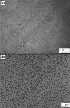
Fig.1 OM images of microstructures of base materials: (a) SiO2 glass ceramic; (b) TC4 alloy
tively. After joining, shear strength tests were performed by an Instron-1186 universal testing machine to assess the shear strength of the brazed joints. The specimens were compressed by the testing machine with a constant speed of 0.5 mm/min. The assembly of shear strength tests of the brazed sample is shown in Fig.2. The surface of cross section of joint was finally polished by 0.5 ��m diamond paste. The microstructure and fracture surface were examined with an optical microscope and an S-4700 scanning electron microscope (SEM) equipped with an energy dispersive spectrometer (EDS) and an electron probe X-ray microanalyzer (EPMA). The structure of reaction interface was identified by XRD (JDX-3530M).
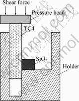
Fig.2 Schematic diagram of shear strength tests of SiO2/ TiZrNiCu/TC4 joint
3 Results and discussion
3.1 Identification of interface microstructure of brazed joint
Fig.3 shows the backscattered electron images of SiO2/TiZrNiCu/TC4 joint brazed at 950 �� for 5 min. The whole interface can be divided into three layers denoted by��, �� and ��, respectively. It can be seen from Fig.3(a) that layer �� covers most of the interface.
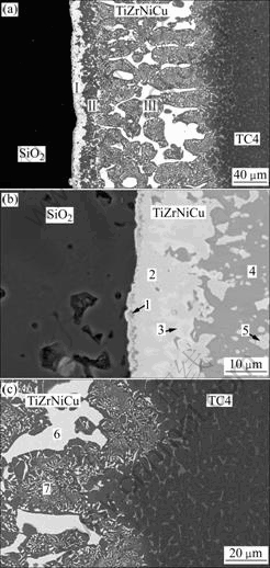
Fig.3 Backscattered electron images of interface of SiO2/ TiZrNiCu/TC4 joint brazed at 950 �� for 5 min: (a) Whole joint; (b) SiO2/TiZrNiCu interface; (c) TiZrNiCu/TC4 interface
To identify the interface products, composition analysis was carried out. Table 1 shows the average chemical compositions and possible reaction products in the joint brazed at 950 �� for 5 min. It can be known from Table 1 that layer ��mainly contains Ti, Zr, Ni, Cu, O, and Si, which shows that some SiO2 react with the braze alloy. Region 1 may be the reaction layer of SiO2 glass ceramic, Ti and Zr. While region 3 is the residual braze alloy. It can be seen from Table 1 that regions 4 and 5 on layer �� are composed of much Ti and O as well as a little Zr. The composition of layer �� is quite similar to that of TiZrNiCu braze alloy. Meanwhile, region 7 mainly consists of Ti-based solid solution (Ti (s.s)) and several kinds of intermetallic compounds.
To further confirm the types of reaction products, XRD analysis was performed in the following experiments. The XRD patterns of layers��, �� and �� are given in Fig.4. It can be known from Table 1 and Fig.4(a) that region 1 on layer��is composed of Ti2O+
Table 1 Average chemical compositions and possible reaction products in joint brazed at 950 �� for 5 min (mole fraction, %)
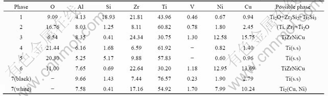
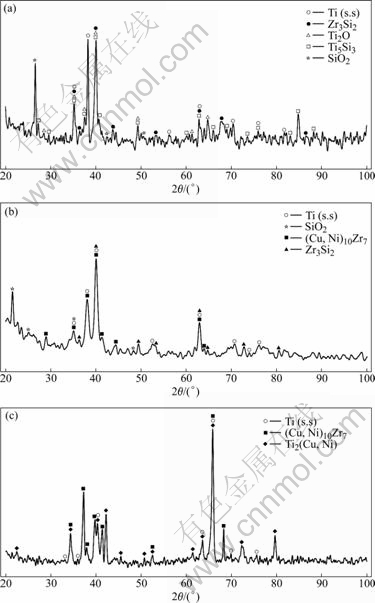
Fig.4 XRD patterns of different layers on SiO2/TC4 joint brazed at 950 �� for 5 min: (a) Layer��; (b) Layer ��; (c) Layer ��
Zr3Si2+Ti5Si3, while region 2 is composed of (Ti,Zr) solid solution and Ti2O. Regions 3 and 6 consist of TiZrNiCu. Layer �� (regions 4 and 5) is only composed of Ti (s.s). Region 7 is an eutectic product composed of Ti(s. s) and Ti2(Cu, Ni).Thus, it can be concluded that the interface structure of the SiO2 glass ceramic/TC4 joint brazed at 950 �� for 5 min can be described as SiO2 glass ceramic/Ti2O+ Zr3Si2+Ti5Si3/(Ti,Zr)+Ti2O+TiZrNiCu/Ti(s.s)/TiZrNiCu+Ti(s.s)+Ti2(Cu, Ni)/TC4 alloy.
3.2 Fracture path analysis of brazed joint
Fig.5 shows the shear strength under different brazing parameters. The joint strength increases first and then decreases as the brazing temperature or holding time increases. The maximum shear strength of joint reaches 23 MPa when the specimen is brazed at 880 �� for 5 min. Because the brazing temperature has a significant effect on the microstructure and mechanical properties of the joint, it is necessary to investigate the effects of brazing temperature on the shear strength and fracture behavior of joints.
When the brazing temperature is low, the interaction of parent material and braze alloy is not adequate, which leads to the weak interface connection (see Fig.6(a)). But for the joint brazed at 880 ��, the degree of interface reaction enhances and the thickness of the reaction layers is appropriate (see Fig.6(b)). Accordingly, the joint strength turns to be the best.
Fig.7 shows the effect of brazing temperature on the
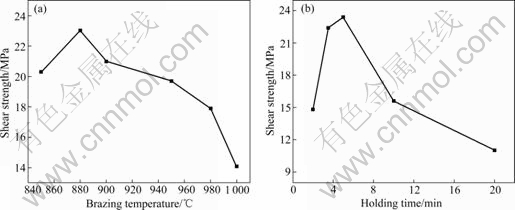
Fig.5 Effects of brazing parameters on shear strength of SiO2/TiZrNiCu/TC4 joints: (a) Brazing temperature (5 min); (b) Holding time (880 ��)
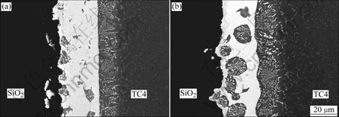
Fig.6 SEM images of interfaces at different brazing temperatures for 5 min: (a) 850 ��; (b) 880 ��
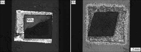
Fig.7 OM images of fractures of SiO2/TC4 joint brazed at different temperatures for 5 min: (a) 880 ��; (b) 980 ��
macrofracture of SiO2/TiZrNiCu/TC4 joint. It can be seen that fracture occurs at both SiO2 and SiO2/TiZrNiCu interface when the brazing temperature is 880 ��.Fig.8 and Table 2 give the microstructures of SiO2/ TiZrNiCu/TC4 fracture surface and the average chemical composition of fracture phase for the joint brazed at 880 �� for 5 min, respectively. It can be known from Fig.8 that the fracture surface consists of three areas (A, B and C). According to the results in Table 2, region A consists of SiO2 and region B is composed of residual filler metal and Ti2O+Zr3Si2+Ti5Si3 layer. The composition of region C is near to that of the braze alloy. Therefore, the crack expends along SiO2 glass ceramic and Ti2O+Zr3Si2+ Ti5Si3 reaction layer for the joint brazed at 880 �� for 5 min.
As shown in Fig.7(b), the fracture occurs only at the bonding interface for the joint brazed at 980 �� for 5 min. Fig.9 shows the magnification of the fracture surface. We can see that the fracture progresses in a single reaction layer according to Fig.9(a). The average chemical compositions of fracture phase are presented in Table 3, which indicates that the fracture is along Ti2O+Zr3Si2+
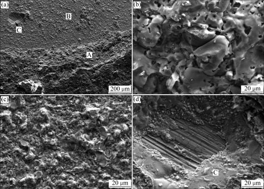
Fig.8 SEM images of fracture surfaces of SiO2/TC4 joint brazed at 880 �� for 5 min: (a) Whole surface; (b) Region A; (c) Region B; (d) Region C
Table 2 Average chemical compositions on fracture of joint brazed at 880 �� for 5 min (mole fraction, %)
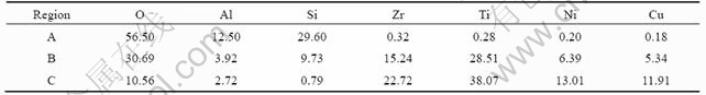
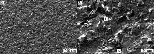
Fig.9 SEM images of fracture surfaces of SiO2/TC4 joint brazed at 980 �� for 5 min: (a) Whole surface; (b) Magnification of (a)
Table 3 Average chemical compositions on fracture of joint brazed at 980 �� for 5 min (mole fraction, %)
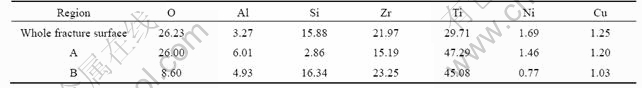
Ti5Si3 layer. Regions A and B consist of Ti-O compound and Ti-Si compound layer, respectively. The reason is that the thickness of the reaction layer increases with the increase of brazing temperature, which may easily lead to high residual stress in the Ti2O+Zr3Si2+Ti5Si3 layer between SiO2 and braze alloy. Therefore, microcrack tends to occur on Ti2O+Zr3Si2+Ti5Si3 layer (see Fig.10) after brazing.
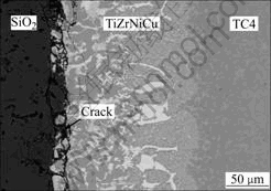
Fig.10 SEM image of crack at interface of SiO2/TiZrNiCu/TC4 joint
4 Conclusions
(1) SiO2 glass ceramic and TC4 alloy are brazed successfully using a commercially available TiZrNiCu filler foil.
(2) The interface structure is SiO2 glass ceramic/ Ti2O+Zr3Si2+Ti5Si3/(Ti,Zr)+Ti2O+TiZrNiCu/Ti(s.s)/TiZrNiCu+Ti(s.s)+Ti2(Cu, Ni)/TC4 alloy.
(3) The maximum shear strength of 23 MPa is obtained when the joint is brazed at 880 �� for 5 min.
(4) The fracture surface occurs on SiO2 glass ceramic and Ti2O+Zr3Si2+Ti5Si3 reaction layer when the brazing temperature is low, while the joint only fractures on Ti2O+Zr3Si2+Ti5Si3 layer as the brazing temperature increases.
References
[1] BOCCACCINI A R. Glass and glass-ceramic matrix composite materials: A review [J]. International Ceramic Review, 2002, 51(1): 24-35.
[2] ALIZADEH P, MARGHUSSIAN V K. Study of bulk crystallization in MgO-CaO-SiO2-NaS2O glasses in the presence of CaFS2 and MoO3 nucleant [J]. Journal of Materials Science, 2003, 38: 1529-1534.
[3] WOLFRAM H, VOLKER R, ELKE A, CHRISTIAN V H. Principles and phenomena of bioengineering with glass-ceramics for dental restoration [J]. Journal of the European Ceramic Society, 2007, 27(2/3): 1521-1526.
[4] PINAKIDOU F, KATSIKINI M, KAVOURAS P, KOMNINOU F, KARAKOSTAS T, PALOURA E C. Structural role and coordination environment of Fe in Fe2O3-PbO-SiO2-Na2O composite glasses [J]. Journal of Non-Crystalline Solids, 2008, 354(2/9): 105-111.
[5] FU Peng. Research and development of SiO2 ceramic [J]. Foshan Ceramics, 2007, 17(5): 30-33. (in Chinese)
[6] MORTERA R, ONIDA B, FIORILLI S, CAUDA V, BROVARONE C V, BAINO F, VERNE E, GARRONE E. Synthesis and characterization of MCM-41 spheres inside bioactive glass-ceramic scaffold [J]. Chemical Engineering Journal, 2008, 137(1): 54-61.
[7] LIANGShu-quan, TANXiao-ping, LIShao-qiang, TANGYan. Structure and mechanical properties of ZrO2-mullite nano-ceramics in SiO2-Al2O3-ZrO2 system [J]. Journal of Central South University of Technology, 2007, 14(1): 1-6.
[8] FENG Yun-zhi, WANG Ya-chong, TAN Yan-ni, LIU Yong, XIANG Qi-jun, SHENG Xiao-xian. Bioactivity of mica/apatite glass ceramics [J]. Trans Nonferrous Met Soc China, 2007, 17(4): 828-831.
[9] HUSSAIN P, ISNIN A. Joining of austenitic stainless steel and ferritic stainless steel to sialon [J]. Journal of Materials Processing Technology, 2001, 113: 222-227.
[10] TRAVESSA D, FERRANTEM M, DEN O G. Diffusion bonding of aluminium oxide to stainless steel using stress relief interlayers [J]. Materials Science and Engineering A, 2002, 337: 287-296.
[11] MESSLER R W, ORLING T T. Ceramic and metal jointed by functionally gradient alloy [J]. Advanced Materials and Processes, 1995, 147(6): 48-50.
[12] PRAKASH P, MOHANDAS T, RAJU P D. Microstructural characterization of SiC ceramic and SiC-metal active metal brazed joints [J]. Scripta Materialia, 2005, 52: 1169-1173.
[13] CHAKRAVARTY I, GUPTA S P. Formation of intermetallics during brazing of alumina with Fe, Ni and Cr using Ag-30Cu-30Sn as filler metal [J]. Materials Characterization, 2003, 51(4): 235-241.
[14] ZHANG Li-xia, FENG Ji-cai, HE Peng. Brazing temperature and time effects on the mechanical properties of TiC cermet/Ag-Cu-Zn/steel joints [J]. Materials Science and Engineering A, 2006, 428: 24-33.
[15] KIM J J, PARK J W, EAGAR T W. Interfacial microstructure of partial transient liquid phase bonded Si3N4-to-Inconel 718 joints [J]. Materials Science and Engineering A, 2003, 344: 240-244.
[16] SATO T, SEKI M, SHIMAKAGE K. Microwave joining of magnesia [J]. Journal of the Ceramic Society of Japan, 1996, 104(2): 155-157.
(Edited by CHEN Wei-ping)
Foundation item: Project(50705022) supported by the National Natural Science Foundation of China; Project(HIT0804) supported by the Foundation of the National Key Laboratory of Precision Hot Processing of Metals, China; Project supported by Program of Excellent Team in Harbin Institute of Technology, China
Received date: 2008-09-06; Accepted date: 2009-04-16
Corresponding author: ZHANG Li-xia, PhD; Tel: +86-451-86418146; E-mail: zhanglxia@hit.edu.cn
