

Preparation of porous Mg electrode by electrodeposition
ZHENG Wei-wei1, XU Qiang1, DING Fei2, ZHANG Jing2, LIU Xing-jiang1, 2
1. School of Chemistry Engineering and Technology, Tianjin University, Tianjin 300072, China;
2. Tianjin Institute of Power Sources, Tianjin 300381, China
Received 1 September 2010; accepted 16 December 2010
Abstract:
In order to obtain a porous Mg electrode with a stable skeleton, organic Mg fuel cell (OMFC), the electrochemical behavior of Mg deposition on Cu and Ni metallic substrates in 1 mol/L EtMgBr/THF solution was investigated by SEM, EDS and electrochemical methods. The experimental results show that Mg can be electrodeposited on both substrates, as a continuous layer on a Cu substrate. Accordingly, an approach for producing a porous Mg electrode with a stable skeleton of OMFC was proposed by means of electrodeposition of Mg on a foamed Ni substrate with a layer of Cu pre-plating. The discharge performance of this porous Mg electrode of OMFC is superior to that of a planar Mg electrode.
Key words:
magnesium electrodeposition; porous electrode; organic electrolyte; discharge performance;
1 Introduction
Among metals suitable for cells, Mg has advantages of high energy density, low density, low cost, abundance, and being environmentally friendly [1-3]. As a novel type of high specific energy power source, organic Mg fuel cells (OMFC) are considered ideal substitutes for traditional batteries; however, there are some challenges in improving the dynamic performance and the interface stability of the Mg electrode itself [4-6].
With the present development of Mg batteries, Mg electrodeposition technology has received intense attention [7-12]. Because of the negative electrode potential and high reaction activity of Mg, its electrodeposition was carried out only in organic electrolyte solutions. The corresponding plating solutions must be polar non-proton solvents, and moreover, there must be no reactions between the plating solutions and Mg [13-19].
Because the specific surface area of a porous electrode is larger than that of a planar electrode, the porous electrode has become a study focus of battery development [20-22]. In this work, we first studied the electrochemical behavior of Mg electrodeposition on different substrates (Ni, Cu), and then investigated the preparation of a porous Mg electrode with a stable skeleton of OMFC realized by the electrodeposition of Mg on a foamed Ni substrate with a layer of Cu pre-plating. The discharge performance of the resulting porous Mg electrode of OMFC was measured and investigated in detail.
2 Experimental
2.1 Preparation and electrochemical measurement of planar electrodes
The electrodeposition and performance measure- ments of Mg electrodes were carried out in an argon atmosphere glove box (MIKROUNA Advanced 2440/75), where the concentrations of water and oxygen were kept below 1��10-6 at room temperature.
Cyclic voltammetry and electrochemical impedance measurements were conducted in three-electrode cells inside the glove box at room temperature using a Solatron SI 1287/1260 electrochemical workstation. The working electrodes were Cu and Ni plates respectively (the area of the electrode was 0.26 cm2), while Mg foils (Mg purity 99.99%) served as both counter and reference electrodes. All of the electrodes were polished with a corundum suspension and rinsed with dry acetone before using.
The cyclic voltammetry scanning rate was 50 mV/s, and the scanning potential was controlled between -1.0 V and 1.9 V (vs Mg RE). The electrochemical impedance measurements were conducted at open potentials in a frequency range of 0.01 Hz-100 kHz, and the alternating current signal amplitude was 5 mV.
The surface morphology of Mg deposits was observed on a Hitachi S-4000 scanning electron microscope, and the surface components were analyzed by an HORIBA 7593-H energy-dispersive spectrometer.
The Grignard reagent (EtMgBr) was obtained from ACROS organics as a 1 mol/L solution in THF. Mg foils were prepared by machining a 99.99% pure Mg ingot (Jiuli Mg Co. Ltd.), and the Cu and Ni plates were of battery grade pure metals.
2.2 Preparation of Cu pre-plating coating and porous Mg electrode
Amperostatic electrodeposition of Cu was performed with a Solatron SI 1287/1260 electrochemical workstation in a electrolytic solution of pyrophosphate. The electrolytic solution was composed of potassium pyrophosphate (350 g/L), ammonium nitrate (20 g/L), and copper sulfate (90 g/L). The solution had pH of 8.5, and its temperature was controlled at 55 ��C. The current density was 15 mA/cm2 and the electrodeposition time was 3 min.
The substrate treatment process was as follows: acetone dip (5 min), distilled water wash; strong etching (30 s), distilled water wash; weak etching (2 min), distilled water wash; cathode polarization (5 mol/L KOH, 30 mA/cm2, 1 min), distilled water wash.
The strong etching solution was composed of KNO3, H2SO4 and HCl. The weak etching solution was H2SO4 (50 g/L). Amperostatic electrodeposition of Mg was carried out in three-electrode cells, the plating current density was 0.35 mA/cm2, and the plating time was 1 h. The porosity of the foamed Ni substrate (Battery grade) was above 98%.
2.3 Discharge performance of porous Mg electrode with stable skeletons
The potentiostatic discharge tests on planar and porous Mg electrodes were also carried out with the same system (three-electrode cell inside the glove box at room temperature, using a Solatron SI 1287/1260 Electrochemical Workstation). Both counter and reference electrodes were pure Mg plates, and the solution was 1 mol/L EtMgBr/THF. The discharge voltage was 0.5 V (vs Mg RE).
3 Results and discussion
3.1 Electrochemical behavior of Mg on different metal substrates
Figure 1 shows the cyclic voltammograms which were obtained through processes of electrodeposition and dissolution of Mg on Cu and Ni substrates in 1 mol/L EtMgBr/THF solution. These cyclic voltammograms indicate that the processes of electrodeposition and dissolution of Mg on both substrates can be realized in the system described above.
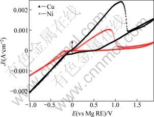
Fig. 1 Cyclic voltammograms of Mg deposition on Cu and Ni substrates (Scan rate: 50 mV/s)
Both these processes present a typical overpotential-driven nucleation/growth current loop, indicating that the electrodeposition of Mg on these substrates requires overpotential to initiate nucleation and subsequent growth of Mg. However, the figure also reveals pronounced differences in the cycling efficiency on the two substrates, particularly the overpotential required for Mg deposition, and the kinetics of the processes. As seen in Fig. 1, the electrodeposition of Mg on the Cu substrate can be observed at a potential below -0.1 V, while the electrodeposition on the Ni substrate begins at a potential below -0.25 V. Obviously, the overpotential of Mg electrodeposition on the Ni substrate is larger than that on the Cu substrate. At the same overpotential, the current density of Mg electrodeposition on the Cu substrate is also greater than that on the Ni substrate.
Figure 2 shows the typical Nyquist plots resulting from impedance measurements at open-circuit potential (OCV) at the beginning and end of Mg electrodepostion on Cu and Ni substrates. These impedance spectra indicate the adsorption processes and charge transfer on the electrode surfaces during Mg electrodeposition. For both substrates, the electrodeposition impedance value at the end of electrodeposition is lower than at the beginning, with the impedance values at the end in the order of hundreds of ��?cm2. Furthermore, these impedance spectra indicate that the resistance of Mg electrodeposition on the Ni substrate is larger than that on the Cu substrate.
3.2 Morphology and component analysis of Mg electrodeposition on planar substrates
Figure 3 shows the SEM images of Mg deposited on Cu and Ni substrates. It is visually evident that the surface morphologies are not the same on these substrates. There are some irregular coarse Mg particles dispersed unevenly on the Ni substrate, and the Mg deposits are not consecutive. On the contrary, Mg layers precipitated on the Cu substrate are compact and smooth.
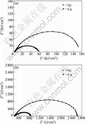
Fig. 2 Impedance spectra of Mg electrodeposition on Cu and Ni substrates: (a) At the beginning; (b) At the end
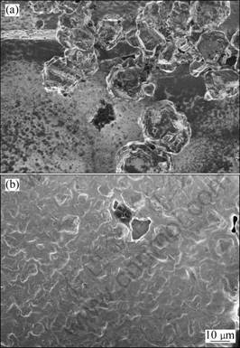
Fig. 3 SEM images of Mg deposits: (a) On Ni substrate; (b) On Cu substrate
The composition of deposits on both substrates was detected by EDAX. Mg is rarely found on a flat area of the Ni substrate; nevertheless, the average content of Mg particles on the Ni substrate is up to 72.6%. However, the deposits are more uniform on the Cu substrate than on the Ni substrate, with the average content of Mg on the Cu substrate around 84.9%.
Because the electrochemical activity of Ni is higher than that of Cu [20], the Ni substrate may react with the electrolytic solution easily, and a layer of thin oxide films can be formed between Mg deposits and the Ni substrate. Therefore, the deposition effect of Mg on the Cu substrate is better than that on the Ni substrate. Those analysis results of SEM and EDAX are consistent with the above discussion.
3.3 Morphology and component analysis of Mg electrodeposition on foamed substrates
Because the uniformity of Mg deposits is better on the Cu substrate than on the Ni substrate, the deposition of Mg on pure Ni could be enhanced if the substrate is clad with Cu.
Figure 4 shows the SEM image of the Cu coating on the planar Ni substrate. Most of the Ni substrate surface is clad with Cu, and the Cu coating surface morphology is continuous, smooth and compact.
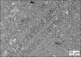
Fig. 4 SEM image of Cu plating coating on planar Ni substrate
In addition, a novel porous Mg electrode was prepared by the electrodeposition of Mg on a foamed Ni substrate. In order to increase the quantity of electrodeposited Mg, an intermediate layer of Cu pre-plating coating was electrodeposited between the foamed Ni substrate and the electrodeposits of Mg.
Figure 5 shows SEM images of the foamed Ni substrate, and the foamed Ni substrate with a layer of Cu pre-plating coating. The Cu pre-plating coating on the foamed Ni substrate has a surface morphology similar to that on the foamed Ni substrate, being continuous, smooth and compact. There are no nodules or particles on the surface of the Cu pre-plating coating. Components of the Cu pre-plating coating were analyzed by EDAX. The composition of the Cu pre-plating coating is uniform and the Cu content is up to 60%, both outside and inside the holes of the foamed substrate. These results indicate that the deep plating capability of the Cu-plating solution is excellent.
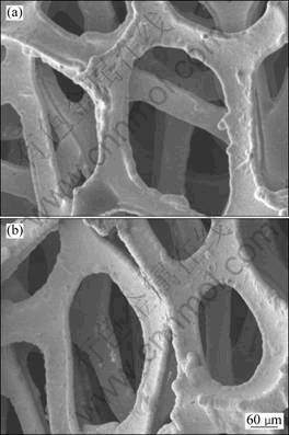
Fig. 5 SEM images of foamed substrate: (a) Ni substrate; (b) Cu-coated Ni substrate
Figure 6 shows the SEM image of a porous Mg electrode with a stable skeleton, which was prepared by electrodeposition of Mg on the formed Ni substrate with a layer of Cu pre-plating coating. Unlike the Cu pre-plating coating, the deposits of Mg are continuous and compact but coarse, and there are some nodules and particles on the surface. The composition of Mg deposits on the foamed substrate was also detected by EDAX, and the average content of Mg on the surface is 81.8%. However, the mean content of Mg inside the holes of the foamed substrate is 15.4%, indicating that the deep plating capability of the Mg-plating solution (EtMgBr/THF) is not good.
3.4 Discharge performance of porous Mg electrode with stable skeleton
Both planar and porous Mg electrodes were prepared according to the above methods (Sections 2.1 and 2.2) in 1 mol/L EtMgBr/THF solution. The adopted electrodeposition processes for both electrodes were the same with a current density of 0.35 mA/cm2, and a deposition time of 1 h. Test areas on both Mg electrodes were also the same at 0.26 cm2.
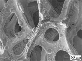
Fig. 6 SEM image of porous Mg electrode with stable skeleton
The potentiostatic discharge tests on both types of Mg electrodes were also carried out in three-electrode cells inside the glove box at room temperature, using the Solatron SI 1287/1260 Electrochemical Workstation. The discharging results are presented in Fig. 7. The potentiostatic discharge curves are not very flat because of the unevenness of Mg deposits. However, the trends of both curves indicate that the discharge current density of the porous Mg electrode is higher than that of the planar Mg electrode. This result may be attributed to larger specific surface area of the porous electrode than the planar electrode.
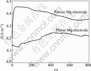
Fig. 7 Discharge performances of porous and planar Mg electrodes
4 Conclusions
1) The electrochemical deposition behaviors of Mg on Cu and Ni substrates in a solution of 1 mol/L EtMgBr/THF are obviously different, the deposits are more uniform on the Cu substrate than on the Ni substrate.
2) A novel porous Mg electrode with a stable skeleton of OMFC could be prepared by electrodeposition of Mg on a foamed Ni substrate with an intermediate layer of Cu pre-plating coating, and the discharge performance of the porous Mg electrode of OMFC is apparently superior to that of the planar Mg electrode.
References
[1] LI Wei-yang, LI Chun-sheng, ZHOU Chun-yuan, MA Hua, CHEN Jun. Metallic mgnano/mesoscale structures: Their shape-controlled preparation and Mg/air battery applications [J]. Angewandte Chemie International Edition, 2006, 45: 6009-6012.
[2] CAO Dian-xue, WU Lin, WANG Gui-ling, LV Yan-zhuo. Electrochemical oxidation behavior of Mg-Li-Al-Ce-Zn and Mg-Li-Ce-Zn-Mn in sodium chloride solution [J]. Journal of Power Sources, 2008, 183: 799-804.
[3] PANDEY G P, HASHMI S A. Experimental investigations of an ionic-liquid-based, magnesium ion conducting, polymer gel electrolyte [J]. Journal of Power Sources, 2009, 187: 627-634.
[4] VIESTFRID Y, LEVI M. D, GOFER Y, AURBACH D. Microelectrode studies of reversible magnesium deposition in THF solutions containing complexes of alkylaluminum chlorides and dialkylmagnesium[J]. Journal of Electroanalytical Chemistry, 2005, 576: 183-195.
[5] FENG Zhen-zhen, NULI Yan-na, WANG Jiu-lin, YANG Jun. Study of key factors influencing electrochemical reversibility of magnesium deposition and dissolution [J]. Journal of Electrochemistry Society, 2006, 153: C689-C693.
[6] MEDERIOS M G, DOW E G. Magnesium-solution phase catholyte seawater electrochemical system [J]. Journal of Power Sources, 1999, 80: 78-82.
[7] AMIR N, VESTFRID Y, CHUSID O, GOFER Y, AURBACH D. Progress in nonaqueous magnesium electrochemistry [J]. Journal of Power Sources, 2007, 174: 1234-1240.
[8] MIZRAHI O, AMIR N, POLLAK E, CHUSID O, MARKS V, GOTTLIEB H, LARUSH L, ZINIGRAD E, AURBACH D. Electrolyte solutions with a wide electrochemical window for rechargeable magnesium batteries [J]. Journal of Electrochemistry Society, 2008, 155: A103-A109.
[9] NULI Yan-na, YANG Jun, WU Rong. Reversible deposition and dissolution of magnesium from BMIMBF4 ionic liquid [J]. Electrochemistry Communications, 2005, 7: 1105-1110.
[10] WANG Pu, NULI Yan-na, YANG Jun, FENG Zhen-zhen. Mixed ionic liquids as electrolyte for reversible deposition and dissolution of magnesium [J]. Surface and Coatings Technology, 2006, 201: 3783-3787.
[11] AURBACH D, GIZHAR H, SCHECHTER A, CHUSID O, GOTTLIEB H E, GOFER Y, GOLDBERG I. Electrolyte solutions for rechargeable magnesium batteries based on organomagnesium chloroaluminate complexes [J]. Journal of Electrochemistry Society, 2002, 149: A115-A121.
[12] LIEBENOW C, YANG Z, LOBITZ P. The electrodeposition of magnesium using solutions of organomagnesium halides, amidomagnesium halides and magnesium organoborates [J]. Electrochemistry Communication, 2000, 2: 641-645.
[13] LOSSIUS L, EMMENEGGER P F. Plating of magnesium from organic solvents [J]. Electrochimica Acta. 1996, 41: 445-447.
[14] LIEBENOW C. Reversibility of electrochemical magnesium deposition from Grignard solutions [J]. Journal of Applied Eletrochemistry, 1997, 27: 221-225.
[15] LU Z, SCHECHTER A, MOSHKOVICH M, AURBACH D. On the electrochemical behavior of magnesium electrodes in polar aprotic electrolyte solutions [J]. Journal of Electroanalytical Chemistry, 1999, 466: 203-217.
[16] AURBACH D, COHEN Y, MOSHKOVICH M. The study of reversible magnesium deposition by in situ scanning tunneling microscopy [J]. Electrochemical and Solid-State Letters, 2001, 4: A113-A116.
[17] AURBACH D, LU Z, SCHECHTER A, GOFER Y, GLZBAR H, TYRGEMAN R, COHEN Y, MOSHKOVLCH M. Prototype systems for rechargeable magnesium batteries [J]. Nature, 2000, 407: 724-727.
[18] AURBACH D, TURGEMAN R, CHUSID O, GOFER Y. Spectroelectrochemical studies of magnesium deposition by in situ FTIR spectroscopy [J]. Electrochemistry Communications, 2001, 3: 252-261.
[19] AURBACH D, SCHECHTER A, MOSHKOVICH M, COHEN Y. On the mechanisms of reversible magnesium deposition processes [J]. Journal of Electrochemistry Society, 2001, 148: A1004-A1014.
[20] LINDEN D, REDDY T B. Handbook of batteries [M]. 3rd ed. New York: McGraw-Hill, 2002.
[21] ROMANN T, LUST E. Electrochemical properties of porous bismuth electrodes [J]. Electrochimica Acta, 2010, 55: 5746-5752.
[22] ZHANG Song, BEAN T, EDWARDS D B. Examination of different lattice structures in porous electrodes using a three-dimensional conductivity model [J]. Journal of Power Sources, 2010, 195: 883-889.
��������Ʊ����þ�缫
֣ΰΰ1���� ǿ1���� ��2���� ��2�����˽�1, 2
1. ����ѧ ����ѧԺ����� 300072��
2. ����Դ�����о�������� 300381
ժ Ҫ��Ϊ���Ʊ�һ�ֹǼ��ȶ����л�þȼ�ϵ�ض��þ�缫��ͨ��ɨ��羵�����������绯ѧ�����о�����1 mol/L EtMgBr/THF�ĵ������Һ�У�þ�ڽ�������ͭ2�ֻ����ϳ����ĵ绯ѧ��Ϊ�����������þ��2�ֽ��������Ͼ����Է���������������ͭ�����ϻ��ܹ��γ�һ�������ĶƲ㡣������Ԥ��ͭ����ĭ�������ϵ����þ�ķ����Ʊ���һ�����Ǽ��ȶ��Ķ��þ�缫�����ֶ��þ�缫�ķŵ���������ƽ��״��þ�缫��
�ؼ��ʣ�þ���������缫���л�����ʣ��ŵ�����
(Edited by LI Xiang-qun)
Foundation item: Project (20973124) supported by the National Natural Science Foundation of China
Corresponding author: XU Qiang; Tel: +86-22-27890322; E-mail: xuqiang_tj@163.com; LIU Xing-jiang; E-mail: klpsc@yahoo.com.cn
DOI: 10.1016/S1003-6326(11)60979-5
