
J. Cent. South Univ. Technol. (2011) 18: 697-703
DOI: 10.1007/s11771-011-0750-2![]()
Development of XY scanner with minimized coupling motions for high?speed atomic force microscope
PARK Jong-kyu1, MOON Won-kyu2
1. Department of Mechanical Engineering, Changwon National University, Changwon, 641-773, Korea;
2. Department of Mechanical Engineering, Pohang University of Science and Technology, Pohang, 790-784, Korea
? Central South University Press and Springer-Verlag Berlin Heidelberg 2011
Abstract:
The design and fabrication processes of a novel scanner with minimized coupling motions for a high-speed atomic force microscope (AFM) were addressed. An appropriate design modification was proposed through the analyses of the dynamic characteristics of existing linear motion stages using a dynamic analysis program, Recurdyn. Because the scanning speed of each direction may differ, the linear motion stage for a high-speed scanner was designed to have different resonance frequencies for the modes, with one dominant displacement in the desired directions. This objective was achieved by using one-direction flexure mechanisms for each direction and mounting one stage for fast motion on the other stage for slow motion. This unsymmetrical configuration separated the frequencies of two vibration modes with one dominant displacement in each desired direction, and hence suppressed the coupling between motions in two directions. A pair of actuators was used for each axis to decrease the crosstalk between the two motions and give a sufficient force to actuate the slow motion stage, which carried the fast motion stage. A lossy material, such as grease, was inserted into the flexure hinge to suppress vibration problems that occurred when using an input triangular waveform. With these design modifications and the vibration suppression method, a novel scanner with a scanning speed greater than 20 Hz is achieved.
Key words:
atomic force microscope; scanner; piezoelectric stack actuator; crosstalk; flexure hinge��
1 Introduction
High-speed ultra-precision positioning technology is important for developing new technologies for devices such as integrated circuit fabrication equipment, micro/nanoelectromechanical systems (MEMS/NEMS), optoelectronic devices, and scanning probe microscopes (SPMs)[1]. A typical application of this technology is moving samples in the X and Y directions with a scanner in an atomic force microscope (AFM). This application has contributed to the development of nanotechnology by imaging atoms on the surfaces of samples. An AFM has the best resolution among conventional imaging devices. However, although optical microscopes can observe a sample in real time, an AFM requires a few minutes to scan the image. One of the main reasons for this is the speed of the scanner.
To increase the speed and accuracy of the scanner, conflicting requirements must be satisfied, such as a high first-resonance frequency, long travel range, and high positioning accuracy. In particular, the piezoelectric actuators for the scanner have such a small displacement that an amplification mechanism must be used to cover the long travel range. However, the amplification mechanism can lower the natural frequency of the system. As the actuation frequency increases, the crosstalk between the X- and Y?motion axes introduces severe displacement errors. Therefore, complicated design procedures must be performed to achieve the design goals, and various simulation packages are required.
AFM scanners can be categorized into three types: piezoelectric tubes [2-4], linear motion stages actuated by the piezoelectric stack [5-8], and electrostatic comb drives [9]. Currently, most scanners used in AFMs are piezoelectric tube actuators. However, conventional AFM tube scanners are not adequate for high-speed scanning due to the interference between their X- and Y-direction motions and the presence of unwanted vibrations [5]. Recently, linear-motion stage scanners have been adopted for commercial AFMs due to their flat scanning surface, minimal unwanted motion, and ease of control. Because a linear-motion stage scanner is actuated by piezoelectric stacks through a flexure-hinge- guided mechanism, it may have a fundamental vibration coupling mode in the two moving directions desired to be independent. Therefore, it may also have problems to achieve high-speed operations, similar to a tube scanner.
Appropriate design modifications are proposed to a linear-motion scanner so that the displacements in the two directions are dynamically independent. This can be achieved by combining two uni-directional flexure mechanisms: a smaller linear-motion stage for high-speed scanning in one direction mounted on a larger stage for slow scanning in the orthogonal direction. The natural frequencies of the modes can differ sufficiently to reduce the coupling effects when the dominant displacements are in two independent directions.
2 Design procedure
2.1 Scanner mechanism
A scanner is basically composed of a flexure-hinge guiding structure and stack actuators. The actuation mechanism is quite simple. First, an input voltage signal induces motion in the stack actuator. Then, the stack actuator pushes one end of a lever mechanism; the other end of this mechanism pushes, in turn, a stage conveying a sample while the other various flexure links are restrained from unwanted motions.
A flexure-hinge guiding system minimizes unwanted motions using the elastic motions of a broad range of the compliant elements connecting the rigid bodies [10-15]. Flexure-hinge guiding systems have been widely used in nano-positioning applications due to several merits. First, design modifications are possible by changing the stiffness and layout because the systems have monolithic structures. Second, because the body deformation is infinitesimally small, the resolution is extremely high. The systems have no friction or wear motion, and hence there is no actuation dead zone. Finally, the systems can use a displacement amplification mechanism such as a lever mechanism.
A stack actuator basically transforms electrical energy into mechanical energy to raise the displacement of a scanner. A stack actuator is made of numerous thin multi-layers and can be actuated with a low voltage. It can exert a relatively large force and displacement. However, it has demerits: 1) it has nonlinear properties such as hysteresis, and 2) its pushing force is greater than its pulling force so that it needs an appropriate preload to compensate. A stretched spring is generally used as the preload, and the spring stiffness should be smaller than 1/10 of the stack stiffness because it must not influence the stack displacement.
2.2 Design procedure
Several design parameters must be considered for an effective high-speed scanner. First, the stack actuator and flexure must be stiff because the first natural frequency of the scanner is determined by the first natural frequency of the stack actuator and flexure system. Second, the crosstalk between the two independent motions of the stage must be suppressed to achieve undistorted motions. Although it is impossible to eliminate the crosstalk completely, it should be minimized by changing the layout of the X and Y axes. The induced vibrations based on the input waveform constitute other unwanted motions. If the input voltage is a sine waveform, a vibration problem does not occur because sine waves have no abrupt acceleration changes. But, the problem is unavoidable with a triangular waveform because the corners of the waves are non-differentiable points. The generated vibration is associated with the first natural frequency of the scanner system.
Figure 1 shows a conventional scanner composed of two actuators, one platform, and flexure links. Its mechanism consists of two actuators that push the platform simultaneously through a lever mechanism.
The layout of the scanner has the same resonance frequency and symmetric structure about each axis. Its merits are that its users can predict the mutual relationship between the motions on each axis and that it occupies a relatively small space. However, the symmetric layout introduces problems because rotational motion can be generated by the lever mechanism, causing crosstalk.
The operating principle of an AFM scanner dictates that if a sample is 256 ��m ? 256 ��m and the resolution is 256 ? 256, the X-axis scanner moves only 1/512 of a cycle while the Y-axis scanner scans one entire cycle. Therefore, the Y-scan frequency is 512 times the X-scan frequency.
By analyzing the scanners and AFM mechanisms, a scanner with an unsymmetrical configuration can be designed so that the natural frequencies of the X and Y scanners are different. Hence, the stage devised in this work (Fig.2) consists of a flexure system with a monolithic structure, two piezoelectric actuators per axis, and two preload springs in each direction for a total of four actuators and four springs. The monolithic flexure system includes X- and Y-axis platforms with lever mechanisms and flexure leaf springs, which are divided by a 0.3 mm-wide border line (Fig.2). Four U-shaped flexure-leaf springs per axis guide the platform in the desired direction, constraining unwanted motion. The Y stage is mounted on the X stage. Each lever mechanism is made up of fulcrums, levers, and flexure pivots that transfer force and displacement to the platforms. If the input voltage is applied to the two actuators, the actuators simultaneously expand and push the lever through the flexure pivots. The lever beams rotate when the fulcrum pivot pushes the platform through the flexure pivots. Using this imbedded layout, the system can be designed so that the natural frequencies of each axis are different from each other, minimizing their crosstalk.
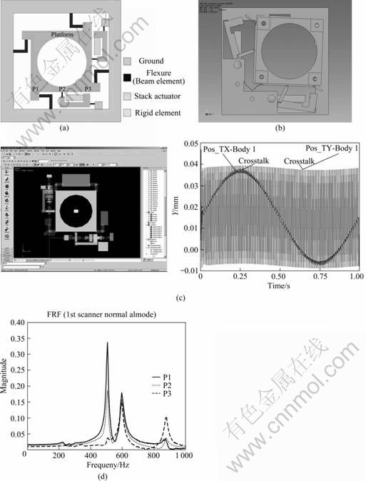
Fig.1 Schematic diagram (a), static (b) and dynamic simulation (c), and frequency response function (d) of conventional scanner
Our system is too complicated to model mathematically because two axes must be solved simultaneously. Therefore, the Y stage is only modeled mathematically because the X and Y stages have very similar actuating mechanisms.
A flexure hinge can be modeled as a spring, whereas a platform can be modeled as a rigid mass. A piezoelectric stack actuator can also be modeled as a mass-spring system. Because this model is similar to the levered flexure mechanism of WOODY and SMITH [13], their approach was used in this study. First, the equivalent generating force and stiffness were calculated to model the piezoelectric actuators mathematically. The piezoelectric constitutive relationships are
![]() (1)
(1)
where F and V are external force and voltage; �� and q are displacement and charge, respectively; the coefficients am, ame, and ae can be calculated from the material properties supplied by the manufacturer.
The stiffness of the piezoelectric actuators, kp, can be calculated by
![]() (2)
(2)
![]() (3)
(3)
![]() (4)
(4)
The first resonance frequency of the scanner is calculated as follows. The amplification ratio of the displacement is defined as n, which can be theoretically expressed as
![]() (5)
(5)
where xy is the displacement of the Y platform and xp is the displacement of the piezoelectric stack actuator. The lever length ratio is b over a, as shown in Fig.2:
![]() (6)
(6)
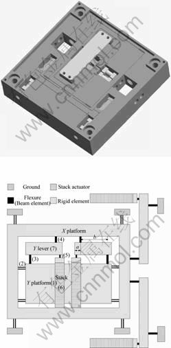
Fig.2 Schematic diagram of novel scanner
Small rotational angle may be expressed as
![]() (7)
(7)
Based upon this model, the kinetic energy may be expressed as
![]() (8)
(8)
Where the second moment of mass of the rotating level arm is denoted as IL with a mass of mL.
Next, the potential energy equation may be expressed as
![]()
![]() (9)
(9)
where kR is the sum of the rotational stiffness of each hinge (Fig.2, parts 3, 4 and 5),
![]() , ky=4��(k1)b,
, ky=4��(k1)b, ![]()
The equation governing free motion can be obtained from the Lagrange equation. Evaluating Eqs. (8) and (9), the equation governing the free motion of this flexure is
![]()
![]() (10)
(10)
Therefore, the natural frequency is given by
 (11)
(11)
Although the derived natural frequency gives only an approximate result, it is mainly dependent on the stiffness of the piezoelectric actuators (kp), the mass of stage (my) and the amplification ratio (n).
3 Simulations
Simulations were conducted to predict more accurate experimental results using two types of commercial packages. Some simplifications were made for the stack actuator and its point of contact, as this component is difficult to model exactly. Because a stack actuator is an electromechanical coupling system, the equivalent elastic modulus and force must be determined. In addition, there is no established modeling method for the contact between the stack actuator and flexure hinge, even though it can affect the simulation results. Consequently, because a point contact is not offered in our software package, a bonded surface contact is used, which gives a stiffening effect.
Static and dynamical analyses were performed using a finite element method package (Cosmosworks, Solidworks Co.) with the four corner holes fixed as a boundary condition. The first vibration mode was translation in the Y direction at 333 Hz; the second mode was translation in the X direction at 571 Hz (Fig.3), which meant that crosstalk was minimized for dynamic actuation. This was different from conventional scanners with a coupled XY mode.
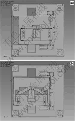
Fig.3 Finite element analysis of flexure system: (a) 333 Hz; (b) 571 Hz
An additional dynamic analysis was required because the previous finite element model could not give the time domain data of the position to calculate the displacement, velocity and force. In particular, the crosstalk between the X and Y motions was evaluated by the dynamic analysis. Accordingly, a discrete mass dynamic package (Recurdyn) was used. The flexure hinge was modeled as a Timoshenko beam element [14-15], and the platform and lever beam were modeled as a rigid element. The displacement was expected to be about 45 ?m for the Y-axis stage and 40 ?m for the X-axis stage. As shown in Fig.4, it is verified that the crosstalk decreases considerably, which is different from conventional scanners. As determined from the static analysis, straighter motion can be generated with two actuators per axis rather than a single actuator used for conventional scanners.
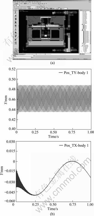
Fig.4 Dynamic analysis of flexure system for checking crosstalk: (a) Dynamic modeling; (b) Simulation result
4 Experiment and results
The experiment was conducted to verify the static and dynamic characteristics of the scanner, which was fabricated using wire with 0.3 mm in diameter cut from 6061 aluminum alloy. The equipment used in this test is illustrated in Fig.5. First, a frequency sweep of 5 Vpp was supplied as an input with a 2.5 V offset using a Stanford SRT785 FFT analyzer to measure the frequency response of a 1 kHz frequency span. Second, an HP 33120A function generator and HSA 4052 (NF Corporation) and Kepco voltage amplifiers were used to measure the time response for 20 V and 100 V input. The displacement was measured using laser Doppler velocimetry (LDV) (Polytec) with a 2 nm resolution. The piezoelectric stack actuator was a Tokin AE0505D16.
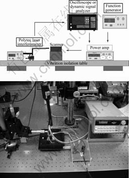
Fig.5 Experimental setup for measuring time response of scanner
The natural mode and frequency results are presented as frequency response functions (FRFs), which are determined at about three points to calculate the natural mode. As shown in Fig.6, the first resonance frequency is 212.97 Hz in the Y axis and 596.52 Hz in the X axis. This FRF shows that the first mode is almost a translation in the outer axis. Although there is rotational motion in the inner axis, it is smaller than that found in a conventional scanner, as expected from the simulations (Fig.6).
The time response is calculated using sine and triangular waveforms. For the sine waveform, it is verified that the scanner has good tracking response to more than 100 Hz (Fig.7). The output displacement at 100 V is measured to be 30 ��m in the inner X axis and about 50 ��m in the outer Y axis.
For the triangular waveform, vibrations occur because the corners of the waveform are non-differentiable and have infinite acceleration. Vibrations are conspicuous at >30 Hz for the inner X axis and >5 Hz for the outer Y axis. This problem can be suppressed by several methods. The first method is to dampen the response by introducing a highly viscous material such as grease into the flexure. The second method is to round off the corner of the triangular waveform. The third method is to use active damping by feedback [5]. In this work, the first method is used, which can reduce the vibration of the inner X axis, as shown in Fig.8. The advantage of this method is that additional devices, such as control circuits, are not required. As a result, the stage could be scanned at a speed of more than 50 Hz.
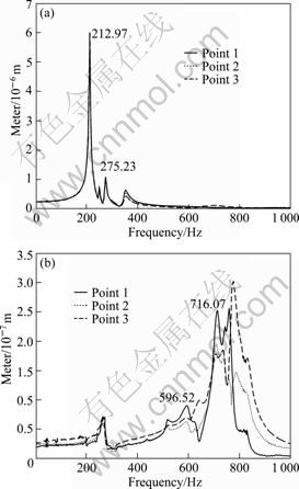
Fig.6 Frequency response functions of Y axis (a) and inner X axis scanners
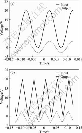
Fig.7 Time response of Y (a) and X (b) axis scanners
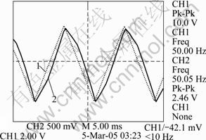
Fig.8 Time response after inserting lossy material (50 Hz/100 V triangular waveform)
5 Conclusions
1) Two uni-directional flexure-hinge mechanisms were adopted so that the Y-axis stage could be embedded in the X-axis stage. In addition, the natural frequencies of the fundamental modes of the two mechanisms were designed. The natural frequency of the X-axis stage is 212.97 Hz, whereas that of the Y-axis stage is 596.52 Hz. This configuration makes it possible to reduce the coupling effects to <0.1%. Therefore, the scanner can be operated at a scanning speed of more than 20 Hz with a sine waveform input.
2) Two actuators were used for each axis to push the platforms (stages) symmetrically. In this novel scanner, a displacement of about 50 ��m in the Y direction and about 30 ��m in the X direction is achieved by using amplification mechanisms whose fulcrums are integrated in a monolithic-flexure-hinge system. The maximum scanning speed is more than 10 times faster than that achieved by conventional scanners.
References
[1] SPANNER K, VOMDRAN S. Advances in piezo-nanopositioning technology [C]// Proceedings of IEEE/ASME Conference on Advanced Intelligent Mechatronics. Kobe, Japan, 2003: 1338-1343.
[2] SCHITTER G, STEMMER A. Model-based signal conditioning for high-speed atomic force and friction force microscopy [J]. Microelectro Eng, 2003, 67/68: 938-944.
[3] GEORG S, PHILIOPP J T, PAUL K H. Design and input-shaping control of a novel scanner for high-speed atomic force microscopy[J]. Mechatronics, 2008, 18: 282-288.
[4] GEORG E, GEORG S, JOHANNES H, TZVETAN I, KATARINA I, ROH P, NIELS H, JONATHAN A, PHILIPP T, IVO W, PAUL K. Components for high speed atomic force microscopy[J]. Ultramicroscopy, 2006, 106: 881-887.
[5] KWON J, HONG J, KIM Y, LEE D, LEE K, LEE S, PARK S. Atomic force microscope with improved scan accuracy, scan speed, and optical vision[J]. Rev Sci Instrum, 2003, 74: 4378-4383.
[6] LEE D, Kwon D. Development of a two-axis flexure-guided nano-stage [C]// Proceeding of Korean Society of Mechanical Engineers. Pyeongchang, Korea, 2008: 13-18.
[7] KWON G, KIM S, JEONG M, HAN S, CHOI C, HAN S, HONG J, LEE H. High-speed atomic force microscope lithography using a piezo tube scanner driven by a sinusoidal waveform[J]. Ultramicroscopy, 2009, 109: 1052-1055.
[8] TOSHIO A, NORIYUKI K, DAISUKE M, EISUKE T, KIWAMU S, AKITOSHI T. A high-speed atomic force microscope for studying biological macromolecules in action[J]. ChemPhysChem, 2003, 4: 1196-1202.
[9] ANDO Y. Development of three-dimensional electrostatic stages for scanning probe microscope[J]. Sensors and Actuators A: Physical, 2004, 114: 285-291.
[10] SALAPAKA S, SEBASTIAN A, CLEVELAND J P, SALAPAKA M V. High bandwidth nano-positioner: A robust control approach [J]. Rev Sci Instrum, 2002, 73: 3232-3241.
[11] DONG W, SUN L N, DU Z J. Design of a precision compliant parallel positioner driven by dual piezoelectric actuators [J]. Sensors and Actuators A: Physical, 2007, 135: 250-256.
[12] YANLING T, BIJAN S, DAWEI Z, GURSEL A. Development and dynamic modelling of a flexure-based Scott�CRussell mechanism for nano-manipulation [J]. Mechanical Systems and Signal Processing, 2009, 23: 957-978.
[13] WOODY S C, SMITH S T. Performance comparison and modeling of PZN, PMN, and PZT stacked actuators in a levered flexure mechanism [J]. Rev Sci Instrum, 2004, 75: 842-848.
[14] SMITH S T. Flexures Elements of Elastic Mechanism Design [M]. Amsterdam: Gordon and Breach, 2002: 48-52.
[15] ODEN J T, RIPPERGER E A. Mechanics of Elastic Structures[M]. 2nd ed. New York: McGraw-Hill, 1968: 35-55.
(Edited by YANG Bing)
Foundation item: Work(R0A-2007-000-20042-0) partly supported by the Second Stage of Brain Korea 21 Projects, and partly by the Korea Science and Engineering Foundation (KOSEF) through the National Research Laboratory Program funded by the Ministry of Science and Technology of Korea
Received date: 2010-03-08; Accepted date: 2010-06-24
Corresponding author: PARK Jong-kyu, Assistant Professor, PhD; Tel: +82-55-213-3608; E-mail: chong@changwon.ac.kr
