
Trans. Nonferrous Met. Soc. China 27(2017) 2406-2414
Simulation of critical cooling rate and process conditions for metallic glasses in vertical type twin-roll casting
Zhi-pu PEI1, Dong-ying JU2,3 , Xue LI3
1. Graduate School of Saitama Institute of Technology, Fusaiji 1690, Fukaya, Saitama 369-0293, Japan;
2. Department of Material Science and Engineering, Saitama Institute of Technology, Fusaiji 1690, Fukaya, Saitama 369-0293, Japan;
3. School of Materials and Metallurgy, University of Science and Technology Liaoning, Anshan 114051, China
Received 11 October 2016; accepted 21 June 2017
Abstract:
Critical cooling rates for producing metallic glasses were evaluated based on a calculated continuous cooling transformation (CCT) diagram. Temperature distributions of the melt in molten pool in the vertical type twin-roll casting (VTRC) process of metallic glasses were simulated, and cooling rates under different casting conditions were calculated with the simulated results. By comparing the results obtained by CCT diagrams and simulation, the possibility of producing metallic glasses by the VTRC method and influences of casting conditions on cooling rate were discussed. The results reveal that cooling rate with 3 or 4 orders of magnitude by the VTRC process can be attained in producing Mg-based metallic glasses, which is faster than the critical cooling rate calculated by the CCT diagram. One side pouring mode can improve the temperature distributions of casting pool. VTRC process has a good ability in continuous casting metallic glassy thin strips.
Key words:
metallic glass; critical cooling rate; twin-roll casting; simulation;
1 Introduction
In continuous producing wide metallic ribbon process, a single wheel or a twin-roller configuration is commonly adopted. It first came to be a topic of considerable interest in the 1970s [1,2], and now the improvements and variations of the process are known as melt spinning and twin-roll strip casting [3-6]. The melt spinning process involves the lips of nozzle held very close to the rotating wheel to attain wide sheets, and this will make the requirement in nozzle chosen strictly. Contrarily, in the twin-roll casting process, molten metal is fed through two rotating rolls, and the formation of the final strip is controlled by the rolls nip. So, the question of nozzle is no longer rigorous.
Over the past decade, many studies have been carried out on the fabrication of bulk amorphous alloy sheets via twin-roll casting (TRC) method [3-6]. It turns out that TRC is an available process for producing amorphous alloy sheets with a wide range of cooling rates. Well, nearly all the studies so far are based on horizontal type twin-roll casters. Previous studies showed that the casting speed of vertical type twin-roll casting (VTRC) is higher than that of the horizontal type twin-roll casting (HTRC), and the heat transmission of the VTRC is more effective [7-10]. As the properties of Vit-1 alloys (Zr41.2Ti13.8Cu12.5Ni10.0Be22.5) are extensively characterized at low critical cooling rate (i.e., 1 K/s), they are widely used in the studies of TRC of bulk metallic glasses processes. And most of them are HTRC processes with casting speed of 1.6-2.1 m/min [3,4,6,11]. However, as for the alloys with less experimental data which could not be tested easily, numerical computation seems to be a good method because adjustment of process conditions, observation of phenomena and obtainment of results are more convenient. As mentioned above, heat transmission of VTRC is more effective than HTRC, and a wide range of variable casting speed could also be attained by VTRC process. VTRC technique would be an effective method for producing metallic glass sheets continuously.
As lightweight structural materials, Mg-based alloys exhibit excellent properties (e.g., high specific strength and good electromagnetic shield abilities) and are interesting materials in many fields. Especially Mg-based metallic glasses as bioresorbable metals are exhibiting an increasingly interest in research and development of biodegradable implants [12]. In this work, based on a vertical pilot twin-roll caster with roll radius of 150 mm and roll width of 100 mm, temperature distributions of the molten pool during casting magnesium alloy under different conditions were obtained using thermal-flow simulation method. With the simulated results, the ability to produce Mg-based metallic glasses by VTRC process was estimated using a calculated continuous cooling transformation (CCT) diagram. And the influences of casting parameters were also discussed.
2 Calculation of time reduced-temperature transformation and CCT diagrams
2.1 Calculation of time reduced-temperature transformation diagram
The expression ��glass��, in its original sense, refers to an amorphous or non-crystalline solid formed by continuous cooling of a liquid, while a solid is defined as any body having a viscosity greater than a somewhat arbitrary 1��1013 Pa��s [13]. The viscosity of supercooled liquid metals, ��(T), is commonly described by the Vogel-Fulcher-Tammann (VFT) relation:
 (1)
(1)
where T0 is an ideal glass transition temperature, B is a constant depending on materials, T is the temperature, ��0 has the relation of ��0=NAh/V, with NA, Avogadro constant, h, Planck constant and V, the molar volume [14]. In this work, V is calculated by the JMatPro software firstly (as shown in Fig. 1) and values above the liquidus temperatures are adopted. Then, we can get ��0 of each alloy, as listed in Table 1. It is found that the value of B is small in liquid metals, and T0 is a substantial fraction (e.g., ~1/3 to 2/3) of melting temperature Tm [13]. D* is the fragility parameter (1��D*��100). Liquids are commonly referred to as ��fragile�� when D*?10 and ��strong�� when D*?20 [15].
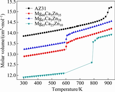
Fig. 1 Molar volume of Mg-based alloys
Table 1 Parameters used for calculation of time reduced-temperature transformation diagram for magnesium alloy
Equation (2) [16] gives a time transformation curve (C-curve) that


 (2)
(2)
expresses the time to transform to crystal as a function of temperature. Here, k is the Boltsmann constant, x is the fraction of crystal formed in time t, and a volume fraction of 1��10-6 as a just-detectable concentration of crystals was used [17]. a0 is the mean atomic diameter, Nv is the volume concentration of atoms. Tr (=T/Tm) is the reduced-temperature, and ��Tr(=1-Tr) is the reduced- undercooling of the melt. Br and T0r and ��0r are defined as B/Tm, T0/Tm and ��0/Tm, respectively. The first term of Eq. (2) is considered a constant [16], in this work, it is 0.89��10-6 K��m3/J. Since B and T0 are empirical parameters and are not known clearly for the alloys below, they have pronounced effects on the outcome of the calculations. In order to estimate a more appropriate C-curve, referring to the data summarized by TAKEUCHI and INOUE [16,18], several groups of parameters, which could cover the possible ranges of C-curves, were adopted for some hypothetical alloys, as listed in Table 1. These hypothetical alloys are assumed to have compositions range near the three given alloys (i.e., AZ31, Mg60Ca5Zn35 and Mg67Ca5Zn28). And the parameters of Mg65Cu25Y10 alloy are also listed for comparison [19]. Comparing the results calculated under the parameters listed in Table 1, C-curves could be attained.
2.2 Calculation of CCT diagram
It could be more realistic to construct a CCT curve instead of a time temperature transformation (TTT) curve for determining the lowest cooling rate of a glass-forming material solidified from liquid state without crystallization [20]. In this work, the additivity rule has been adopted to relate the transformation behavior during continuous cooling with the isothermal transformation data calculated above.
The additivity rule can be expressed by [21]
 (3)
(3)
where ti is the time spent at a particular temperature and ��i is the incubation time at that temperature. According to the additivity rule, CCT curve could be gained using the calculated time reduced-temperature transformation diagram. And the cooling curves used for calculation are given by
T(t)=Tm+qt (4)
where q is the cooling rate, here it is negative, and t is the cooling time.
3 TRC simulation
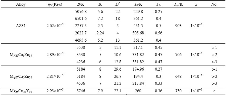
According to the cooling rates and thermal behavior experienced by the melt, amorphization or crystallization can occur during the cooling process. In order to get a better understanding of the behavior of TRC process and its cooling ability, thermal states under different casting conditions were computed with the thermal-flow coupling finite element method [3,8]. Figure 2 shows the schematic of TRC process, with melt supplied in two ways (i.e., center pouring mode shown in Fig. 2(a), and one side pouring mode shown in Fig. 2(b)). Because the ratio of the width to thickness is quite large, neglecting the side dams effect, a 2D finite element method (FEM) model is used. Considering the high speed feeding flow of liquid metal during the strip casting process, flow phenomenon in the molten pool is characterized as turbulent flow. And the following assumptions are made for steady-state simulations: there is no relative slip between the roll and strip, and heat transfer coefficient between them is constant (i.e., 10 and 3 kW/(m2��K)); surface temperature of the roller is 373 K; free surface of the melt is steady. Influences of melt level h, strip thickness ��, casting speed v (i.e., rotating speed) and pouring temperature Tp are considered in simulation. And considering geometric symmetry of the center pouring mode (i.e., Fig. 2(a)), half of the twin-roll casting model was employed.
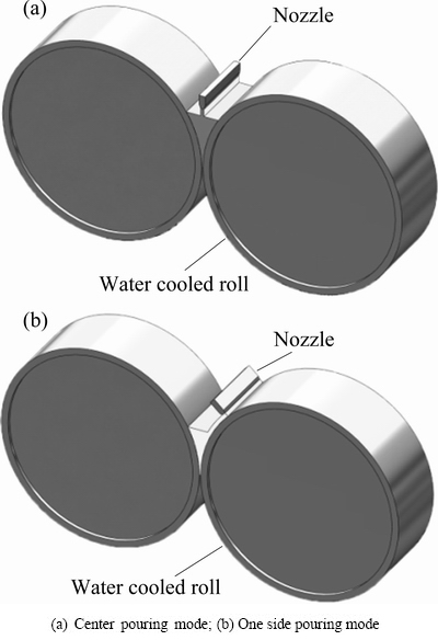
Fig. 2 Schematic of TRC process
Figure 3 illustrates the formation of the molten pool of the one side pouring mode. The process and dimensions are specified as follows: the melt is ejected on one roll using a nozzle, a strip shell forms along the roll surface, and the strip shell thickness is marked as d, which has the same value as nozzle. The metal shell of this part is cooled by the roll (the metal-roll contact side) and the atmosphere around it (the metal-air contact side). As it rolls down towards the nip, the metal shell contacts to the other side roll, and the height to the nip from this location is marked as h. The metal of this part is cooled by both of the rolls. In Fig. 3(a), h, which is marked as ha, depends on the metal shell thickness d and the roll gap. We can get a larger value of h with a smaller roll gap under a certain metal shell thickness d. In Fig. 3(b), it forms a molten liquid level. h which is marked as hb, is higher than ha under a same metal shell thickness and roll gap, and can change independently. With the effect of roll pressure (i.e., roll separating force), a thinner solidified strip forms and gets out from the roll nip. The total height of the molten pool is marked as L.
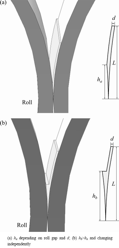
Fig. 3 Schematic of molten pool of one side pouring mode
4 Results and discussion
4.1 Estimation of critical cooling rates using CCT curves
From Eq. (1), the following equation can be deduced:
 (5)
(5)
When the ��0 is reduced to ��0r, Eq. (5) becomes the third term expressed within the bracket of Eq. (2). And we can see that, D*, ��0r and T0r are the main factors influencing the time of nucleation, with the variations of D* and T0r, t changes exponentially. D*, the fragility parameter of the supercooled liquid, relates to the nucleation and growth rate, and strong liquid behavior retards the formation of crystals kinetically and thermodynamically [19,22]. It was found that strong glass formers exhibit a very small T0 and a very high melt viscosity, while fragile glass formers show a T0 near Tg, as well as low melt viscosities [19]. The Mg-based alloy Mg65Cu25Y10 glass forming liquid in Busch��s study, in which D* is equal to 22.1, shows a strong liquid behavior.
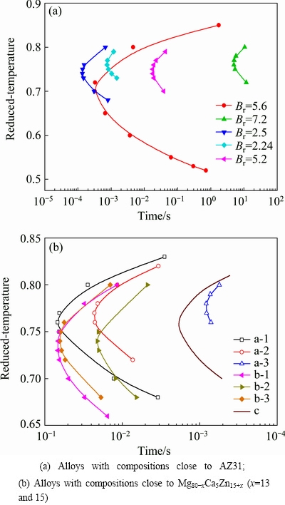
Fig. 4 Calculated time reduced-temperature transformation diagrams
The time reduced-temperature transformation diagrams of Mg-based alloys listed in Table 1 calculated by Eq. (2) are shown in Fig. 4. According to the above, alloys with compositions close to AZ31 could have small D* and T0 near Tg, and they may have ��C-curves�� located between the area of the two curves with Br values of 2.24 and 5.2, as shown in Fig. 4(a). The curve with Br of 2.24 has a ��nose time�� of 7.51��10-4 s at Tr of 0.76 and a critical cooling rate of 2.88��105 K/s. The curve with Br of 5.2 has a ��nose time�� of 1.78��10-2 s at Tr of 0.75 and a critical cooling rate of 1.27��104 K/s. Therefore, according to the time reduced-temperature transformation curve, a critical cooling rate of four orders of magnitude was estimated for these alloys.
Mg80-xCa5Zn15+x alloys (x=5 to 20) can be gotten under a cooling rate of 102 K/s or lower [23], and then we calculated the probable values of Br and T0r of these alloys. As shown in Fig. 4(b), a series of C-curves were calculated with parameters listed in Table 1 for the alloys with compositions close to Mg80-xCa5Zn15+x (x=13 and 15) alloys. For the alloys a-1, b-1 and b-3, they all have cooling rates of more than 1000 K/s. For alloy a-1, D* is 11.1, which is close to that of fragile liquid; for alloy b-1, D*=29.6 and for alloy b-3, D*=21.2, which are classified as strong liquids, with values of T0r all not large enough for making cooling rates get down to 102 K/s. From Fig. 4(b), it can be inferred that Mg80-xCa5Zn15+x alloys (x=5 to 20) have a value of D* from 10 to 25 and a relatively large T0r associates with small D*. And it was also found that, for the current series of alloys, the larger the D* is, the smaller the reduced nose temperature gets.
Figure 5 shows the calculated CCT curves of the alloy which has composition close to AZ31 with Br of 2.24 (Fig. 5 (a)) and Mg80-xCa5Zn15+x alloy with Br of 7 and Tm of 706 K (Fig. 5(b)). It can be found that the critical cooling rates of the two alloys are 7.99��104 and 1.7��102 K/s, respectively, and they are both lower than the values attained from time reduced-temperature transformation diagrams.
4.2 Influence of casting conditions on cooling rate
A rough estimation of the cooling ability of the vertical type twin-roll caster was made with the following equation:
 (6)
(6)
where RAVG is the average cooling rate in the casting pool, Tp and Tnip are, respectively, pouring temperature and temperature at the roll nip, h is the melt level of molten pool, and vc is the casting speed. Figure 6 shows the influences of different casting conditions on the average cooling rate for casting AZ31 alloy, where CP shows the center pouring mode, OSP shows the one side pouring mode. For the OSP mode, molten pool has a shape shown in Fig. 3(a). And here, we call L the melt level. From these results we can see that the average cooling rate under the CP mode is faster than that under the OSP mode.
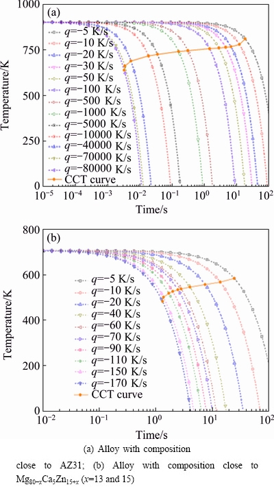
Fig. 5 Calculated CCT diagrams
Figure 6(a) shows the effect of melt level on RAVG under casting condition of pouring temperature of 953 K, casting speed of 0.5 m/s and strip thickness of 0.08 mm. We can see that with the melt level getting increased, the average cooling rate becomes smaller. At the melt level of 5 mm, it is too fast to solidify within such a short metal-roll contact distance that temperature at the roll nip is 856.57 K. When the strip thickness (i.e., nip width) is up to 0.2 and 0.5 mm with a melt level of 10 mm, as shown in Fig. 6(c), much more heat needs to be dissipated for the liquid to get fully solidified before it gets out of the rolls, and the casting process is prevented. On the other hand, with setting the melt level smaller and strip thickness thinner, a faster cooling rate could be attained and temperature at the roll nip is also appropriated. But, a fully amorphous metal would form before it passes the roll nip if the temperature is too low. This will cause a rolling block. From Fig. 6(b), we can see that the pouring temperature almost has no influence on the average cooling rate, but it can adjust the temperature at roll nip, i.e., a lower pouring temperature leads to a lower nip temperature. As a faster casting speed causes a faster cooling rate and a higher nip temperature (Fig. 6(d)), in order to attain a proper nip temperature under a faster casting speed, we can control the pouring temperature. However, if the nip temperature is high enough to make the temperature of the supercooled alloy still well above Tg before it passes the roll nip area, fully formation of amorphous structure might not be possible [3]. Therefore, the casting speed has an upper limit. Incidentally, the cooling rates under current conditions, as illustrated in Figs. 6(b) and (d), are all in the order of magnitude of 104 K/s, which has a same level with the calculated critical cooling rate.
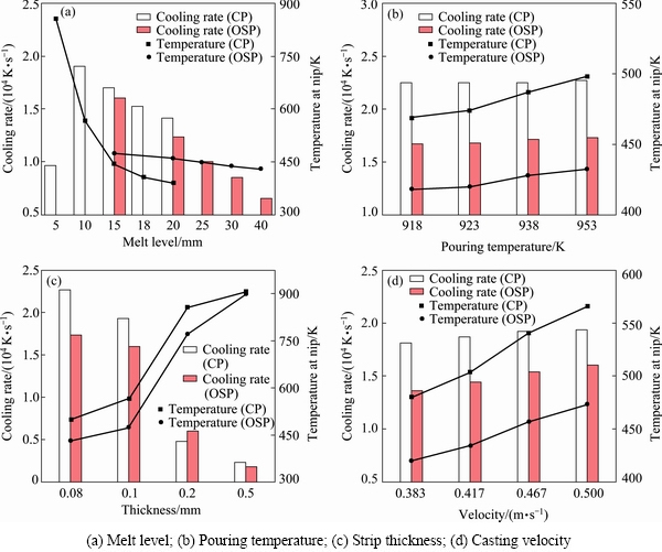
Fig. 6 Effects of casting conditions on cooling rate
Based on the continuum theory, a special form of material (or material-time) derivative for any physical quantity �� under motion status in Eulerian coordinate has been proposed by INOUE et al [24]:
 (7)
(7)
where v is the velocity vector of material point, and x is a vector representing a space-fixed coordinate system.
According to the theory above, in order to analyze the thermal phenomenon of the molten pool, cooling rate R(T) at the center of pool is calculated by
 (8)
(8)
where T is the temperature at pool center, y is the location in the pool height direction, �� is the velocity of the local melt, and t is the time. Temperature distributions of the molten pool in the center pouring mode are shown in Fig. 7. Figure 7(a) shows the temperature distribution of AZ31 alloy (with pouring temperature of 918 K, casting speed of 30 m/min, strip thickness of 0.08 mm, melt level of 10 mm) and illustrates the origin of coordinates used for calculation, point O is the center of the roll nip. Line D shows the isothermal line of 677.25 K (Tr=0.75), with a cooling rate of 3.37��104 K/s calculated by Eq. (8), which has the same order of magnitude with the calculated critical cooling rate. Fig. 7(b) shows the temperature distribution of Mg80-xCa5Zn15+x (x=5 to 20) alloys with pouring temperature of 736 K, casting speed of 3 m/min, strip thickness of 0.1 mm and melt level of 20 mm. It has a cooling rate of 2 to 3 orders of magnitude at the ��nose temperature��. We can find that the typical wedge shaped temperature profile often observed in TRC is completely absent. It may be because the physical properties of metallic glasses are different from the parameters used in normal TRC simulation. And the geometry of the casting pool is also different (e.g., the roll gap is very small), as well as the rotation speed of the rolls.
In order to find out the characteristics of the pool metals in two pouring modes (i.e., center pouring mode and one side pouring mode) mentioned above, temperature distributions of the molten pools during casting AZ31 alloy were compared and cooling rates at each temperature were also calculated (Fig. 8). Figure 8(a) shows the results in the center pouring mode and the following casting conditions: pouring temperature of 918 K, casting speed of 30 m/min, strip thickness of 0.1 mm and melt level of 11.63 mm, with the same value as ha shown in Fig. 3(a). Figure 8(b) shows the results in the one side pouring mode and has the same pouring temperature, casting speed and strip thickness as the center pouring mode. The value of h is 11.63 mm and L is 15 mm (Fig. 3(a)), and we call this one side pouring mode mode-I. From these results, we can see that, around the nose temperature of AZ31 alloy calculated in Section 4.1, cooling rates of four orders of magnitude could be attained in both of the two pouring modes. But in the one side pouring mode-I, we can get a faster cooling rate than that under the center pouring one. On the other side, from the point of view of nip temperature, we can get a lower temperature at the roll nip using the one side pouring mode-I.
In the twin-roll casting process, one of the most important factors is the melt level L, and its influence on the temperature distribution is shown in Fig. 9. And we call the model used in Fig. 9(b) one side pouring mode-II. Casting conditions are as follows: pouring temperature of 918 K, casting speed of 30 m/min, and strip thickness of 0.1 mm, and melt levels in the two pouring modes are listed in Table 2. For the one side pouring mode-II, it has a strip shell thickness of 1 mm (i.e., d=1 mm).
Figures 9(a) and (b) show the cooling rates along the center line of the molten pools. We can get a faster cooling rate with the CP mode when the melt level is not very high (L=15 mm). However, when the melt level gets higher, the melt-roll contact area becomes larger, and the melt is cooled down directly to a low temperature, which would cause a rolling block. And one of the solution is to adopt the OSP method to improve the temperature distribution.
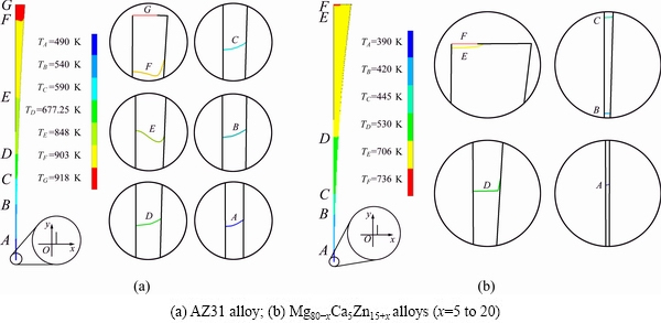
Fig. 7 Temperature distributions and isotherms of center pouring mode

Fig. 8 Cooling rates and temperature distributions in two pouring modes

Fig. 9 Cooling rates and temperature distributions
Table 2 Influence of melt level on cooling rates and nip temperatures under two pouring modes
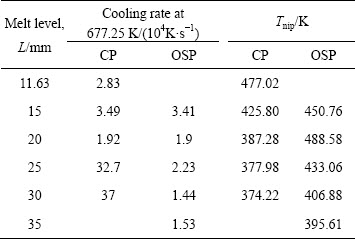
It can be seen from Table 2 that, for a certain melt level, we can get a faster cooling rate using the CP mode, and also nip temperature is lower than that in OSP mode. On the other hand, however, it is not expected to get a temperature too low at the roll nip due to the special properties of metallic glass. Fully solidified metallic
glass deforms hardly due to its very high strength. Therefore, we can use the OSP mode to adjust the strip temperature at nip for a certain melt level.
Figures 9(c) and (d) show the temperature distributions of the molten pools in the two pouring modes. The high temperature region in CP mode reduces rapidly compared with OSP mode as melt level gets higher. When the melt level is 30 mm, as shown in Fig. 9(c), mostly of the pool region is at low temperature, and this is not good for the casting process. In this situation, it is better to choose the OSP mode.
5 Conclusions
1) The time reduce-temperature transformation diagrams for Mg-based alloys were calculated using an empirical equation. CCT diagrams were also calculated using the additivity rule. The critical cooling rate gotten by time reduce-temperature transformation diagram is faster than that gotten by CCT diagram.
2) In the VTRC process, a faster cooling rate can be attained using the center pouring mode compared with the one side pouring mode when it forms a metal level in the molten poll because melt heat of the former is extracted more efficiently.
3) In the situation of a molten pool with no formation of metal level (e.g., one side pouring mode-I), a faster cooling rate could be attained using the one side pouring mode.
4) Changing the casting conditions or adopting the one side pouring mode could improve the temperature distribution of the pool metal, and the rolling block can be avoided. Cooling rates with 4 orders of magnitude by the VTRC process under the current conditions can be attained, which shows that VTRC technique has a potential ability in continuous fabrication of Mg-based bulk amorphous alloys in sheet form.
Acknowledgements
This research receives ongoing support from the High-Tech Research Center and Nano-technology Project at Saitama Institute of Technology, Japan.
References
[1] NARASIMHAN M C. Continuous casting method for metallic strips: US Patent, 4142571 [P]. 1979-03-06.
[2] ANDREAS A K, J RG F L, FLORIAN H D T. Rapid solidification and bulk metallic glasses-processing and properties [M]. Boca Raton: CRC Press, 2007.
[3] LEE J G, PARK S S, LEE S B, CHUNG H T, KIM N J. Sheet fabrication of bulk amorphous alloys by twin-roll strip casting [J]. Scripta Materialia, 2005, 53: 693-697.
[4] LEE J G, LEE H, OH Y S, LEE S, KIM N J. Continuous fabrication of bulk amorphous alloy sheets by twin-roll strip casting [J]. Intermetallics, 2006, 14: 987-993.
[5] URATA A, NISHIYAMA N, AMIYA K, INOUE A. Continuous casting of thick Fe-base glassy plates by twin-roller melt-spinning [J]. Materials Science and Engineering A, 2007, 449-451: 269-272.
[6] EAST D R, KELLAM M, GIBSON M A, SEEBER A, LIANG D, NIE J F. Amorphous magnesium sheet produced by twin roll casting [J]. Materials Science Forum, 2010, 654-656: 1078-1081.
[7] DING Pei-dao, PAN Fu-sheng, JIANG Bin, WANG Jian, LI Hua-lun, WU Jiang-cai, XU Yue-wang, WEN Yu. Twin-roll strip casting of magnesium alloys in China [J]. Transactions of Nonferrous Metals Society of China, 2008, 18(S): s7-s11.
[8] HU Xiao-dong, JU Dong-ying, ZHAO Hong-yang. Thermal flow simulation of twin-roll casting magnesium alloy [J]. Journal of Shanghai Jiaotong University (Sci), 2012, 17: 479-483.
[9] JU Dong-ying, HU Xiao-dong. Effect of casting parameters and deformation on microstructure evolution of twin-roll casting magnesium alloy AZ31 [J]. Transactions of Nonferrous Metals Society of China, 2006, 16(S): s874-s877.
[10] LEE Y S, KIM W K, JO D A, LIM C Y, KIM H W. Recrystallization behavior of cold rolled Al-Zn-Mg-Cu fabricated by twin roll casting [J]. Transactions of Nonferrous Metals Society of China, 2014, 24: 2226-2231.
[11] DUGGAN G, BROWNE D J. Modelling and simulation of twin-roll casting of bulk metallic glasses [J]. Trans Indian Inst Met, 2009, 62: 417-421.
[12] CAO J D, KIRKLAND N T, LAWS K J, BIRBILIS N, FERRY M. Ca-Mg-Zn bulk metallic glasses as bioresorbable metals [J]. Acta Biomaterialia, 2012, 8: 2375-2383.
[13] CHEN H S. Glassy metals [J]. Reports on Progress in Physics, 1980, 43: 353-432.
[14] LEE S B, KIM N J. Kinetics of crystallization in continuously cooled BMG [J]. Materials Science and Engineering A, 2005, 404: 153-158.
[15] LFFLER J F. Bulk metallic glasses [J]. Intermetallics, 2003, 11: 529-540.
[16] TAKEUCHI A, INOUE A. Evaluation of glass-forming ability for metallic glasses from time-reduced temperature-transformation diagram [J]. Materials Transactions, 2001, 42: 2374-2381.
[17] UHLMANN D R. A kinetic treatment of glass formation [J]. Journal of Non-crystalline Solids, 1972, 7: 337-348.
[18] TAKEUCHI A, INOUE A. Quantitative evaluation of critical cooling rate for metallic glasses [J]. Materials Science and Engineering A, 2001, 304-306: 446-451.
[19] BUSCH R, LIU W, JOHNSON W L. Thermodynamics and kinetics of the Mg65Cu25Y10 bulk metallic glass forming liquid [J]. Journal of Applied Physics, 1998, 83: 4134-4141.
[20] XU Kai, WANG Yan, LI Jin-feng, LI Qiang. Critical cooling rate for the glass formation of ferromagnetic Fe80P13C7 alloy [J]. Acta Metallurgica Sinica (English Letters), 2013, 26: 56-62.
[21] UMEMOTO M, HORIUCHI K, TAMURA I. Pearlite transformation during continuous cooling and its relation to isothermal transformation [J]. Transactions of the Iron and Steel Institute of Japan, 1983, 23: 690-695.
[22] BUSCH R, MASUHR A, JOHNSON W L. Thermodynamics and kinetics of Zr-Ti-Cu-Ni-Be bulk metallic glass forming liquids [J]. Materials Science and Engineering A, 2001, 304-306: 97-102.
[23] GU X F, SHIFLET G J, GUO F Q, POON S J. Mg-Ca-Zn bulk metallic glasses with high strength and significant ductility [J]. Journal of Materials Research, 2005, 20: 1935-1938.
[24] INOUE T, JU D Y, YOSIHARA N. Temperature and viscoplastic stresses during vertical semi-continuous direct chill casting of aluminum alloy [M]. Heidelberg: Springer, 1989.
��ʽ˫���������������������ٽ���ȴ���ʼ�����������ģ��
�����1����Ӣ2,3���� ѩ3
1. Graduate School of Saitama Institute of Technology, Fusaiji 1690, Fukaya, Saitama 369-0293, Japan;
2. Department of Material Science and Engineering, Saitama Institute of Technology, Fusaiji 1690, Fukaya, Saitama 369-0293, Japan;
3. �����Ƽ���ѧ ������ұ��ѧԺ����ɽ 114051
ժ Ҫ��ͨ�������γɽ���������������ȴת��(CCT)ͼ�ó����ٽ���ȴ���ʡ�����ʽ˫������(VTRC)�������۳ؽ����¶ȳ�������ֵģ�⣬�������ͬ���������µ���ȴ���ʡ�ͨ����������ȴ���ʽ��бȽϣ����۲���VTRC����������������Ŀ����Ժ�����������ȴ���ʵ�Ӱ�졣 ���������ͨ��VTRC��������þ��������������ȴ���ʿɴﵽ3��4����������������CCTͼ����õ����ٽ���ȴ���ʡ����õ��ཽע��ʽ���Ը����۳��ڽ������¶ȷֲ���VTRC���վ������õ����������������������������
�ؼ��ʣ������������ٽ���ȴ���ʣ�˫��������ģ��
(Edited by Wei-ping CHEN)
Corresponding author: Dong-ying JU; Tel: +81-48-5956826; Fax: +81-48-5855928; E-mail: dyju@sit.ac.jp
DOI: 10.1016/S1003-6326(17)60267-X
Abstract: Critical cooling rates for producing metallic glasses were evaluated based on a calculated continuous cooling transformation (CCT) diagram. Temperature distributions of the melt in molten pool in the vertical type twin-roll casting (VTRC) process of metallic glasses were simulated, and cooling rates under different casting conditions were calculated with the simulated results. By comparing the results obtained by CCT diagrams and simulation, the possibility of producing metallic glasses by the VTRC method and influences of casting conditions on cooling rate were discussed. The results reveal that cooling rate with 3 or 4 orders of magnitude by the VTRC process can be attained in producing Mg-based metallic glasses, which is faster than the critical cooling rate calculated by the CCT diagram. One side pouring mode can improve the temperature distributions of casting pool. VTRC process has a good ability in continuous casting metallic glassy thin strips.
