
J. Cent. South Univ. (2016) 23: 2443-2452
DOI: 10.1007/s11771-016-3303-x

Tri-level programming model for combined urban traffic signal control and traffic flow guidance
SUN Zhi-yuan(����Դ)1, 2, LU Hua-pu(½����)1, QU Wen-cong(���Ŵ�)1
1. Institute of Transportation Engineering, Tsinghua University, Beijing 100084, China;
2. College of Metropolitan Transportation, Beijing University of Technology, Beijing 100124, China
 Central South University Press and Springer-Verlag Berlin Heidelberg 2016
Abstract:
In order to balance the temporal-spatial distribution of urban traffic flow, a model is established for combined urban traffic signal control and traffic flow guidance. With consideration of the wide use of fixed signal control at intersections, traffic assignment under traffic flow guidance, and dynamic characteristics of urban traffic management, a tri-level programming model is presented. To reflect the impact of intersection delay on traffic assignment, the lower level model is set as a modified user equilibrium model. The middle level model, which contains several definitional constraints for different phase modes, is built for the traffic signal control optimization. To solve the problem of tide lane management, the upper level model is built up based on nonlinear 0-1 integer programming. A heuristic iterative optimization algorithm (HIOA) is set up to solve the tri-level programming model. The lower level model is solved by method of successive averages (MSA), the middle level model is solved by non-dominated sorting genetic algorithm II (NSGA II), and the upper level model is solved by genetic algorithm (GA). A case study is raised to show the efficiency and applicability of the proposed modelling and computing method.
Key words:
traffic engineering; traffic signal control; traffic flow guidance; tri-level programming model��
1 Introduction
Urban traffic control system (UTCS) and urban traffic flow guidance system (UTFGS) are two important subsystems of intelligent transportation systems (ITS). UTCS adjusts compulsorily traffic flow from the perspective of temporal distribution. Since the Gas Traffic Light was born in London in December 10, 1868, after about 100 years of development, the current representative applications of UTCS include SCATS (Australia) [1], SCOOT (UK) [2] and TRANSYT (UK) [3]. UTFGS proposes guidance service on traffic flow from the perspective of spatial distribution. The current representative applications of UTFGS, the research of which was started in the 1960s, include VICS (Japan) [4] and ADVANCE (USA) [5]. Since ALLSOP [6] combined researches of traffic control and traffic assignment together, the co-theory of UTCS and UTFGS has gradually become a hot spot. The domestic research was started in the 1990s.
After almost 40 years of research, the co-theory of UTCS and UTFGS presents the trend of multi-mode development: independent operation mode [7], UTCS preferred mode [8], UTFGS preferred mode [9], iterative optimization mode [10] and global optimization mode [11]. Influenced by basic data, traffic conditions and other factors, different modes have different applicability. In recent years, the research focuses on the last two modes. CHEN and HU [12] established a bi-level programming model for combined UTCS and UTFGS, in which the upper level is the induction control model, and the lower level is the DynaTAIWAN model. A unified framework of UTFGS and UTCS was established by AZIZ and UKKUSURI [13] based on cellular transmission model, considering intersection delay, travel time and green time loss. MENEGUZZER [14] put forward two discrete-time dynamic process models for combined UTCS and UTFGS. A simulation based framework was proposed by LI et al [15] to solve the cooperation problems of VMS travel guidance and traffic signal control. Research on the combined UTCS and UTFGS based on neural network was conducted by FU et al [16].
By research on the construction and operation of ITS in China, some facts are found. 1) Fixed control for different time periods is still widely used at the intersections, because of the factors like that loop detectors of UTCS are easy to be damaged, and that several brands of signal control machines are often installed in the same city. 2) As tidal phenomenon occurs frequently in urban trunk road due to the separation of living and working, tide lane management (TLM) has a significant meaning to reflect the dynamic characteristics of urban traffic. 3) The travelers can fully understand the traffic state based on widely spread traffic guidance information.
However, in comparison with the research status of combined UTCS and UTFGS, some problems are found. 1) Although some studies have considered fixed control, the model framework has neglected the influence of phase design of intersections and the delay of different directions on traffic assignment. Thus, it affects the accuracy of traffic assignment. 2) Although some researches have applied induction control, the model framework has neglected the consideration of dynamic data acquisition problems. Then, it is hard to achieve expected results in case of data missing in practice. 3) In addition, little consideration of TLM is given in combined UTCS and UTFGS, which affects the efficiency of traffic management.
Therefore, with consideration of these facts and problems, this work establishes a new model for the combined UTCS and UTFGS. The framework of combined UTCS and UTFGS is put forward. Then, the tri-level programming model is present based on the proposed framework. A heuristic iterative optimization algorithm is built. A case study is carried out to verify the applicability and reliability of the model and algorithm. Finally, conclusions are drawn.
2 Framework of combined UTCS and UTFGS
Since UTCS in this work applies fixed control for different time periods, it is a static system during a certain time period. Considering traffic safety, engineering facilities and other factors, TLM is not suitable for real-time variation. Its dynamic management features are reflected in the implement of different TLM schemes during different time periods. Therefore, TLM is also a static system for a certain time period. UTFGS can be sorted into two classes: pre-guidance before a time period and real-time guidance during the time period. For a certain time period, the pre-guidance is a static system, while real-time guidance is a dynamic system.
The optimization objective of UTCS is the maximum of traffic efficiency of intersection, which can be measured by delay and saturation. UTCS optimization problem can be expressed as
 (1)
(1)
where JA(��) is the performance index (PI) function of UTCS, taken together delay d and saturation ��; JC(��) can be further expressed as fC(��), a function of green ratio ��, traffic volume x, number of lanes l. In this optimization model, x and l are known parameters, and �� is the decision variable.
The optimization objective of UTFGS is the maximum of user��s benefit or system efficiency, which can be measured by travel time. UTFGS optimization problem can be expressed as
 (2)
(2)
where JA(��) is the PI function of UTFGS, considering system travel time T. JA(��) can be further expressed as fA(��), a function of travel time t and traffic volume x. t is a function of ��, x, and l, therefore fA(��) will be transformed into fA��(��). In this optimization model, �� and l are known parameters, and x is the decision variable.
The optimization objective of TLM is the maximum of traffic efficiency of road network, which can be measured by travel time. TLM optimization problem can be expressed as
 (3)
(3)
where JT(��) is the PI function of TLM, considering system travel time T. JT(��) can be further expressed as fT(��), a function of ��, x and l. In this optimization model, �� and x are known parameters, and l is the decision variable.
UTCS, UTFGS and TLM are connected closely. If the output of a system is changed, the output of the other two systems will also be changed. Besides, because the optimization objectives of these three systems are different, it is difficult to establish a single optimization objective model. Even if a relatively effective PI function can be found, it is too difficult to solve the model because of the great number of the decision variables. Thus, the combined UTCS and UTFGS considered TLM is a complex decision-making process. To solve this problem, the following basic assumptions are made.
1) Considering the static and dynamic characteristics of UTCS, UTFGS and TLM, combined UTCS and UTFGS should be divided into two stages: in the first stage, intersection fixed control, traffic pre- guidance and tide lane scheme are determined based on the traffic demand in the research time period; in the second stage, the dynamic traffic guidance scheme is designed based on the real-time traffic flow, intersection fixed control and tide lane scheme. However, the thought of collaborative optimization is only reflected in the first stage. Therefore, this work focuses on the first stage.
2) The traffic demand, obtained by other methods, is a known parameter in this work. Moreover, it has little changes during a certain time period.
3) UTFGS releases the traffic information to travelers, so that they totally understand the traffic state of road network. The travelers obey the guidance of UTFGS, and choose the path with the shortest travel time. Therefore, the optimization of UTFGS is expressed by user equilibrium model considering intersection delay.
Based on these assumptions, a tri-level programming model is established to study the combined UTCS and UTFGS considered TLM: the lower level model is a mortified user equilibrium model; the middle level model is a signal control optimization model; the upper level model is a tide lane optimization model. The model framework is shown in Fig. 1.
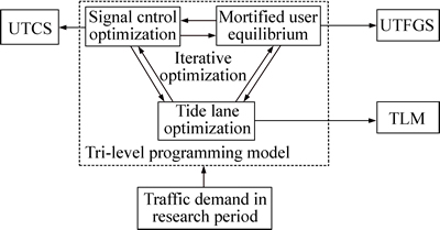
Fig. 1 Model framework
3 Tri-level programming model
3.1 Lower level model
The lower level model is proposed to realize the optimization of UTFGS. Virtual section is designed to reflect the impact of intersection delay on traffic assignment. When a traveler passes through section to intersection, there are four choices: go through, turn around, turn left, and turn right. Due to the relatively small flow, turning around is not considered in this work. The design of virtual section is shown in Fig. 2.
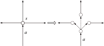
Fig. 2 Design of virtual section
A1 is the set of virtual sections; A2 is the set of actual sections; ta(xa) is the travel time function of section a. If  ta(xa) is the delay of intersection lane group corresponding to virtual section a, which is calculated by Eq. (11). If
  ta(xa) is usually BPR (Bureau of Public Road) function [17]:
 (4)
(4)
where  is the free travel time of section a; xa is the traffic volume of section a; Ca is the capacity of section a. ��1 and ��2 are the coefficients.
For 
 is the strictly monotone increasing function of xa. User equilibrium assignment model considering intersection delay can be expressed as
 (5)
(5)
s.t.
 (6)
(6)
 (7)
(7)
 (8)
(8)
 (9)
(9)
where is the traffic volume on path k between origin r and destination s; Krs is the set of all paths between origin r and destination s; qrs is the traffic volume between origin r and destination s; R is the set of origin r; S is the set of destination s;
  is a 0-1 variable. If section a is on path k between origin r and destination s, then
  ; otherwise,
3.2 Middle level model
The middle level model is built to optimize UTCS. Since Eq. (1) belongs to traditional method and has some defects, it is improved based on multi-objective optimization programming (MOP) in this work. And, some definition constraints for different phase modes are embedded in the model.
3.2.1 Objective function
Considering the characteristics of phase mode, the decision variables of UTCS optimization problem are changed, and the PI function is improved as
 (10)
(10)
where g is the green time. g is the decision variable in this optimization model.
There are many methods to calculate the delay and saturation of intersection. The Webster method [18] is used as

 (11)
(11)
 (12)
(12)
 (13)
(13)
 (14)
(14)
 (15)
(15)
where  is the delay of lane group i of intersection j;
  is the green ratio of lane group i of intersection j; Cj is the cycle length of intersection j;
 is the saturation of lane group i of intersection j;
  is the traffic volume of lane group i of intersection j;
  is the capacity of lane group i of intersection j;
  is the saturation flow rate of lane group i of intersection j;
  is the effective green time of lane group i of intersection j;
  is the green time of lane group i of intersection j; ty is the yellow time; ts is the loss time.
Based on the delay and saturation of each lane group, the overall index of the intersection is calculated by
 (16)
(16)
 (17)
(17)
where  is the average vehicle delay of section j; ��j is the generalized saturation of intersection j.
In order to determine the expression of the PI function, its validity should be proved firstly. A MOP model considering delay and saturation is established as
 (18)
(18)
Based on NSGA II, Pareto solution set can be calculated as shown in Fig. 3.
An approximate linear negative correlation is found between delay and saturation. That is, these two objectives are in conflict with each other. Therefore, it is a group of effective optimization objectives, which verifies the validity of Eq. (18).
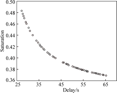
Fig. 3 Relationship between delay and saturation
Then, the corresponding relationship among delay, saturation and traffic state is studied. Therefore, the weight of delay and saturation in the PI function can be determined. Furthermore, an optimal solution will be selected from the Pareto solution set. According to the standard of Level of Service (LOS) for intersection in China [19], when the delay is greater than 80 s, the traffic flow is super saturated, and is often in a blocked state. Thus, a delay of 80 s corresponds to the saturation of 1.0. When delay and saturation are equally important, the PI function could be expressed as
 (19)
(19)
3.2.2 Constraints
General constraints for UTCS include: cycle length constraint and minimum green time constraint.
 (20)
(20)
 (21)
(21)
where Cmin is the minimum cycle length; Cmax is the maximum cycle; gmin is the minimum green time.
Commonly used phase modes include two-phase, three-phase and four-phase, according to the number of phases. They can also be divided into considering and not considering the overlapping phase modes. This work takes the four-phase mode considering overlapping phase as an example, and the form of definition constraint is expressed as
 (22)
(22)
where tr is the all red time. The semantic coding of approach and group is shown in Fig. 4.
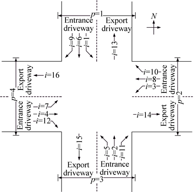
Fig. 4 Semantic coding of approach and group
3.3 Upper level model
The upper model is put forward to realize the optimization of TLM. Total travel time is composed of travel time in actual section and intersection delay (travel time in virtual section). TLM optimization problem can be further expressed as
 (23)
(23)
Constraints include the limitation number of lanes for each section and intersection, the balance of lanes for intersection, and the integer constraints of decision variables [20].
The TLM optimization model (23), which is an ideal model, belongs to nonlinear integer programming problem. Hence, it is difficult to be solved. In addition, the model does not consider the problems of traffic engineering design for tide lanes. And, it is hard for the constraints to cover all the problems in practice, which makes the feasible domain of the model rather large. Therefore, a simplified model is needed.
A two-way road with six lanes (as shown in Fig. 5), which is a common form of urban trunk road, is taken as an example.
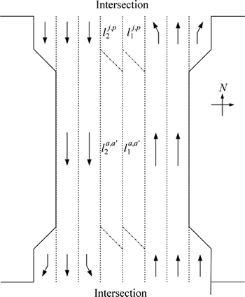
Fig. 5 Schematic diagram of tide lane
The basic characteristics are shown as follows.
1) Due to lane widening, a lane is added at both entrance driveway and export driveway.
2) For the two-way road with six lanes, only two lanes are allowed to be tide lane. Thus, two 0-1 variables  and
and  are introduced to indicate the tide lanes on section a and a��: on north-south sections, 1 indicates that the direction is south to north, and 0 indicates that the direction is north to south; on east-west sections, 1 indicates that the direction is east to west, and 0 indicates that the direction is west to east. Besides, say la signifies the number of lane of section a,
  signifies the number of lane of section a��.
3) In order to ensure the straight-going, right-turn and left-turn traffic flow, the entrance driveway needs at least one straight-going lane, one right turn lane, and one left turn lane. In addition, the export driveway needs at least three lanes to ensure that the vehicles could leave the intersection.
4) With the help of intersection channelization, the entrance driveway can take up a lane of the export driveway. According to the value of and possibilities of intersection channelization are discussed:
�� If 
 then
then 
 It is not suitable for the entrance driveway to take up a lane of the export driveway, and two lanes at this entrance driveway are possible for the decision of through or right turn.
�� If 
 then
then 
 It is possible for the entrance driveway to take up a lane of the export driveway, and one lane is possible for the decision of through or right turn.
�� If  or then la=3,
  It is not suitable for the entrance driveway to take up a lane of the export driveway, and two lanes are possible for the decision of through or right turn.
Therefore, another two 0-1 variables  and
and  may be introduced to express tide lanes at the entrance driveway, say 1 signifies through lane, 0 signifies left turn lane. Besides, say
  signifies the number of left turn lane,
  signifies the number of through lane.
5) In general,  and
and  are four 0-1 variables for tide lane decision. 0-1 variable makes the decision process simpler, but loses its meaning in some cases. For example,
��For  this form of lane sequence is rare in reality, however the form that la=3 and
  exists.
�� For 
 this form of lane sequence is rare in reality; however, the form that
  and
and  exists.
Therefore, after obtaining an optimal solution, the value of 

 and
and  should be calculated, which is the management scheme of TLM.
Following formulas are introduced to calculate  la and


 (24)
(24)

 (25)
(25)
 (26)
(26)
 (27)
(27)
In summary, the objective function of the simplified model is Eq. (23), the definitional constraints of which are shown in Eqs. (24)-(27).  and are decision variables in this optimization model.
4 Solution algorithms
4.1 Heuristic iterative optimization algorithm
The proposed tri-level programming model is NP-hard. A heuristic iterative optimization algorithm is designed as follows:
Step 0: Initialization: Set iteration number n1=0, ignore the influence of virtual section and tide lane.
Step 1: Solution of the lower level model: Apply MSA to solve the lower level model, and obtain the traffic flow  (
( ) in the iteration n1.
Step 2: Solution of the middle level model: Apply on NSGA II to solve the middle level model, and obtain the signal timing scheme  for each intersection in the iteration n1.
Step 3: Solution of the upper level model: Apply GA to solve the upper level model, obtain the lane number  () of each section in the iteration n1.
Step 4: Iterative computation: Set  and return to Step 1.
Step 5: Convergence judgment: If the difference of traffic flow between two adjacent iterations is small enough, then stop and record the best solution; otherwise continue the iteration. The mean absolute percentage error (MAPE) is used as the convergence criterion.
 (28)
(28)
where m is the total number of sections ().
4.2 Algorithm for lower level model
The lower level model is a mortified UE model. MSA is applied to resolve the model:
Step 0: Set iteration number 
 do 0-1 assignment according to the free travel time of each section to get an initial solution xa.
Step 1: Set  update the travel time of each section
Step 2: Do 0-1 assignment according to the travel time of each section  to obtain additional volume
Step 3: Update traffic flow 

Step 4: Convergence judgment: if the difference of traffic flow between two adjacent iterations is not big, then stop and record the final result of assignment; otherwise go to Step 1. MAPE is used as the convergence criterion.
4.3 Algorithm for middle level model
The solution of the middle level model is divided into two stages. Firstly, Pareto solution set should be calculated, and then the solution that meets the requirements is picked. The NSGA II is proposed to solve the MOP model [21]. In this work, the multi-object compatibility algorithm based on NSGA II is presented to solve the middle level model.
Step 1: Initialization, determine the individual size, population size, mutation probability, maximum evolutionary algebra. Randomly generate initial population, and set the evolutionary algebra n3=0.
Step 2: Carry out the crossover mutation operation to the population  to obtain the sub population
  and calculate the objective function.
Step 3: If the termination condition is satisfied, go to Step 9, otherwise go to the next step.
Step 4: A new species group is obtained by combining the parent population and the offspring population 
Step 5: Execute fast non dominated sorting algorithm, get the non-domination of the population 
Step 6: Establish new population 
Step 7: The selection mechanism based on crowding distance is used to select the parent individual from population  Perform the crossover and mutation operations, to generate the offspring population, and calculate the objective function value.
Step 8: Set  and return to Step 3.
Step 9: Obtain the Pareto solution set, and keep the offspring population 
Step 10: Solve Eq. (19) and obtain a solution from the Pareto solution set.
4.4 Algorithm for upper level model
The upper level model belongs to nonlinear 0-1 integer programming, and its computational complexity is exponential. GA is used to solve the problem. The main factors of GA are designed as follows.
1) Initiation: 0-1 coding is designed for the decision variables in the model, with the individual size same as the number of decision variables. The population size, mutation probability, maximum genetic algebra, etc. are set up here.
2) Fitness evaluation: for minimization problem, the reciprocal of objective function is used as the fitness value of individual.
3) Selection operation: roulette wheel selection is adopted for the selection operation.
4) Cross operation: single-point crossover is adopted for cross operation.
5) Mutation operation: uniform mutation is adopted for the mutation operation, meaning every individual in current population has a chance to mutate.
6) Stopping criteria: GA algorithm will be end after the maximum genetic algebra is reached.
5 Numerical example
5.1 Data
As shown in Fig. 6, a road network with 12 nodes is taken as the numerical example. The road network includes 24 sections (each section has two fixed lanes and one tide lane), 8 origin or destination points (i=1, 2, ��, 8), 64 OD pairs (r=1, 2, ��, 8, s=1, 2, ��, 8), and 4 main intersections (j=9, 10, 11, 12).
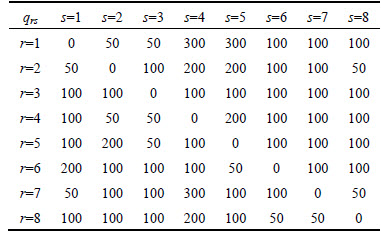
The traffic demand in the research time period is listed in Table 1.
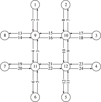
Fig. 6 Road network for numerical example
Table 1 Traffic demand in research time period (pcu/h)
5.2 Calculation process
1) Design of virtual section
The design of virtual section is shown in Fig. 7. Nodes 13-20 and the 12 sections between them are the virtualization of intersection 9. Nodes 21-28 and the 12 sections between them are the virtualization of intersection 10. Nodes 29-36 and the 12 sections between them are the virtualization of intersection 11. Nodes 37-44 and the 12 sections between them are the virtualization of intersection 12.
2) Initialization
Set n1=0. Ignore the influence of virtual section and tide lane, namely each section has three lanes and each intersection has one left turn lane, two through lane and one right turn lane.
3) Lower level model initialization
As shown in Fig. 8, after 52 iterations, the model is converged to  As some sections have no flow during the first two iterations, the value of MAPE is therefore meaningless.
4) Middle level model initialization
Prato solution set for 4 intersections is shown in Fig. 9.

Fig. 7 Design of virtual section for numerical example
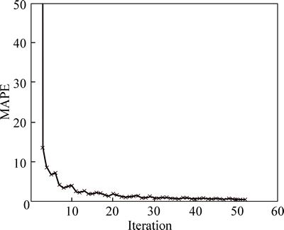
Fig. 8 Initialization of lower level model

Fig. 9 Initialization of middle level model:
5) Upper level model initialization
As shown in Fig. 10, the optimal solution is get within the maximum genetic algebra.
6) Iterative optimization
When n1=3,  then the solution of the tri-level programming model is finished and the optimal solution is obtained. Iterative optimization is shown in Fig. 11.
5.3 Results and discussions
Through calculation process, the scheme of UTCS, UTFGS, and TLM are obtained, as listed in Tables 2-4.
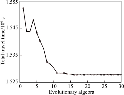
Fig. 10 Initialization of upper level model
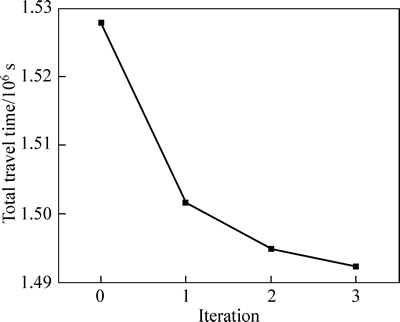
Fig. 11 Iterative optimization
Figure 11 reflects the characteristics of iterative optimization.
1) When n1=0, the output of the tri-level programming model represents the independent operation of UTCS, UTFGS and TLM. The total travel time is the longest.
2) With the increasing of iteration, the tri-level programming model converges gradually, and the total travel time reduces gradually. It shows that the traffic efficiency is improved by the proposed model.
3) In addition, MAPE is used as the convergence criterion in this work. If the convergence criterion is switched to the maximum number of iteration, the total travel time will be further reduced according to the trend shown in Fig. 11.
Table 2 Number of lane of each lane group
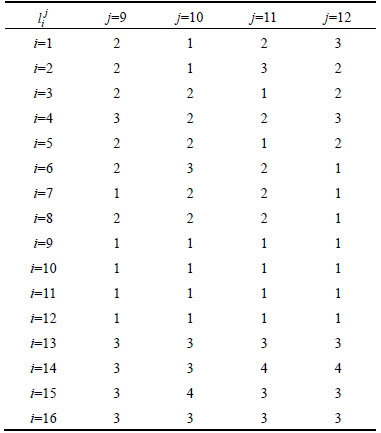
Table 3 Green time (s) of each lane group
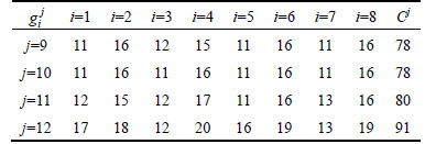
Table 4 Number of lane of each section

6 Conclusions
1) A tri-level programming model is put forward for the combined UTCS and UTFG. The lower level model is a mortified UE model, which considers the effect of intersection delay on traffic assignment; the middle level model is a signal control optimization model, which considers different phase modes; the upper level model is a tide lane optimization model, which belongs to nonlinear 0-1 integer programming.
2) A heuristic iterative optimization algorithm (HIOA) is developed to solve the proposed model. The lower level model is solved by method of successive averages (MSA); the middle level model is solved by non-dominated sorting genetic algorithm (NSGA II); the upper level model is solved by Genetic Algorithm (GA). The model and algorithm are verified by numerical examples.
3) On the basis of this study, the second stage of combined UTCS and UTFGS should be studied. In order to meet the dynamic changes of the traffic demand, a dynamic traffic guidance scheme should be carried out, according to the dynamic traffic flow data. In addition, the travel behavior under traffic guidance, the combined UTCS and UTFGS under signal priority control or green wave control, should be discussed in future study.
References
[1] SIMS A G, DOBINSON K W. The Sydney coordinated adaptive traffic (SCAT) system philosophy and benefits [J]. IEEE Transactions on Vehicular Technology, 1980, VT-29(2): 130-137.
[2] BRETHERTON D. Current developments in SCOOT: Version 3 [J]. Transportation Research Record, 1996, 1554(1): 48-52.
[3] LOWRIE P R. The Sydney coordinated adaptive traffic system- principles, methodology, algorithms [C]// Proceedings of the International Conference on Road Traffic Signalling. London: IEEE, 1982: 67-70.
[4] TAMURA K, HIRAYAMA M. Toward realization of VICS - vehicle information and communications system [C]// Proceedings of the 4th Vehicle Navigation and Information Systems Conference. Ottawa: IEEE, 1993: 72-77.
[5] HOCHMUTH J, BOWCOTT S. The advance transition to GCM transportation information center [C]// Proceedings of the Conference on Traffic Congestion and Traffic Safety in the 21st Century. Chicago: ASCE, 1997: 451-457.
[6] ALLSOP R E. Some possibilities of using traffic control to influence trip distribution and route choice [C]// Proceedings of the 6th International Symposium on Transportation and Traffic Theory. Sydney: Elsevier, 1974: 345-373.
[7] BELL M G H, BUSCH F, ROSSNER F, HEYMANN G. The synthesis of dynamic route guidance and urban traffic control [C]// Proceedings of 25th ISATA Silver Jubilee International Symposium on Automotive Technology and Automation. Florence: ISATA, 1992: 561-566.
[8] GARTNER N H, AL-MALIK M. Combined model for signal control and route choice in urban traffic networks [J]. Transportation Research Record, 1996(1554): 27-35.
[9] SHIMIZU H, NANBA T, NARUMI A. Time and space variations of dynamic traffic information on a traffic control system [C]// Proceedings of the 35th SICE Annual Conference. Tottori: IEEE, 1996: 1337-1342.
[10] LIN Song, MA Shou-feng, ZHANG Si-wei. Hierarchical coordination models and simulation for responsive traffic control and guidance [J]. Systems Engineering, 2005, 23(1): 89-95. (in Chinese)
[11] LIAN Ai-ping, GAO Zi-you. Research on combined dynamic traffic assignment and signal control [J]. Acta Automatica Sinica, 2005, 31(5): 727-736.
[12] CHEN Li-wen, HU Ta-yin. Flow equilibrium under dynamic traffic assignment and signal control-an illustration of pretimed and actuated signal control policies [J]. IEEE Transactions on Intelligent Transportation Systems, 2012, 13(3): 1266-1276.
[13] AZIZ H M A, UKKUSURI S V. Unified framework for dynamic traffic assignment and signal control with cell transmission model [J]. Transportation Research Record, 2012(2311): 73-84.
[14] MENEGUZZER C. Dynamic process models of combined traffic assignment and control with different signal updating strategies [J]. Journal of Advanced Transportation, 2012, 46(4): 351-365.
[15] LI Meng, JIANG Han, ZHANG Zhen, NI Wei, ZHANG Pin-chao, SONG Jing-yan. A simulation-based framework for the cooperation of VMS travel guidance and traffic signal control [J]. Mathematical Problems in Engineering, 2014: 803647.
[16] FU Gui, HAN Guo-qiang, LU Feng. The traffic control and guidance coordination expert system based on neural network [J]. Journal of Computational Information Systems, 2014, 10(21): 9013-9024.
[17] LU Hua-pu. Theory and method in transportation planning [M]. Second Edition. Beijing: Tsinghua University Press, 2006. (in Chinese)
[18] Transportation Research Board. Highway capacity manual 2000 [M]. Washington, DC: Transportation Research Board of the National Academies, 2000.
[19] YANG Zhao-sheng. Key technology and its application of new generation intelligent traffic control system [M]. Beijing: China Railway Publishing House, 2008. (in Chinese)
[20] LU Hua-pu, SUN Zhi-yuan, QU Wen-cong, LI Yue. Automation countermeasure system for intersection optimization [J]. Discrete Dynamics in Nature and Society, 2015: 893872.
[21] DEB K, AGRAWAL S, PRATAP A, MEYARIVAN T. A fast elitist non-dominated sorting genetic algorithm for multi-objective optimization: NSGA II [C]// Proceedings of 6th International Conference on Parallel Problem Solving from Nature. Paris: Springer, 2000: 849-858.
(Edited by DENG L��-xiang)
Foundation item: Project(2014BAG01B0403) supported by the High-Tech Research and Development Program of China
Received date: 2015-07-07; Accepted date: 2015-10-29
Corresponding author: LU Hua-pu, PhD, Professor; Tel: +86-10-62772615; E-mail: luhp@tsinghua.edu.cn
Abstract: In order to balance the temporal-spatial distribution of urban traffic flow, a model is established for combined urban traffic signal control and traffic flow guidance. With consideration of the wide use of fixed signal control at intersections, traffic assignment under traffic flow guidance, and dynamic characteristics of urban traffic management, a tri-level programming model is presented. To reflect the impact of intersection delay on traffic assignment, the lower level model is set as a modified user equilibrium model. The middle level model, which contains several definitional constraints for different phase modes, is built for the traffic signal control optimization. To solve the problem of tide lane management, the upper level model is built up based on nonlinear 0-1 integer programming. A heuristic iterative optimization algorithm (HIOA) is set up to solve the tri-level programming model. The lower level model is solved by method of successive averages (MSA), the middle level model is solved by non-dominated sorting genetic algorithm II (NSGA II), and the upper level model is solved by genetic algorithm (GA). A case study is raised to show the efficiency and applicability of the proposed modelling and computing method.
