
J. Cent. South Univ. (2012) 19: 1411-1418
DOI: 10.1007/s11771-012-1157-4![]()
Degradation process assessment of
prestressed concrete continuous bridges in life-cycle
TIAN Hao(���)1, 2, LI Guo-ping(���ƽ)1, CHEN Ai-rong(�°���)1
1. College of Civil Engineering, Tongji University, Shanghai 200092, China;
2. Zhejiang Scientific Research Institute of Communication, Hangzhou 310006, China
? Central South University Press and Springer-Verlag Berlin Heidelberg 2012
Abstract:
To accurately evaluate the degradation process of prestressed concrete continuous bridges exposed to aggressive environments in life-cycle, a finite element-based approach with respect to the lifetime performance assessment of concrete bridges was proposed. The existing assessment methods were firstly introduced and compared. Some essential mechanics problems involved in the degradation process, such as the deterioration of materials properties, the reduction of sectional areas and the variation of overall structural performance caused by the first two problems, were investigated and solved. A computer program named CBDAS (Concrete Bridge Durability Analysis System) was written to perform the above-metioned approach. Finally, the degradation process of a prestressed concrete continuous bridge under chloride penetration was discussed. The results show that the concrete normal stress for serviceability limit state exceeds the threshold value after 60 a, but the various performance indicators at ultimate limit state are consistently in the allowable level during service life. Therefore, in the case of prestressed concrete bridges, the serviceability limit state is more possible to have durability problems in life-cycle; however, the performance indicators at ultimate limit state can satisfy the requirements.
Key words:
1 Introduction
During the last three decades, the deterioration of concrete bridges has become one of the widely concerned issues [1-2]. The basic method for solving the durability deficiency of concrete bridges is to perform durability design, in which one of the essential problems is to present an efficient method to evaluate the degradation process of concrete bridges under aggressive environment. The main shortcomings involved in the existing assessment approaches are:
1) The accuracy of obtained results may not be guaranteed due to many qualitative considerations and human causes;
2) The existing methods focus on the ultimate limit state, but the serviceability limit state is rarely investigated and analyzed;
3) Most of the research objectives are simple structure systems such as the simply supported girder bridges; however, the complex structure systems such as the continuous girder bridges are seldom discussed.
To overcome the above-mentioned shortcomings, a finite element-based approach for assessing the degradation process of concrete bridges is proposed in this work. The existing assessment methods are firstly introduced and compared. Some essential mechanics problems involved in the degradation process, such as the deterioration of materials properties, the reduction of sectional areas and the variation of overall structural performance caused by the first two factors, are described and solved. A computer program named CBDAS (Concrete Bridge Durability Analysis System) is written to perform the approach. Finally, the degradation process of a prestressed concrete continuous bridge under chloride penetration is presented and investigated.
2 Existing methods to access degradation process
The existing methods for evaluating the degradation process can be classified as three groups: the empirical method, the checking method and the finite element method.
2.1 Empirical method
In general, the empirical methods are used to evaluate and predict the lifetime performance of deteriorating concrete structures according to the structural importance degree, the environmental condition, the deteriorating degree and the prescribed service life. The environmental index evaluation approach [3] is a typical empirical method, which was firstly proposed by the Concrete Committee of Japan Society of Civil Engineers (JSCE) in 1989. In this approach, the safety condition is defined that the durability index TP of any component in the concrete structure should be greater than or at least equal to the environmental index SP, that is [3]
![]() (1)
(1)
where SP is the environmental index, the value of which is determined by several factors such as the knowledge to the structure and environmental condition, and TP is the durability index, which can reflect the various ingredients affecting the structural durability derived from the construction and design.
2.2 Checking method
The principle of the checking methods is to guarantee that the structural ability to withstand the aggressive environment should be greater than the environmental effect during the design service life. DuraCrete approach [4] is a representative checking method, in which the evaluation process is based on the component level. Twelve universities, research institutes and companies were cooperated to perform the research on durability design for concrete structures in 1995, based on which a final report, named ��Duracrete: General Guidelines for Durability Design and Redesign��, was published in 2000. This approach is mainly in the light of load resistance factor design (LRFD), in which all the variables are expressed by deterministic values and structural reliability is guaranteed by using the partial safety factors of various variables derived from loads and resistances.
2.3 Finite element method
In this method, the degradation process of overall structure is evaluated by using the finite element analysis (FEA) softwares (e.g. ANASYS) and the deterioration numerical models of various materials involved in concrete bridges exposed to aggressive environment. This method is used to perform the durability analysis for concrete bridges by most of the international scholars [5-6]. In Ref. [5], a solid model for a simply supported concrete plate was established and the degradation process was simulated by deleting concrete elements step by step.
For the first method, the concept of structure durability design is clearly put forward and the main factors related to the durability are included, especially the effects of structural configuration and construction quality. However, the results obtained from different designers may be distinct, since the choice of durability index is evidently affected by human factors. Thus, this method is not suitable for quantitative assessment for the degradation process of concrete bridges. In the second method, the design condition is expressed as R��S, which is similar to the expression involved in the existing routine design code. However, the applicability of this method is relatively poor, since it is merely component- based but not structure-based and its computer implementation is scarce. As for the last method, due to the lack of the functions to consider the deterioration of materials properties and the reduction of sectional areas in the existing universal FEA softwares, some essential mechanics problems (e.g. reduction of sectional area and internal force redistribution) cannot be accurately evaluated. Based on the above description, the main shortcomings of existing methods can be concluded as follows:
1) The analyses are all initiated at structural completion time and thus the influence of prestressing effect, complex construction process and concrete creep and shrinkage on structural performance at the completion time are neglected;
2) The lifetime performance of concrete bridges during service life cannot be accurately reflected, due to lack of the functions for evaluating the deterioration of materials properties, the reduction of sectional areas and the variation of overall structural performance.
3 Assessment of degradation process
The experimental and theoretical researches show that the final structural performance is significantly affected by the original structural performance and its development route, besides the structural configuration and loads. During the construction process, concrete bridges experience a forming process for the structure system transform and variation of structural performance, from an originally single member to the finally overall structure. In this process, the variation of any ingredient may have apparent effect on structural performance at the completion time. In addition, during service stage, the structural performance is further affected by concrete creep and shrinkage, which mainly depends on the forming process. If the structural performance at completion time is used as the original state to perform the assessment of degradation process, the structural ultimate state or serviceability limit state may finally appear, and thus the variation of structural performance throughout the service life is formed from the construction process to the deterioration of structural performance until the ultimate failure. Therefore, the integral characterization related to the lifetime performance of concrete bridges during service life should include two sections: construction process and deterioration process. The critical mechanics problems encountered in analysis are thus derived from the two sections, which are conventional mechanics problems involved in construction process and durability mechanics problems involved in deterioration process.
3.1 Conventional mechanics problems
The difficulties involved in conventional mechanics analysis of concrete bridges are: structure system transform during construction process, effect of prestress as well as effect of concrete creep and shrinkage. Many construction methods can be selected for concrete bridges, such as cantilever casting, scaffold casting, and simply supported-continuous casting. The critical mechanics problems derived from these construction methods are: 1) adding concrete elements, 2) adding prestressing steels, 3) adding or deleting temporary constraint conditions, 4) simulating the work process of hanging basket, and 5) combining different materials sections. Analysis modules [7] for these problems were developed based on respective simulation approaches [8-10] of above problems, and thus the structural system transform of various construction methods can be simulated. The effect of prestress is calculated by using equivalent load method. The three-dimensional line shape of prestressing steel is used in the proposed approach although FEA is based on two-dimensional approach, since the loss of prestress can be more accurately assessed with the three-dimensional line shape considering the effect of horizontal line shape. Not only the vertical location of prestressing steel in the concrete section, but its exact location is necessary for calculating the corrosion rate. Analysis modules [7] for loss and effect of prestress were developed. It is well known that the influence of concrete creep and shrinkage on structural performance is significant at the beginning of service life. Thus, the finite element-based approach should be able to consider this effect. The essential problem is to calculate the equivalent loads on the elements caused by the internal forces acting on concrete sections. The specific simulation method and analysis procedure can be referred to Ref. [7].
3.2 Durability mechanics problems
The critical mechanics problems involved in the degradation process assessment of concrete bridges are: the deterioration of materials properties, the reduction of sectional areas and the variation of overall structural performance caused by the first two problems.
The materials properties can be reflected by various performance indicators, such as yield strength, ultimate strength and elastic modulus. With the effect of aggressive environment, these performance indicators may deteriorate during structural service life. Based on the statistical data obtained from sites and experiments, various deterioration numerical models of the materials properties with respect to concrete and reinforcing steel have been proposed [5, 11-14]. However, the achievements with respect to the corrosion of prestressing steel are little [6, 15-16]. Considering the high mechanical strength, metallurgical characteristics and pipe protection of prestressing steel, in Ref. [13], the corrosion rate of prestressing steel was assumed to be similar to that of conventional reinforcing steel with merely a simple adjustment, that is, the corrosion rate of the prestressing steel is defined as 75% of the conventional reinforcing steel in the same condition. This assumption is also utilized in this work. In the developed code [7], the representative deterioration numerical models of materials properties have been collected in a database, and thus the users can select appropriate models based on their specific cases. In addition, the function of user-defined models is considered so that more rational models can be added into the database in future.
Concrete, reinforcing steel and prestressing steel sections may reduce during the structural service life, along with the development of steel-bar corrosion. Only the method to simulate the reduction of concrete section is introduced here and the methods for reinforcing steel and prestressing steels can be referred to Ref. [7].
It is necessary to form the concrete section by using its edge as basic unit, since at a specific time point the values of environmental and other design variables in different directions of a same concrete section may be distinct. From Fig. 1(a), it is clear that in the box section, usually used in concrete bridges, the number of edges is identical to that of nodes. Therefore, the edge information can be obtained by a group of control nodes. In other words, the geometrical properties of concrete section can be calculated by the node coordinates. In the developed code [7], the sequences of nodes in exterior and interior surfaces are anticlockwise and clockwise, respectively. With the edge as basic unit, the reduction of concrete section can be described as the movement of the edges:
1) The corrosion rate of reinforcing steel with respect to each edge is calculated using the time information and the deterioration numerical models of steel-bar corrosion;
2) The reduced depths of concrete edges, which are also their movement distances, are calculated by respective corrosion rates;
3) A group of new control nodes can be obtained based on the group of moved concrete edges;
4) The geometrical properties of the remaining concrete section can be calculated according to the group of new control nodes. Figure 1(b) displays the reduction process of concrete section.
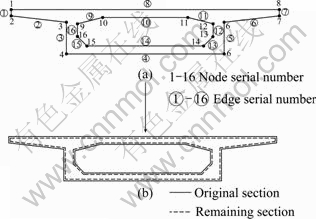
Fig. 1 Reduction of concrete section
Due to the deterioration of materials properties and the reduction of sectional areas, the variation of overall structural performance may be evident over the life-cycle of structure, in which the critical problems are: the loss of concrete dead weight and the internal force redistribution caused by the reduced concrete, reinforcing steel, and prestressing steel sections. The solution of the first problem is: 1) forming the load caused by the reduced concrete section, and 2) acting the load on the deteriorated structure and obtaining the structural response. Note that although the movement of all concrete edges in interior surface and the concrete edge at the top of exterior surface may appear, the dead weight of the reduced areas with respect to these edges is still loaded on the structure. Thus, the loss of dead weight should be merely induced by the movement of all the edges in exterior surface except the top one. In a similar way, the corrosion products of reinforcing and prestressing steels cannot lead to the loss of dead weight, since they are consistently wrapped in the concrete section. The solution of the second problem is: 1) forming the load induced by the internal forces acting on the reduced concrete, reinforcing steel and prestressing steel sections, and 2) applying it on the deteriorated structure and obtaining the structural response. The analysis procedure of the entire degradation process is displayed in Fig. 2.
Based on the abovementioned mechanics analysis, a computer program named CBDAS (i.e. Concrete Bridge Durability Analysis System) is written. Figure 3 shows the flow chart of CBDAS.
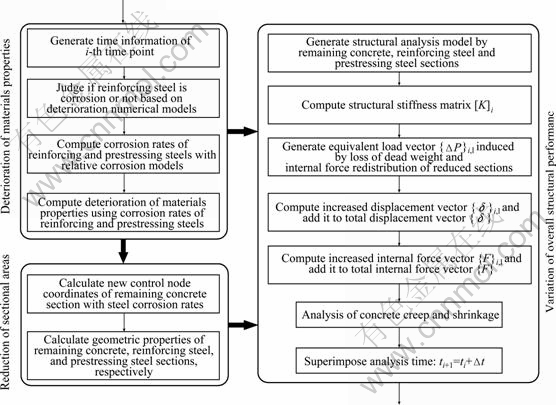
Fig. 2 Assessment of degradation process
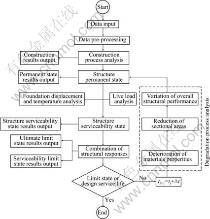
Fig. 3 Flow chart of CBDAS
4 Illustrative example
4.1 Introduction to model bridge
In this work, a 3��25 m three-span prestressed concrete continuous box girder bridge, constructed by using scaffold casting method, is used as illustrative example. The total length of box girder is 75 m and the calculated span is 74 m, as shown in Fig. 4. Grade C50 concretes, 15��S 15.2 and 7��S 15.2, as well as HRB335 are selected for concrete, prestressing steel and reinforcing steel, respectively.
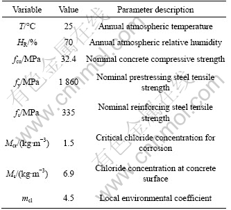
By comparison, the mathematical formulas to evaluate the critical times during degradation process derived from Ref. [17] are utilized here, which are shown in Table 1. The specific meanings of the variables involved in these formulas can be referred to Ref. [17]. Based on the regulations in Refs. [17-18] and structural configuration, values of main design variables involved in assessment are listed in Table 2. The prescribed service life and unit time period are assumed as 100 and 10 a, respectively.
4.2 Simulation results
Figure 5 shows the three critical times with respect to all the concrete edges of the middle span center section. The differences of critical times among the concrete edges are significant, due to the different values of environmental parameters, concrete cover thicknesses and steel bars diameters. Since the environmental condition in interior surface of box section is better than that in exterior surface, the critical time of the interior edges is longer than that of the exterior edges when the other conditions are the same. The earliest corrosion initiation time is 23.5 a and appears in Edge 2, accordingly, the earliest cracking initiation time (i.e. 27.8 a) and concrete cover spalling time (i.e. 29.3 a) likewise appear in this edge. From Fig. 5, it is clear that the time interval from the corrosion initiation time to the concrete cover spalling time is very short. In the case of Edge 2, this time interval is merely 5.8 a. As a result, when the steel bars located in a specific edge of the concrete section initiates to corrode, the concrete cover of this edge may be totally spalled in the following several years.
The results show that the earliest corrosion initiation time of prestressing steel is 560 a, since the concrete cover of prestressing steel is far thicker than that of reinforcing steel. Due to using 100 a as the service life in this work, the corrosion of prestressing steel cannot happen during this period of time. Figure 6 displays the time-increasing area loss rates of reinforcing steel and concrete sections in middle span center. Reinforcing steel initiates to corrode after 23.5 a and its area loss rate is 93.9% at the end of service life. With the development of corrosion, concrete initiates to crack after 27.8 a and its area loss rate is 22.5% at 100 a.
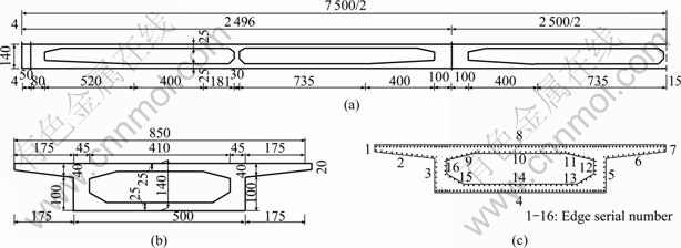
Fig. 4 Profile of PSC box girder bridge: (a) Half elevation of continuous box girder (Unit: cm); (b) Box girder section (Unit: cm); (c) Layout of reinforcing steel
Table 1 Mathematical formulas of critical times
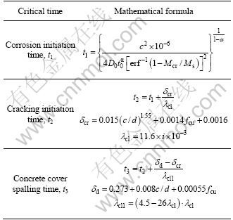
Table 2 Values of main design variables
The variations of concrete normal stresses at two critical locations (i.e. the side-span-center section and the middle-pier-top section) are shown in Fig. 7. It is clear that the structural internal force redistribution is significant during the first 10 a due to the effect of concrete creep and shrinkage. From 10 a to the time point when concrete initiates to crack, the normal stresses are nearly invariant. However, after about 30 a, the significant internal force redistribution appears again. The concrete normal stresses at two locations reach -17.5 MPa and -8.0 MPa (here tensile stress is assumed to be positive) at the end of service life, respectively. Additionally, on one hand, the normal stress at lower edge of side-span-center section reaches -16.2 MPa at 60 a and keeps increasing in the residual service life; on the other hand, the relevant item in the design code [16] prescribes that the minimum concrete compressive stress with respect to the prestressed concrete flexural component at service stage should not be greater than 0.5fcu (i.e. -16.2 MPa in this example). As a result, the performance indicator for the serviceability limit state of the model bridge has exceeded the threshold value after 60 a, mainly due to the reduction of concrete section.
Figure 8 shows the variations of flexural moments and flexural capacities at side-span-center and middle-pier-top sections (here the moment that can induce tensile stress at the lower edge of concrete section is defined as positive). Although the reduction of flexural capacities gets a certain degree, the relative flexural moments are not greater than the flexural capacities throughout the service life. This is because the redundancy of structural flexural capacity is comparatively large at the beginning of service life. Thus, the performance indicators at the ultimate limit state can still satisfy the requirements.
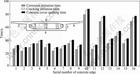
Fig. 5 Critical times in degradation process
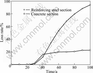
Fig. 6 Time-increasing area loss rates
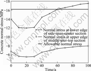
Fig. 7 Variations of concrete normal stresses at critical sections
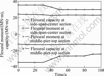
Fig. 8 Variations of flexural moments and capacities at critical sections
5 Conclusions
1) For reinforcing steel, the corrosion initiation time is early and the corrosion rate is fast when the structure is exposed to the environment with chloride penetration. Concrete section initiates to crack soon later and the concrete cover may be totally spelled in a few years.
2) In the case of prestressed concrete bridges, the influence of the reduction of reinforcing steel section on the structural performance related to serviceability limit state is little, and the reduction of concrete section is the essential reason for the variation of structural performance.
3) The prestressing steel is not corroded throughout the service life in the model bridge, since the concrete cover of prestressing steel is far thicker than that of reinforcing steel. For post-tensioned prestressed concrete bridges, the corrosion of prestressing steel is usually not necessary to be considered when the configuration requirements are satisfied.
4) For the prestressed concrete continuous bridges exposed to aggressive environments, performance indicators for the serviceability limit state are likely to exceed the threshold values, but the performance indicators at the ultimate limit state normally can satisfy the requirements throughout the service life.
References
[1] LU Mu. Recent study and research directions of concrete durability [J]. Industrial Construction, 1997, 27(5): 1-6, 27.
[2] CHEN Ai-rong. Design process of bridges based on given structural life [M]. Beijing: China Communications Press, 2009: 1-15.
[3] KUNISHIMA M, OKAMURA H. Durability design for concrete structures [C]// Proceedings of IABSE Symposium. Lisbon, Portugal, 1989: 505-510.
[4] The European Union-Brite Euram III. General guidelines for durability design and redesign [R]. BE95-1347. Bruxelles: Brite-Euram, 2000.
[5] CHEN D, MAHADEVAN S. Chloride-induced reinforcement corrosion and concrete cracking simulation [J]. Cement and Concrete Composites, 2008, 30(3): 227-238.
[6] DARMAWAN M S, STEWART M G. Spatial time dependent reliability analysis of corroding pretensioned prestressed concrete bridge girders [J]. Structural Safety, 2007, 29(1): 16-31.
[7] TIAN Hao. Research on structure performance evolution of concrete bridges in given service life [D]. Shanghai: Tongji University, 2009.
[8] LI Guo-ping. Bridge structure analysis composite system [M]. Shanghai: Tongji University Press, 1998: 6-35.
[9] LI Guo-ping. Prestressed concrete technology and design principle in bridge [M]. Beijing: China Communications Press, 2004: 126-145.
[10] XIAO Ru-cheng. Bridge structure analysis and program system [M]. Beijing: China Communications Press, 2002: 109-117.
[11] LEE H S, NOGUCHI T, TOMOSAWA F. FEM analysis for structural performance of deteriorated RC structures due to rebar corrosion [C]// Proceedings of the second International Conference on Concrete Under Severe Conditions. Tromso, Norway, 1998: 327-336.
[12] JUNG W Y, YOON Y S, SOHN Y M. Predicting the remaining service life of land concrete by steel corrosion [J]. Cement and Concrete Research, 2003, 33(5): 663-677.
[13] AKGUL F, FRANGOPOL D M. Lifetime performance analysis of existing reinforced concrete bridges. ��: Theory [J]. Journal of Infrastructure Systems, 2005, 11(2): 122-128.
[14] AKGUL F, FRANGOPOL D M. Lifetime performance analysis of existing reinforced concrete bridges. ��: Application [J]. Journal of Infrastructure Systems, 2005, 11(2): 129-141.
[15] AKGUL F, FRANGOPOL D M. Lifetime performance analysis of existing prestressed concrete bridge superstructures [J]. Journal of Structural Engineering, 2004, 130(12): 1889-1903.
[16] DARMAWAN M S, STEWART M G. Effect of pitting corrosion on capacity of prestressing wires [J]. Magazine of Concrete Research, 2007, 59(2): 131-139.
[17] CECS 220. Standard for durability assessment of concrete structures [S]. 2007.
[18] JTGD62��2004. Code for design reinforced concrete and prestressed concrete bridges and culverts [S]. 2004.
(Edited by YANG Bing)
Foundation item: Project(2006.318.223.02-01) supported by the Ministry of Transportation and Communications through the Scientific and Technological Funds of China; Project(2007AA11Z104) supported by the High Technology Research and Development of China; Project(20090072110045) supported by the Specialized Research Fund for the Doctoral Program of Higher Education of China
Received date: 2011-03-11; Accepted date: 2011-06-30
Corresponding author: TIAN Hao, PhD; Tel: +86-571-81954829; E-mail: tongjith@gmail.com
Abstract: To accurately evaluate the degradation process of prestressed concrete continuous bridges exposed to aggressive environments in life-cycle, a finite element-based approach with respect to the lifetime performance assessment of concrete bridges was proposed. The existing assessment methods were firstly introduced and compared. Some essential mechanics problems involved in the degradation process, such as the deterioration of materials properties, the reduction of sectional areas and the variation of overall structural performance caused by the first two problems, were investigated and solved. A computer program named CBDAS (Concrete Bridge Durability Analysis System) was written to perform the above-metioned approach. Finally, the degradation process of a prestressed concrete continuous bridge under chloride penetration was discussed. The results show that the concrete normal stress for serviceability limit state exceeds the threshold value after 60 a, but the various performance indicators at ultimate limit state are consistently in the allowable level during service life. Therefore, in the case of prestressed concrete bridges, the serviceability limit state is more possible to have durability problems in life-cycle; however, the performance indicators at ultimate limit state can satisfy the requirements.
