
Trans. Nonferrous Met. Soc. China 29(2019) 322-337
Influence of niobium and molybdenum addition on microstructure and wear behavior of laser-borided layers produced on Nimonic 80A-alloy
N. MAKUCH1, P. DZIARSKI1, M. KULKA1, A. PIASECKI1, M. TULINSKI1, R. MAJCHROWSKI2
1. Institute of Materials Science and Engineering, Poznan University of Technology, Pl. M. Sklodowskiej-Curie 5, 60-965 Poznan, Poland;
2. Institute of Mechanical Technology, Poznan University of Technology, Pl. M. Sklodowskiej-Curie 5, 60-965 Poznan, Poland
Received 29 March 2018; accepted 23 August 2018
Abstract:
Laser alloying was used for production of thick layers on surface of Nimonic 80A-alloy. For laser surface modification, three types of pre-coated pastes were applied: with amorphous boron, with amorphous boron and molybdenum as well as with amorphous boron and niobium. The microstructure, hardness and wear resistance of produced layers were studied in details. The presence of different types of borides in re-melted zone depended on the paste composition and caused an increase in hardness up to about HV 1000. The wear resistance was evaluated by calculation of mass wear intensity factor Imw and relative mass loss of specimen and counter-specimen. The wear behavior of the tested frictional pairs was determined by 3D interference microscopy, scanning electron microscopy equipped with EDS microanalyzer. The significant increase in abrasive wear resistance was observed in comparison to untreated Nimonic 80A-alloy. The lowest mass loss intensity factor was characteristic of laser-alloyed Nimonic 80A-alloy with boron and niobium (Imw=1.234 mg/(cm2��h)). Laser alloyed-layers indicated abrasive wear mechanism with clearly visible grooves. Laser alloying with boron and niobium resulted in the additional oxidative wear mechanism. In this case, EDS patterns revealed presence of oxygen on the worn surface of specimen.
Key words:
laser alloying; surface topography; wear testing; surface analysis; wear mechanism; nickel alloy;
1 Introduction
Nickel alloys are one of the most important classes of engineering materials due to their advantageous properties, e.g. high corrosion resistance and heat resistance. Unfortunately, the main disadvantage of these materials is poor wear resistance that limits their applications. Wear is recognized as the phenomenon of material removal from a surface due to interaction with a mating surface. Almost all the machine components lose their durability and reliability due to the intensive wear. The tribological wear is the process of destruction and removal of material from the surface of solids. This phenomenon is caused by the friction, and manifested by a continuous change of dimensions and shapes of the frictional pair. The causes of wear are in most cases of a mechanical character, less often mechanical, combined with the chemical interaction of the surrounding medium [1]. The possibilities of application of some materials are reduced because of wear problems. Therefore, the protection against wear becomes a primary concern of surface engineering [2]. The formation of hard surface layers can improve the wear resistance of materials. Especially, the surface layers, containing borides, carbides or nitrides, provide the wear protection of substrate material.
Laser surface alloying (LSA) became one of the most developed methods for thermo-chemical treatment of metals and alloys. During LSA, the alloying elements (metallic and non-metallic elements, carbides, oxides, nitrides etc.) are mixed with substrate material. The intensive melting and mixing of the materials take place in a molten pool due to convective, gravitational movement, hydrostatic pressure and vapor pressure generated as a result of the laser beam interaction with treated material [3]. Laser surface alloying involves high heating/cooling rates and gradients which produce metastable phases, leading to the development of a wide variety of microstructures with novel properties that cannot be produced by any conventional processing techniques. By the laser alloying the surface layer of the treated material, it is possible to obtain a fine-grained microstructure. Laser surface alloying (LSA) consists of simultaneous melting and mixing of the alloying elements and the alloyed material (substrate material). The aim of laser alloying is the saturation of treated material with alloying elements. The obtained microstructure, chemical composition, and physical as well as mechanical properties of the laser-alloyed layer are different than those of the substrate material or the alloying material. First of all, the laser-alloyed layer does not exhibit the characteristic layer structure, typical of diffusion processes. The intensive mixing of the alloyed and alloying materials takes place in the molten pool, therefore, there are no transitions from phases with a higher content of the alloying element to phases with lower content. All of phases in the laser-alloyed layer are uniformly distributed along its entire depth. The laser-alloyed layer, rich in alloying components, usually exhibits a higher hardness than the substrate, a higher fatigue strength, better tribological and corrosion properties, but at the same time with poorer smoothness of the surface in comparison with the condition prior to alloying [1]. However, these properties depend to a very high degree on the uniformity of mixing of the alloy in the molten phase, which, in turn, depends on the laser treatment parameters used.
Laser surface alloying was applied in order to improve wear resistance (increase in microhardness, decrease in the coefficient of friction) of different alloys: steels [4-6], titanium alloys [7-11], aluminum alloys [12-14] or copper alloys [15]. In recent years, the laser technology was intensively developed in order to produce thick, hard and wear resistant surface layers on nickel and its alloys [16-25]. In Ref. [16], the hardness and wear resistance of Hastelloy G-alloy were improved by producing of nitride layers. Laser gas-assisted nitriding was carried out using a molecular CO2 laser. This process resulted in the formation of a uniform nitride layer which was characterized by a thickness of 40 ��m and good quality (cracks-free and without porosity). The presence of nitrides (Fe4N and CrN) caused the increase in hardness up to HV 350 in comparison with substrate material (HV 270). Laser alloying of Inconel 600-alloy with boron resulted in the formation of hardened layer [23]. The laser-borided layers were very thick (346-467 ��m depending on the power of the laser beam used) and consisted of nickel, chromium and iron borides and Ni-Cr-Fe matrix (re-melted substrate). The presence of varying types of borides caused an increase in the hardness up to HV 1560. The wear resistance of laser-borided layer was significantly improved in comparison with the untreated Inconel 600-alloy. The laser surface alloying with Si and Al was proposed in order to improve oxidation resistance of Nimonic 80-alloy [19,20]. Laser surface modification of Inconel 625-alloy with TiC and WC particles was also examined [21]. It was found that laser alloying caused a decrease in corrosion resistance, because of the formation of galvanic micro-cells. The laser alloying with boron and niobium was used for the formation of composite boride layer on Nimonic 80A-alloy [24]. The presence of nickel, chromium and niobium borides caused the increase in microhardness up to HV 1000. The produced layers were characterized by ten times higher wear resistance in comparison with untreated Nimonic 80A-alloy.
The aim of this study was to improve the wear resistance of Nimonic 80A-alloy using laser alloying. The surface layer of this alloy was laser-alloyed with boron and niobium or with boron and molybdenum in order to change the wear behavior of the base material. The microstructure, microhardness and wear resistance of laser-alloyed layers were analyzed and discussed.
2 Experimental
2.1 Materials
The base material used for this study was Nimonic 80A-superalloy. This alloy is a wrought, age-hardenable nickel-chromium alloy, strengthened by additions of titanium, aluminum and carbon, developed for service at temperatures up to 815 ��C (1088 K). The alloy��s limiting chemical composition (wt.) was as follows: 0.085% C, 0.09% Si, <0.01% Mn, 0.001% S, 0.01% Cu, 0.25% Fe, 1.44% Al, 2.55% Ti, 19.52% Cr and balance Ni. The specimens in the shape of ring were used for investigation. Their external diameter, internal diameter and height were equal to 20, 12 and 12 mm, respectively.
2.2 Laser surface alloying
Laser surface alloying (LSA) of Nimonic 80A-alloy was realized as a two-stage re-melting process, which consisted of prior deposition of the alloying material on the surface of specimen and subsequent re-melting it with the surface layer of the substrate material. The alloying material was deposited on the external surface of ring-shaped specimen by covering with paste. In this study, three types of pastes were used: based on amorphous boron powder; based on amorphous boron powder and pure niobium powder with the mass ratio of 1:1; based on amorphous boron powder and pure molybdenum powder with the mass ratio of 1.5:1. The alloying powders were diluted in polyvinyl alcohol. The thickness of the deposited paste with alloying elements was (200��5) ��m. Laser alloying was performed using continuous wave CO2 laser (TRUMPF TLF 2600 Turbo). Based on the preliminary investigations, the following laser treatment parameters were applied: laser beam power (P) of 1.56 kW, scanning rate (vl) of 2.88 m/min, laser beam diameter (d) of 2 mm, and average power density of 49.66 kW/cm2. The produced layers were arranged as multiple tracks, with the distance between the axes of the adjacent tracks f=0.28 mm. In order to obtain a uniform layer in respect of its thickness, the high overlapping of adjacent tracks (86%) was used. Laser re-melting is always accompanied by the occurrence of both phenomena plasma and vaporization of material. On the one hand the treated surface is protect by plasma from further laser heating; on the other hand, however, it interacts with the top-surface of the liquid molten pool exerting pressure and causes the displacement of components of the molten materials. In the molten pool, at the site of penetration of the laser beam into the material, a conical pit is formed. The surface of this funnel is acted upon by two types of pressures: the hydrostatic pressure of the liquid material from the below and the vapour pressure from the above. Between actions of these two pressures, an unstable equilibrium is formed, constantly disturbed by relative movement of the laser beam and the treated sample. The conical pit moves towards as yet unmelted material (in a direction opposite to that of the object relative to the beam). Behind the displaced pit, vapour pressure causes a filling in of the discontinuity. For this reason, on the molten surface there appears a characteristic waviness, which is similar to that appearing in a typical weld seam [1].
2.3 Microstructure characterization
The morphology and types of borides, produced on the surface of Nimonic 80A-alloy substrate, were examined using conventional metallographic techniques. Firstly, directly after laser treatment, the phase compositions of laser-alloyed layers were identified using PANalytical EMPYREAN diffractometer with Cu K�� radiation at 45 kV and 40 mA. The scan was taken for 80 min in 2�� range of 20��-100�� with a step of 0.0167��.
For microstructure characterization, the specimens were prepared using the following conventional metallographic procedures: mounting in a conductive resin, grounding using the SiC abrasive paper of varying granularities and polishing with 0.05 ��m Al2O3 paste. In order to reveal the microstructure, all the samples were etched with Marble��s reagent consisting of CuSO4, HCl and water. The cross-section of laser-alloyed Nimonic 80A-alloy was observed with an optical microscope (OM) and a scanning electron microscope (SEM) Tescan Vega 5135. The chemical composition of laser-alloyed Nimonic 80A-alloy with boron and niobium was presented in the previous study [24]. X-ray microanalysis of the specimen, laser-alloyed with boron and molybdenum, was performed using a PGTAvalon X-ray microanalyzer equipped with EDS, using 55�� take-off angle. The contents of boron, molybdenum, chromium and nickel in the surface layer were determined along the line perpendicular to the surface.
2.4 Microhardness profiles
The microhardness vs the distance from the surface was measured using the metallographic specimens which were etched in Marble��s reagent. To determine the microhardness profiles across the laser-alloyed layers, the apparatus ZWICK 3212 B equipped with Vickers diamond indenter was used. The load of 0.981 N and a loading time of 15 s were used during measurements. In order to avoid interaction between the work-hardened regions during measurements, according to norm PN-EN ISO 6507-1, the minimum distance between the centers of adjacent indents was larger than 3d, where d was the average length of diagonals.
2.5 Wear resistance test
The wear resistance tests were performed for the three types of surface layers: laser-alloyed with boron, laser-alloyed with boron and niobium, and laser-alloyed with boron and molybdenum. Nimonic 80A-alloy without laser treatment was also tested for the comparison. Tribological experiments were arranged as a block-on-ring test. In this test, a stationary block was pressed against the outer surface of a rotating ring. The specimen and counter-specimen were in non-conformal contact. The investigated samples were in the shape of ring with the following dimensions: 20 mm of external diameter and 12 mm of internal diameter and height. The counter-specimens were made of sintered carbide S20S in the shape of cuboid with dimensions of 12 mm �� 12 mm �� 5 mm. The materials consisted of carbides (WC, TiC, TaC, NbC) in a Co matrix and are characterized by high hardness (average value of HV 1430). However, their main disadvantage is that they cannot be used at high temperatures because of the tendency to plastic deformation before wear occurs [26]. During the wear resistance test the temperature in the contact area between roller and plate was measured. In all cases the temperature did not exceed 100 ��C (373 K). Therefore, the problem with plastic deformation of counter- specimen did not occur.
The wear resistance tests were performed for 4 h without change in the counter-specimen under dry sliding conditions at ambient temperature in air using a load of 49 N and a sliding speed of 0.26 m/s corresponding to a sliding distance of 3744 m. Before the wear resistance test and after every 0.5 h of test duration, the specimens were weighed on an analytical balance to an accuracy of ��0.05 mg. Their dimensions were measured to an accuracy of ��0.001 mm. The counter- specimens were weighed only before and after 4 h of wear resistance tests. The wear resistance was evaluated by mass wear intensity factor Imw (mg/(cm2��h)). It could be defined as the specimen mass loss per friction surface and unit of time, corresponding to the slope of a straight line in the wear diagram (under conditions of stabilized wear):
 (1)
(1)
where Dm is mass loss (mg), S is friction surface (cm2), and t is friction time (h).
The wear resistance was also evaluated by calculation of relative mass loss. The ��m/mi ratio was determined for the tested specimen and counter-specimen according to the equation:
 (2)
(2)
where mi is initial mass of specimen or counter-specimen (mg), and mf is final mass of specimen or counter-specimen (mg).
In order to characterize the wear mechanisms, the worn surfaces were observed using scanning electron microscope (SEM) equipped with an EDS (energy dispersive spectrometer). The corresponding EDS patterns of some elements from the surface of specimen or a counter-specimen were shown.
The laser alloying process caused the changes in surface roughness of the specimens. However, the surface was not specially prepared before the wear test. Although, the white light 3D interference microscope (WYKO NT-1100) was used to determine the 3D surface profile of untreated and laser-alloyed specimens before and after wear test. During the measurements, the interferometric objective moved vertically to scan the surface at changeable heights. The motion was controlled by translator motor. Due to the short coherence length of white light, interference fringes were visible only for each focus position. Fringe contrast at a single sample point reached a peak if the sample was translated through focus. The system scanned through focus as the camera captured frames of interference data at constant sampling intervals. As the system ended the scans, an interference signal for each point on the surface was recorded. The vertical position equivalent to the peak of the interference signal was released for each point on the surface. In such a measurement, lateral resolution is a function of the magnification objective and the detector array size. Each magnification objective has its own optical resolution based on the magnification and numerical aperture of the objective. The obtained 3D profiles of specimens were analyzed in order to confirm the presence of abrasive wear or adhesive wear after tribological tests. After the wear resistance tests, profiles of the wear tracks generated on the counter-specimens were measured using a Hommel-Etamic T8000 contour measuring system.
In the case of Nimonic 80A-alloy laser alloyed with boron and niobium, after wear resistance test, the phase composition was characterized from surface using a PANalytical EMPYREAN diffractometer with Cu K�� radiation. The aim of this investigation was the confirmation of oxidative mechanism of wear.
3 Results and discussion
3.1 Phase analysis
As a consequence of laser boriding, the presence of chromium borides and nickel borides was expected in the surface layer of nickel-based alloys. Simultaneously, the addition of niobium to the paste coating resulted in the formation of niobium borides. The phase analysis of a surface layer, produced on Nimonic 80A-alloy by laser alloying with boron and niobium, was presented in the previous study [24]. Such a layer contained nickel borides (Ni3B, Ni2B, Ni4B3 and NiB), chromium borides (CrB and Cr2B) as well as niobium borides (NbB2 and NbB). The X-ray diffraction pattern of the top-surface of the laser-alloyed layer with boron and molybdenum was presented in Fig. 1. In this case, the following phases were identified: nickel borides (Ni2B, NiB, Ni3B and Ni4B3), chromium borides (Cr2B), and molybdenum borides (Mo2B, Mo2B5 and MoB). Moreover, a peak of Ni-phase was observed. The intensities of the peaks, corresponding to Ni2B, Ni and Mo2B5, were higher when compared to other phases.

Fig. 1 XRD pattern of Nimonic 80A-alloy laser-alloyed with boron and molybdenum at laser beam power of 1.56 kW
3.2 Linear X-ray microanalysis
Figure 2 showed the results of linear X-ray microanalysis of Nimonic 80A-alloy laser-alloyed with boron and molybdenum. The contents of nickel, chromium, molybdenum and boron were investigated along the axis of laser track. The high intensity of melting and convection during laser alloying caused production of multicomponent layer with strong fluctuations of nickel, chromium, molybdenum and boron contents. The content profiles of these components indicated that all the detected phases occurred alternatively in re-melted zone. As it was observed in the case of laser alloying with boron and niobium, presented in the previous study [24], nickel and chromium contents indicated some segregations. The contents of two main elements of base material (nickel and chromium) in re-melted zone were lower than those of the substrate. This situation was caused by bonding of nickel and chromium atoms with boron atom. This resulted in the formation of nickel borides and chromium borides, respectively. Moreover, the behavior, characteristic of laser-borided layers [23,24], could be observed: a higher nickel content was accompanied by reducing the chromium content. In the areas where the relatively small content of nickel and high content of chromium were measured, the chromium borides occurred in the microstructure. Simultaneously, the relatively small chromium content was observed in areas of high nickel content. Then, the nickel borides predominated in the microstructure.
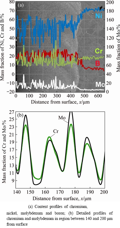
Fig. 2 Results of linear X-ray microanalysis of Nimonic 80A-alloy laser-alloyed with boron and molybdenum at laser beam power of 1.56 kW
The detailed analysis of chromium and molybdenum profiles (Fig. 2(b)) showed that these elements were characterized by a similar distribution across the re-melted zone. The local maxima of chromium content-depth profile were accompanied by the local maxima of molybdenum content-depth profile. For example, according to Fig. 2(b), at the distance from the surface of 147 ��m the content of chromium was equal to 23.48 wt.%, and simultaneously, molybdenum content reached 26.07 wt.%. Similar behavior could be observed at the distance from the surface of 178 ��m: chromium content was equal to 23.68 wt.%, whereas molybdenum content was 27.56 wt.%. This situation was opposite to the distribution of chromium and niobium in laser-alloyed layer with boron and niobium [24]. In that case the niobium profile was quite different from chromium profile. The results of the present study suggested that the chromium and molybdenum borides appeared in the same areas of the re-melted zone.
3.3 Microstructure
Figures 3(a) and (b) showed typical micrographs of laser-borided Nimonic 80A-alloy. High laser beam power of 1.56 kW and the relatively high overlapping of the adjacent laser tracks (86%) caused the formation of thick layer which was uniform in respect of its thickness. The average thickness of about 412 ��m was obtained. The re-melted zone (1) was characterized by dense microstructure consisted of a mixture of different borides (nickel and chromium borides) and the matrix (Fig. 3(b)). The re-melted zone (1) was characterized by compact microstructure without porosity and cracks. Below the laser-alloyed layer, the substrate material (2) was clearly visible. It was characteristic of the laser-alloyed layer, previously produced with boron only [23] that the zone of compact borides without matrix appeared close to the surface. In the present study, such a situation was not observed as a consequence of thinner paste coating with boron (200 ��m).
The modified composition of paste coating (boron and molybdenum) was used in order to produce the surface layer which was visible in Figs. 3(c) and (d). It resulted in diminished thickness of re-melted zone. The addition of molybdenum caused a change in melting condition (heat and mass flow) during laser treatment. Therefore, the average thickness of about 400 ��m was measured for the layer laser-alloyed with boron and molybdenum. The OM observation under higher magnification revealed dendritic microstructure of re-melted zone (1). Beneath re-melted zone (1), the substrate material (2) occurred without visible effects of laser treatment. The microstructure of Nimonic 80A-alloy, laser-alloyed with boron and niobium, was described in the previous study [24]. The thick re-melted zone consisted of mixture of nickel, chromium and niobium borides.
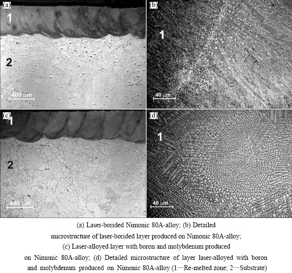
Fig. 3 OM microstructures of produced layers at laser beam power of 1.56 kW
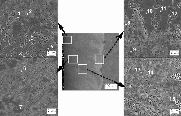
Fig. 4 SEM images of Nimonic 80A-alloy laser-alloyed with boron and molybdenum at laser beam power of 1.56 kW
The SEM images of Nimonic 80A-alloy, laser-alloyed with boron and molybdenum, were shown in Fig. 4. In order to examine the microstructure in details, the SEM images were taken from different areas of the re-melted zone. Simultaneously, the contents of the main elements (nickel, chromium, molybdenum and boron) were measured in 15 different areas of laser-alloyed layer using EDS method. The results of point-wise X-ray microanalysis were specified in Table 1. The four characteristic components of microstructure were clearly visible in the re-melted zone: dark precipitates (marked as 1, 5, 7, 9, 11 and 13 in Fig. 4), large gray precipitates (marked as 3, 4 and 10 in Fig. 4), light dendrites (marked as 2, 6, 8 and 14 in Fig. 4) and matrix (marked as 12 and 15 in Fig. 4). EDS results from the dark precipitates showed the increased chromium and molybdenum contents as well as the relatively low nickel content. This indicated the occurrence of the mixture of chromium borides (Cr2B) and molybdenum borides (Mo2B, Mo2B5 and MoB) in these areas. It should be noticed that chromium and molybdenum borides appeared in the microstructure together. This dependence confirmed the results of detailed X-ray line microanalysis, presented in Fig. 2(b). It also indicated the possibility of formation of complex (Cr,Mo)xBy borides. The light dendrites as well as the large gray precipitates were characterized by high nickel content; whereas the contents of chromium and molybdenum decreased in this area. These dendrites and precipitates occurred across the whole re-melted zone regardless of the distance from the surface. The predominant percentage of a mixture of nickel borides (Ni2B, NiB, Ni3B and Ni4B3) was most probable in these areas. In the matrix area, the contents of nickel and chromium were similar to those of base material. The increased content of boron could result from X-ray emission from the adjacent areas. The EDS detector also measured radiation energy from other phases. The matrix was also alloyed with molybdenum as a consequence of the treatment used.
3.4 Microhardness profiles
The hardness distribution across the produced layers was shown in Fig. 5. The microhardness profiles of laser-alloyed layers with boron, with boron and niobium as well as with boron and molybdenum were compared. Microhardness was measured perpendicular to the laser-alloyed surface along the axis of laser track. As it was expected, laser-alloyed layers were characterized by lower hardness when compared to the layers produced using the diffusion boriding processes. The laser-alloyed layer with boron only was characterized by hardness in the range from HV 520 to HV 950. The presence of nickel borides and chromium borides in the re-melted zone caused an increase in hardness in comparison with the substrate material. At the bottom of laser track, the lower hardness of HV 520-HV 605 was measured. This situation was probably caused by the higher percentage of matrix (substrate material) in re-melted zone.
Table 1 Results of X-ray point-wise microanalysis of Nimonic 80A-alloy after laser alloying with boron and molybdenum
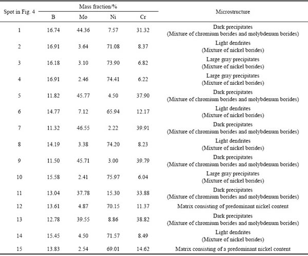
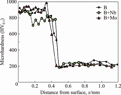
Fig. 5 Microhardness profiles of Nimonic 80A-alloy laser-alloyed with boron, laser-alloyed with boron and molybdenum and laser-alloyed with boron and niobium
In the laser-alloyed layer with boron and molybdenum, the lowest hardness (HV 595) was measured at the end of re-melted zone. The maximal hardness obtained for this layer was equal to HV 990. The laser surface alloying with boron and molybdenum caused the formation of molybdenum borides, nickel borides and chromium borides. It was obvious that measured hardness was significantly lower in this case than that of molybdenum borides [27], chromium borides [28] and nickel borides [29]. Boriding of molybdenum by the spark plasma sintering technology resulted in the hardness of HV 1600-HV 1800. The chromium borides, produced on 99.98 wt.% pure chromium using the pack-boriding method, were characterized by hardness up to HV 1700 [28]; whereas, the hardness of nickel borides, reported in Ref. [29], ranged from HV 1152 to HV 1778. The diminished hardness of laser-alloyed layers resulted from the laser treatment conditions. Laser treatment caused the simultaneous melting of the pre-placed paste coating and substrate material. As a consequence of relatively high laser beam power used (1.56 kW), the high percentage of the substrate was re-melted and mixed with pre-coated paste. Laser alloying with boron and niobium resulted in the formation of a thick layer with a high percentage of substrate material in re-melted zone. Therefore, the hardness ranged from HV 700 to HV 900 in this case. These values were lower than those measured for borides produced using the conventional diffusion processes [27-29].
The characteristic morphology and fine-grained microstructure of borides located in Ni-based matrix in the re-melted zone were the reasons for diminished hardness measured in laser-alloyed layer. The indentation load used for this study was equal to 0.981 N, therefore, the projected area of indents generated in laser-alloyed layer ranged from 100 to 183 ��m2. Such dimensions of projected area caused that the microhardness was measured simultaneously in all types of borides and matrix. Therefore, the obtained values were the average of hardness of borides as well as Ni-Cr matrix.
3.5 Abrasive wear
Abrasive wear resistance test was performed for four types of specimens: non-alloyed (untreated), laser-alloyed with boron only, laser-alloyed with boron and niobium, and laser-alloyed with boron and molybdenum. Firstly, wear resistance was evaluated by calculation of the factor of mass wear intensity Imw. The results obtained for non-alloyed Nimonic 80A-alloy were shown in Fig. 6(a). Figure 6(b) showed the mass loss per unit of friction surface vs friction time for three samples after laser alloying with different types of pre-placed paste.
For untreated Nimonic 80A-alloy, mass wear intensity factor changed during the test. At the beginning, for 2 h, Imw factor was equal to 18.485 mg/(cm2��h). Then, this factor decreased to a value of 10.405 mg/(cm2��h). This situation suggested that after 2 h of wear test, the adhesion between untreated Nimonic 80A-alloy and counter-specimen probably occurred. It was clearly visible that all the graphs, characteristic of laser-alloyed layers, demonstrated linear dependence. The evaluation of Imw indicated the significant increase in wear resistance for all the laser-alloyed layers produced on Nimonic 80A-alloy. The produced laser-alloyed layers were characterized by, approximately, more than nine times lower values of this factor when compared to untreated specimen. However, the calculated mass wear intensity factors differed taking into account the alloying material (pre-placed paste coating).
The highest value of Imw (2.382 mg/(cm2��h)) was obtained in the case of laser-alloyed specimen with boron only. This indicated the lowest wear resistance. The calculated mass wear intensity factor was higher than that reported in Ref. [23], regarding the laser-alloyed Inconel 600 with boron. The thinner paste coating with boron, used in the present study, could result in the formation of a boride layer without the zone of compact borides close to the surface. Such a situation caused the worsened wear behavior of the surface layer. Additionally, the wear test conditions, especially, the use of the same counter-specimen for 4 h, favored the appearance of adhesive wear. This usually diminished the factor of mass wear intensity of laser-borided Inconel 600 alloy [23]. It was probable that the change in wear test conditions, e.g. the use of the counter-specimen for a limited time, could even increase the value of Imw in the case of the base material (Nimonic 80A) used in the present study.
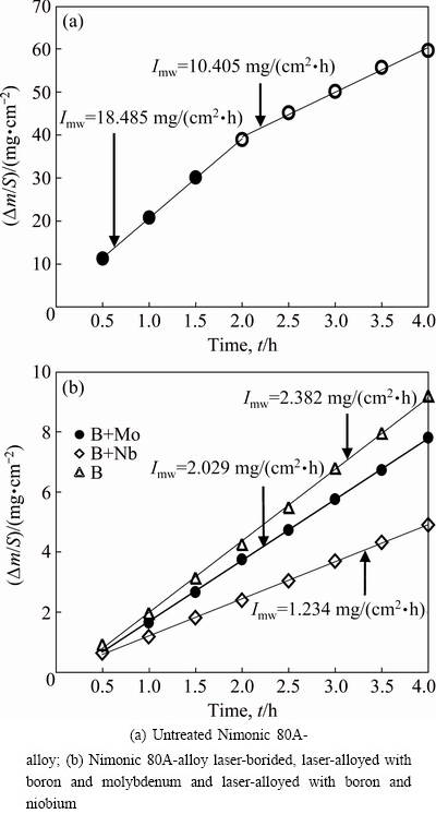
Fig. 6 Results of wear tests showing mass loss per unit of friction surface vs friction time
The laser modification of the surface layer with boron and molybdenum caused a decrease in mass wear intensity factor (Imw=2.029 mg/(cm2��h)). The addition of niobium influenced the value of Imw (1.234 mg/(cm2��h)) even more advantageously. The laser-alloyed specimen with boron and niobium seemed to be 15 times more wear resistant in comparison with untreated specimen. Factor of mass wear intensity was about 35% lower than that reported in the previous study [24]. However, the tests differed in the wear conditions. During the previous investigation, the wear resistance test was carried out for 2 h with the change in the counter-specimen every 0.5 h. In the present study, wear tests were performed for 4 h without change in the counter-specimen. Probably, the conditions of wear tests influenced the wear behavior of laser-alloyed layer with boron and niobium.
The second method of wear resistance evaluation consisted in the calculation of relative mass loss of specimen and counter-specimen. The relative mass loss of each laser-alloyed specimen was only about 1/8 in comparison with that of the untreated specimen (��m/mi= 0.02326). However, the lowest value of relative mass loss characterized Nimonic 80A-alloy after laser-alloying with boron and niobium (��m/mi=0.001896). The use of a mixture of boron and molybdenum as an alloying material resulted in the higher value of ��m/mi (0.00303). The slightly higher relative mass loss (��m/mi=0.0036) was characteristic of laser-alloyed layer with boron only.
Simultaneously, the relatively small wear of the counter-specimen was calculated for all the laser-alloyed layers as well as untreated Nimonic 80A-alloy. The highest relative mass loss of counter-specimen (��m/mi= 0.00103), mating with the untreated Nimonic 80A-alloy, was only seemingly unexpected. The relatively high percentage of adhesive wear could be the reason for such a situation. The lowest mass loss of counter-specimen (��m/mi=0.000088) was obtained in the case, when the laser-alloyed specimen with boron and molybdenum was used as a mating material. Probably, such results indicated differences in the wear mechanism of the investigated specimens.
The surface profiles of the wear tracks generated on the counter-specimen surface after wear resistance tests were presented in Fig. 7. The results confirmed that the highest volume loss of counter-specimen was characteristic of untreated Nimonic 80A-alloy. In this specimen, the depth of the wear track was equal to approximately 15 ��m. Laser-alloyed layers were characterized by the lower depth of wear tracks in counter-specimen: 9, 6 and 11 ��m for laser-alloyed specimens with boron, boron and molybdenum, boron and niobium, respectively. A significant difference was clearly visible between the obtained profiles for untreated Nimonic 80A-alloy and laser-alloyed specimens. In the case of untreated specimen, the surface profile of the wear tracks generated on the counter- specimens had a very irregular shape when compared to other samples. Probably, in the areas with a low depth of wear track, the adhesion craters could appear on the surface.
The differences in the results of wear tests induced the need of detailed analysis of worn surfaces. The 3D surface profiles of untreated Nimonic 80A-alloy as well as laser-alloyed with boron and niobium and with boron and molybdenum were investigated before and after wear tests. The 2D and 3D surface profiles of untreated Nimonic 80A-alloy before the wear test were presented in Fig. 8.
In Fig. 8, the surface was uniform, without craters or cracks. Only the effects of mechanical machining were visible. No significant differences in surface topography were observed. The wear test caused changes in surface topography of untreated Nimonic 80A-alloy (Fig. 9). The worn surface was characterized by obvious signs of severe plastic deformation (in the middle of worn surface) as well as abrasive wear, evidenced by shallow grooves. The presence of some adhesion craters was also probable.
As it was expected, laser alloying caused changes in surface topography (Figs. 10-13) when compared to the untreated specimen (Fig. 8). In the case of laser-alloyed Nimonic 80A with boron and molybdenum before wear test, some elevations appeared on the surface (Fig. 10). It was evidenced by red points in the surface topography profile. Comparing the detailed microstructure analysis (Fig. 4) with the surface profile, it could be assumed that these elevations, obtained on the 3D surface topography, corresponded to the mixture of chromium and molybdenum borides identified in SEM images. After the wear resistance test, the signs of intensive abrasive wear were observed on the worn surface (Fig. 11). The shallow grooves appeared predominantly on the specimen surface. However, in some areas deeper grooves occurred. No signs of plastic deformation were visible; whereas the presence of an amount of adhesion craters was probable.

Fig. 7 Surface profiles of wear tracks generated on counter-specimen surfaces after wear resistance tests
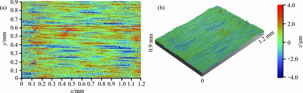
Fig. 8 2D (a) and 3D (b) images of surface topography of untreated Nimonic 80A-alloy before wear test
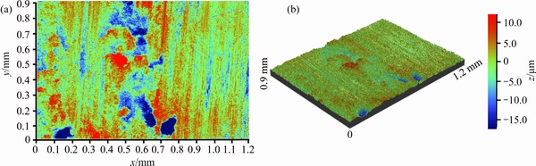
Fig. 9 2D (a) and 3D (b) images of surface topography of untreated Nimonic 80A-alloy after wear test
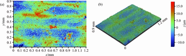
Fig. 10 2D (a) and 3D (b) images of surface topography of Nimonic 80A-alloy laser-alloyed with boron and molybdenum before wear test
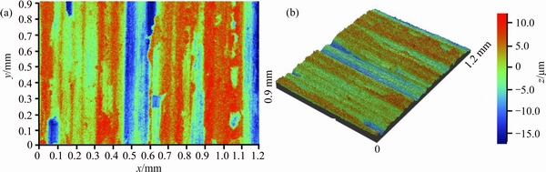
Fig. 11 2D (a) and 3D (b) images of surface topography of Nimonic 80A-alloy laser-alloyed with boron and molybdenum after wear test
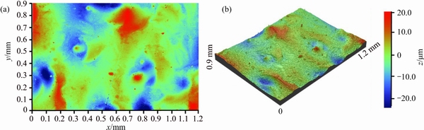
Fig. 12 2D (a) and 3D (b) images of surface topography of Nimonic 80A-alloy laser-alloyed with boron and niobium before wear test
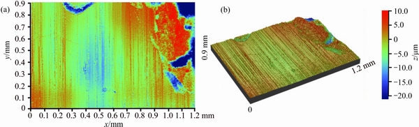
Fig. 13 2D (a) and 3D (b) images of surface topography of Nimonic 80A-alloy laser-alloyed with boron and niobium after wear test
Laser alloying with boron and niobium resulted in the modified surface (Fig. 12), which was characterized by the greatest difference in height. It could be caused by the intensive melting and mixing in the liquid molten pool. The obvious signs of abrasive wear, evidenced by many shallow grooves, could be observed on the worn surface of laser-alloyed specimen with boron and niobium (Fig. 13). In the upper-right corner of worn surface, some signs of plastic deformation appeared. The 3D surface profiles of the laser-alloyed samples before wear tests indicated that the convection and vortex motions during laser melting were primarily responsible for mixing. Therefore, they influenced the surface topography. After the wear tests, the surface topography changed depending on the type of specimen. In the case of untreated Nimonic 80A-alloy, strong plastic deformation was observed; whereas the surfaces of laser-alloyed Nimonic 80A-alloy indicated the abrasion as a predominant wear mechanism.
In order to get detailed description of wear behavior of the tested samples, the worn surfaces were observed using scanning electron microscopy (SEM) equipped with EDS. The SEM images of the surface and EDS patterns of some elements were analyzed for specimens and counter-specimens. The worn surfaces of frictional pair, consisting of untreated Nimonic 80A-alloy and counter-specimen (sintered carbides S20S), were presented in Fig. 14. The corresponding EDS patterns of main elements of specimen (Ni, Cr) and counter- specimen (Co and W) were also shown. Additionally, the eventual presence of oxygen was analyzed. The smooth grooves and some adhesion craters appeared in Area 1 of Nimonic 80A-alloy. This suggested the abrasive and adhesive wear mechanism. The grooves were formed as a consequence of a wear particle generation and plastic flow of material to form ridges on both sides of a groove. In Area 2 of Fig. 14, the strong plastic deformation was clearly visible. The analysis of EDS patterns indicated that the worn surface of Nimonic 80A-alloy mainly contained elements derived from specimen. However, an amount of oxygen and the elements characteristic of counter-specimen (Co and W) were also detected. Worn surface of the counter-specimen was characterized by the areas which differed in chemical composition. In the central area of SEM image, only characteristic elements of sintered carbide S20S (Co and W) occurred. Additionally, an amount of oxygen was observed in this region. However, there were also the areas of increased contents of nickel and chromium. Probably, some very fine particles became detached from the specimen and agglomerated in some areas of the counter-specimen surface. Summarizing, the wear mechanism of untreated Nimonic 80A could be characterized as abrasive, adhesive and oxidative mechanism.
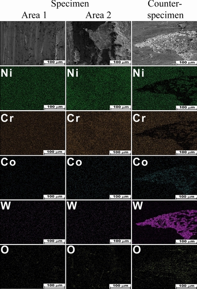
Fig. 14 SEM images and EDS patterns of worn surface of frictional pair consisting of untreated Nimonic 80A-alloy and counter-specimen (sintered carbide S20S)
The SEM images and EDS patterns, obtained from the worn surfaces of laser-alloyed Nimonic 80A with boron and molybdenum and counter-specimen (sintered carbide S20S), were presented in Fig. 15. The smooth grooves were clearly visible in SEM images of worn laser-alloyed sample. It confirmed the abrasion as the predominant wear mechanism. EDS patterns indicated that the specimen surface has been usually free from large signs of adhesion. The worn surface of laser- alloyed Nimonic 80A with boron and molybdenum was mainly characterized by the presence of elements of specimen (nickel, chromium, molybdenum). The observation of Area 2 was carried out using higher magnification. Hence, the details of microstructure were more visible. EDS patterns of chromium, molybdenum and nickel confirmed that the chromium borides and molybdenum borides occurred together in microstructure as dark precipitates, similarly like those observed in Fig. 4. The worn surface of the counter-specimen also revealed the adhesive mechanism of wear. The EDS patterns showed the presence of elements characteristic of a specimen (nickel, chromium, molybdenum). The specimen particles, especially from the areas with more percentage of base material, were displaced by hard particles of sintered carbide (e.g. tungsten carbides) from the sample surface to the surface of a counter-sample. Simultaneously, there were no clear signs of oxidation on the surface of specimen or counter-specimen.
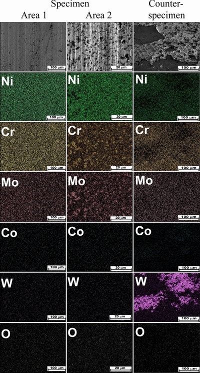
Fig. 15 SEM images and EDS patterns of worn surface of frictional pair consisting of Nimonic 80A-alloy laser-alloyed with boron and molybdenum and counter-specimen (sintered carbide S20S)
Laser surface alloying with boron and niobium caused almost two times increase in wear resistance when compared to laser alloying with boron and molybdenum. The significantly lower mass loss during wear test suggested the occurrence of more complex wear mechanism. Therefore, the detailed analysis of worn surfaces was very important. It was shown in Fig. 16. Three different areas of the specimen were analyzed. Area 1 demonstrated shallow grooves, characteristic of the abrasive wear mechanism. Worn surface of specimen mainly included the elements of specimen (nickel, chromium, niobium). The adhesion craters were invisible. However, the slightly increased content of oxygen could be observed on the whole surface of the specimen. Areas 2 and 3 in Fig. 16 were observed at higher magnification. They differed considerably in comparison with Area 1. Strong pill-up of material (light areas) was visible in the SEM images. The decreased contents of nickel, chromium and niobium were observed in these regions. It was accompanied by the relatively high content of oxygen. Such an effect was a novelty in comparison with the laser-alloyed Nimonic 80A-alloy with boron and molybdenum. The addition of niobium to alloying material essentially changed wear behavior of the laser-alloyed layer. The presence of oxygen on the worn surface of specimen indicated the oxidative wear mechanism. To confirm such a wear behavior, X-ray diffraction analysis was carried out on the specimen surface after the wear test.
Figure 17 showed XRD pattern of laser-alloyed Nimonic 80A with boron and niobium, subjected to wear test for 4 h. The results confirmed the presence of chromium, nickel and niobium borides as well as niobium oxides NbO and NbO2. The appearance of niobium oxides on the worn surface of specimen resulted from the reactions at a contact of frictional pair. During wear testing of metallic materials, the frictional heat usually generated such processes as oxidation, soft skin of steel or hydrogen embrittlement close to the surface. For the contact of metallic materials with air, oxidation was the most significant reaction. The presence of niobium oxides after wear test of boronized niobium was previously reported in Ref. [30]. Borided layer consisted of niobium borides NbB and NbB2. Wear behavior was examined in dry and wet conditions. X-ray diffraction was used in order to identify the presence of oxides. After test in dry condition, the peaks characteristic of niobium oxide NbO were identified; whereas the addition of lubricant caused the formation of Nb2O5 phase. These results confirmed the possibility of oxidation of the surface layers with niobium borides subjected to the wear test. In the present study, the worn surface of the counter-specimen was also analyzed. In this case, the signs of adhesion and oxidation were less visible.
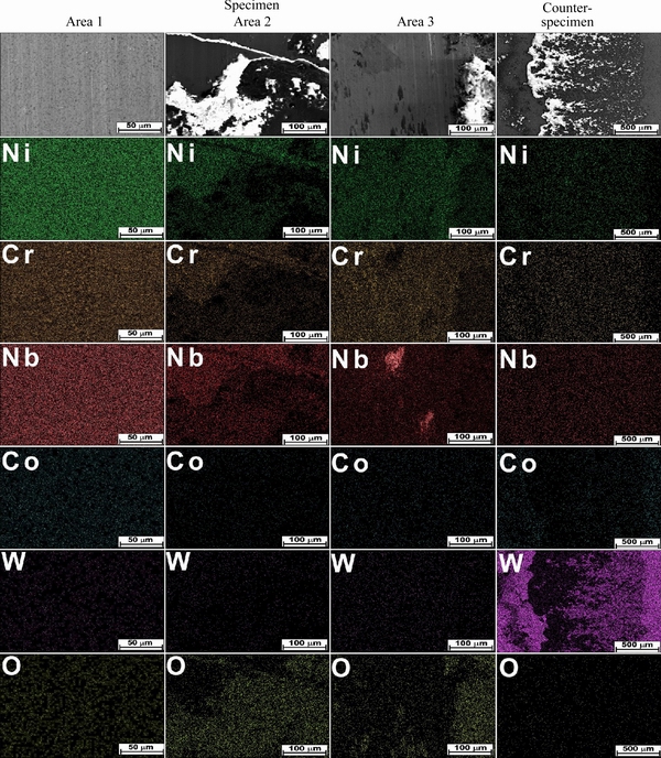
Fig. 16 SEM images and EDS patterns of worn surface of frictional pair consisting of Nimonic 80A-alloy laser-alloyed with boron and niobium and counter-specimen (sintered carbide S20S)
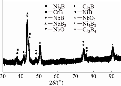
Fig. 17 XRD patterns of Nimonic 80A-alloy laser-alloyed with boron and niobium after wear test for 4 h
4 Conclusions
(1) The laser modification of Nimonic 80A-alloy with boron and molybdenum or with boron and niobium resulted in the changes in the microstructure compared to the only laser-borided layer. For each specimen, nickel borides and chromium borides appeared as a result of presence of boron in pre-coated paste and nickel and chromium in the treated material. However, the addition of molybdenum also caused formation of Mo2B, Mo2B5 and MoB borides; whereas in the case of laser alloying with boron and niobium, the borides (NbB2 and NbB) were additionally identified.
(2) The presence of hard borides in the re-melted zone caused the increase in microhardness up to about 1000 HV for each sample.
(3) The produced laser-alloyed layers were characterized by increased wear resistance in comparison with untreated Nimonic 80A-alloy. The layers, laser- alloyed with boron and with boron and molybdenum demonstrated similar mass wear intensity factors: 2.382 and 2.029 mg/(cm2��h), respectively. Laser-alloyed Nimonic 80A-alloy with boron and niobium was characterized by the higher wear resistance, obtaining the relatively low value of Imw (1.234 mg/(cm2��h)).
(4) Detailed analysis of the topography of worn surfaces as well as EDS microanalysis revealed considerable differences in wear behavior of investigated frictional pairs. The untreated specimen was characterized by strong plastic deformation; whereas for laser-alloyed layers, the abrasive wear mechanism predominated. In the case of laser-alloyed specimen with boron and niobium, the signs of oxidation also occurred. The XRD phase analysis of this specimen after wear test indicated the presence of oxidative wear mechanism. As a result, the lowest mass loss was measured.
Acknowledgments
This article was partially financially supported within the project "Engineer of the Future. Improving the didactic potential of the Poznan University of Technology" - POKL.04.03.00-00-259/12, implemented within the Human Capital Operational Programme, co-financed by the European Union within the European Social Fund and partially by Ministry of Science and Higher Education in Poland as a part of the 02/24/DSPB project.
References
[1] BURAKOWSKI T, WIERZCHON T. Surface engineering of metals: Principles, equipment, technologies [M]. Washington: CRC Press, 1999.
[2] BHUSHAN B. Modern tribology handbook [M]. London: CRC Press, 2001.
[3] NEE A Y C. Handbook of manufacturing engineering and technology [M]. London: Springer-Verlag, 2015.
[4] BONEK M. Formation of hard composite layer on tool steel by laser alloying [J]. Archives of Metallurgy of Materials, 2016, 61(2): 719-724.
[5] PIASECKI A, KOTKOWIAK M, KULKA M. Self-lubricating surface layers produced using laser alloying of bearing steel [J]. Wear, 2017, 376-377: 993-1008.
[6] KULKA M, MIKOLAJCZAK D, MAKUCH N, DZIARSKI P, MIKLASZEWSKI A. Wear resistance improvement of austenitic 316L steel by laser alloying with boron [J]. Surface & Coatings Technology, 2016, 291: 292-313.
[7] ADEBIYI D I, POPOOLA A P I. Mitigation of abrasive wear damage of Ti-6Al-4V by laser surface alloying [J]. Materials and Design, 2015, 74: 67-75.
[8] TIAN Y S, CHEN C Z, CHEN L X, HUO Q H. Microstructures and wear properties of composite coatings produced by laser alloying of Ti-6Al-4V with graphite and silicon mixed powders [J]. Materials Letters, 2006, 60: 109-113.
[9] MAKUCH N, KULKA M, DZIARSKI P, PRZESTACKI D. Laser surface alloying of commercially pure titanium with boron and carbon [J]. Optics and Lasers in Engineering, 2014, 57: 64-81.
[10] TIAN Y S, CHEN C Z, WANG D Y, HUO Q H, LEI T Q. Laser surface alloying of pure titanium with TiN-B-Si-Ni mixed powders [J]. Applied Surface Science, 2005, 250: 223-227.
[11] OCELIK V, MATTHEWS D, de HOSSON J T H M. Sliding wear resistance of metal matrix composite layers prepared by high power laser [J]. Surface & Coatings Technology, 2005, 197: 303-315.
[12] MABHALI L A B, SACKS N, PITYANA S. Three body abrasion of laser surface alloyed aluminium AA1200 [J]. Wear, 2012, 290-291: 1-9.
[13] RAJAMURE R S, VORA H D, GUPTA N, KAREWAR S, SRINIVASAN S G, DAHOTRE N B. Laser surface alloying of molybdenum on aluminum for enhanced wear resistance [J]. Surface & Coatings Technology, 2014, 258: 337-342.
[14] TIAN Y S, GE R. Laser fabrication of nickel aluminide coatings on Al2024 alloy [J]. Materials Science and Technology, 2013, 29(3): 314-318.
[15] KAC S, RADZISZEWSKA A, KUSINSKI J. Structure and properties of the bronze laser alloyed with titanium [J]. Applied Surface Science, 2007, 253: 7895-7898.
[16] YILBAS B S, AKHTAR S S, KARATAS C. Laser gas assisted nitriding of Hastelloy G alloy: Thermal stress analysis and characterization [J]. Surface and Interface Analysis, 2012, 44: 352-364.
[17] YILBAS B S, KHALED M, GONDAL M A. Electrochemical response of laser surface melted Inconel 617 alloy [J]. Optics and Lasers in Engineering, 2001, 36: 269-276.
[18] PETRONIC S, KOVACEVIC A G, MILOSAVLJEVIC A, SEDMAK A. Microsructural changes of Nimonic-263 superalloy caused by laser beam action [J]. Physica Scripta, 2012, 149: 1-4.
[19] MAJUMDAR J D, MANNA I. Laser-surface alloying of nimonic 80 with silicon and aluminum and its oxidation behavior [J]. Metallurgical and Materials Transactions A, 2012, 43: 3786-3796.
[20] RODRIGUEZ G P, GARCIA I, DAMBORENEA J. Effects of laser surface modification of nimonic with aluminum on oxidation behavior [J]. Oxidation of Metals, 2002, 58: 235-248.
[21] COOPER K P, SLEBODNICK P, THOMAS E D. Seawater corrosion behavior of laser surface modified Inconel 625 alloy [J]. Materials Science and Engineering A, 1996, 206: 138-149.
[22] DEY G K, KULKARNI U D, BATRA I S, BANERJEE S. Laser surface alloying of nickel by molybdenum and aluminium�C Microstructural studies [J]. Acta Metallurgica et Materialia, 1994, 42: 2973-2981.
[23] KULKA M, DZIARSKI P, MAKUCH N, PIASECKI A, MIKLASZEWSKI A. Microstructure and properties of laser-borided Inconel 600-alloy [J]. Applied Surface Science, 2013, 284: 757-771.
[24] MAKUCH N, PIASECKI A, DZIARSKI P, KULKA M. Influence of laser alloying with boron and niobium on microstructure and properties of Nimonic 80A-alloy [J]. Optics and Laser Technology, 2015, 75: 229-239.
[25] ZHANG B, BI G, NAI S, SUN C H, WEI J. Microhardness and microstructure evolution of TiB2 reinforced Inconel 625/TiB2 composite produced by selective laser melting [J]. Optics & Laser Technology, 2016, 80: 186-195.
[26] OSTBERG G, BUSS K, CHISTENSEN M, NORGREN S, ANDREN H O, MARI D, WAHNSTROM G, REINECK I. Effect of TaC on plastic deformation of WC-Co and Ti(C,N)-WC-Co [J]. International Journal of Reflactory Metals, 2006, 24: 145-154.
[27] YU L G, KHOR K A, SUNDARARAJAN G. Boride layer growth kinetics during boriding of molybdenum by the spark plasma sintering (SPS) technology [J]. Surface & Coatings Technology, 2006, 201: 2849-2853.
[28] USTA M, OZBEK I, BINDAL C, UCISIK A H, INGOLE S, LIANG H. A comparative study of borided pure niobium, tungsten and chromium [J]. Vacuum, 2006, 80: 1321-1325.
[29] GUNES I, KAYALI Y. Investigation of mechanical properties of borided nickel 201 alloy [J]. Materials and Design, 2014, 53: 577-580.
[30] RIBEIRO R, INGOLE S, USTA M, BINDAL C, UCISIK A H, LIANG H. Tribological characteristics of boronized niobium for biojoint applications [J]. Vacuum, 2006, 80: 1341-1345.
����������Nimonic 80A�Ͻ���������֯��ĥ����Ϊ��Ӱ��
N. MAKUCH1, P. DZIARSKI1, M. KULKA1, A. PIASECKI1, M. TULINSKI1, R. MAJCHROWSKI2
1. Institute of Materials Science and Engineering, Poznan University of Technology, Pl. M. Sklodowskiej-Curie 5, 60-965 Poznan, Poland;
2. Institute of Mechanical Technology, Poznan University of Technology, Pl. M. Sklodowskiej-Curie 5, 60-965 Poznan, Poland
ժ Ҫ����Nimonic 80A�Ͻ�����ü���Ͻ����Ʊ��Ϻ�ı��㡣 ����������ǰ�ڲ��ϱ���ԤͿ��3�ֽ��ϣ��Ǿ��𡢷Ǿ�������ͷǾ������ꡣ��ϸ�о����������������֯��Ӳ�Ⱥ���ĥ���ܡ���������ͬ����������γ��뽬�ϳɷ��йأ���Ӳ�����ӣ��ɴ�HV 1000���ҡ�ͨ��������Ʒ�Ͷ�ĥ��������ĥ��ǿ������Imw�����������ʧ��������Ʒ����ĥ�ԡ�������ά����������ɨ��羵�͵��������DZ���Ħ������ĥ����Ϊ����δ������Nimonic 80A�Ͻ���ȣ��������ĺϽ�����ĥ��������ߡ���������Nimonic 80A �Ͻ�Ͻ�ı��������͵�������ʧǿ������(Imw=1.234 mg/(cm2��h))������Ͻ���Ĺ��������ɼ�����ĥ�����Ϊĥ��ĥ�𡣾�������������Ͻ�����������ͼ�����������ڣ����ֳ����������ĥ����ơ�
�ؼ��ʣ�����Ͻ�������ò��ĥ����ԣ����������ĥ����ƣ������Ͻ�
(Edited by Wei-ping CHEN)
Corresponding author: N. MAKUCH; E-mail: makuch@put.poznan.pl
DOI: 10.1016/S1003-6326(19)64942-3
Abstract: Laser alloying was used for production of thick layers on surface of Nimonic 80A-alloy. For laser surface modification, three types of pre-coated pastes were applied: with amorphous boron, with amorphous boron and molybdenum as well as with amorphous boron and niobium. The microstructure, hardness and wear resistance of produced layers were studied in details. The presence of different types of borides in re-melted zone depended on the paste composition and caused an increase in hardness up to about HV 1000. The wear resistance was evaluated by calculation of mass wear intensity factor Imw and relative mass loss of specimen and counter-specimen. The wear behavior of the tested frictional pairs was determined by 3D interference microscopy, scanning electron microscopy equipped with EDS microanalyzer. The significant increase in abrasive wear resistance was observed in comparison to untreated Nimonic 80A-alloy. The lowest mass loss intensity factor was characteristic of laser-alloyed Nimonic 80A-alloy with boron and niobium (Imw=1.234 mg/(cm2��h)). Laser alloyed-layers indicated abrasive wear mechanism with clearly visible grooves. Laser alloying with boron and niobium resulted in the additional oxidative wear mechanism. In this case, EDS patterns revealed presence of oxygen on the worn surface of specimen.
