
Trans. Nonferrous Met. Soc. China 22(2012) s528-s533
3D numerical analysis of material flow behavior and flash formation of 45# steel in continuous drive friction welding
JI Shu-de1, LIU Jian-guang2, YUE Yu-mei1,  Zan1, FU Li1
1. Faculty of Aerospace Engineering, Shenyang Aerospace University, Shenyang 110136, China;
2. School of Materials Science and Engineering, Harbin Institute of Technology, Harbin 150001, China
Received 28 August 2012; accepted 25 October 2012
Abstract:
The flow behaviour and flash formation of ring component for 45# steel in continuous drive friction welding (CDFW) process were investigated. A 3D thermo-mechanical coupled finite element method was used to conduct this research. Seven welding schemes with different friction pressures, friction times and rotational velocities were carried out. The influences of friction pressure, friction time and rotational velocity on the material flow behaviour at the friction surface and flash formation were analyzed. Research results show that higher peak temperature, larger region with high temperature and larger axial pressure are all good for the increase of material flow velocity. During the CDFW process, the material near the edge of friction surface flows towards the outside of joint, which makes the appearance of flashes. With the increase of rotational velocity, friction time and friction pressure, the dimensions and the bending degree of flashes increase. The reasonable welding parameters of ring structure for 45# steel, whose inner diameter and outer diameter are 50 mm and 80 mm, respectively, are the friction pressure of 100 MPa, the friction time of 4 s and the rotational velocity of 1600 r/min.
Key words:
continuous drive friction welding (CDFW); 45# steel; temperature field; material flow; flash; finite element simulation; welding parameters;
1 Introduction
Continuous drive friction welding (CDFW) is a kind of solid state technology, and is an early developed friction welding method. In the process of CDFW, one of the two components to be welded is held stationary while the other is rotated, which results in the friction heat generated in the friction surface. And the weld joint is formed under the axial pressure with which the two components are pushed against each other. Therefore, the material with high temperature may undergo the violent plastic deformation, large strain and large strain rate under the condition of high axial pressure [1]. Moreover, the size of grains in the region with high temperature is greatly finer than that of parent metal, which results in good mechanical properties of CDFW joints [2-4]. So far, CDFW can be widely used in the manufacture of valve, drill pipe, bearing, bimetal valve, etc [5,6].
Similar to other friction welding methods [7-10], the material undergoes the forging process and is squeezed out of the friction surface, so the flow behavior of material happens and the flashes appear [11,12]. In fact, the flow behavior of material during the CDFW process is related to the temperature, the microstructure, the flashes and then the mechanical properties of joints. However, the CDFW process is a very complicated thermal-mechanical coupled process while the temperature evolution must be involved in the research of material flow behavior resulting from the plastic deformation, which makes the research process difficult solely by experiment [13]. With the advancement of computer technology, the finite element analysis is used to analyze the CDFW process [13-15]. LI and WANG [13] established a detailed 2D finite element model of CDFW to evaluate the interface temperature and axial shortening during the welding process by using the software ABAQUS. ZHANG et al [15] showed that the 3D model is better than the 2D model from the viewpoint of describing the welding process of CDFW. However, no researcher has studied the material flow in the process of CDFW in detail.
In this work, a detailed 3D thermo-mechanical coupled finite element analysis model is established by using the software DEFORM, on basis of which the material flow behavior and the flashes formation are studied.
2 Coupled thermo-mechanical model
2.1 Mesh generation
In this work, a CDFW process of ring structure of 45# steel was analyzed. The dimensions of rotational component are the same as those of the stationary component. The inner diameter of ring structure is 50 mm while the outer diameter is 80 mm. In order to simplify the computation process, the rotational component is replaced by the rigid body which can conduct heat. The discrete mesh of ring used in the numerical simulation is shown in Fig. 1.

Fig. 1 Mesh generation of ring
The tetrahedron element with four nodes is used to describe the component. In the CDFW process, the temperature of material in and near the friction surface is very high [7], so the fine elements are used to describe this region. In order to save the computation time, the region with relatively low temperature is made up of the coarse elements. Moreover, the automatic remeshing technology adopted by the DEFORM software was used to deal with the distortion problem of elements.
2.2 Welding parameters and boundary condition
Figure 2 shows the rotational velocity changes with welding time. Generally, the CDFW process can be divided into four stages: initial friction stage, friction stage, stopping stage and forging stage. In the initial friction stage (0-0.1 s), the rotational velocity of component and the axial friction pressure both rapidly increase to the maximum. In the stable friction stage (0.1-4 s), the rotational velocity of component and the axial friction pressure keep constant. In the stopping stage (4-4.5 s), the rotational velocity linearly decreases to 0 while the axial forging pressure linearly increases from the axial friction pressure to 200 MPa. In the forging stage (4.5-7 s), the value of forging pressure keeps at 200 MPa.

Fig. 2 Rotational velocity of component during CDFW process
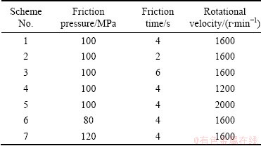
In order to analyze the effect of the welding parameters on material flow and the flashes shape, seven schemes were designed, as shown in Table 1. For any scheme, the axial forging pressure is 200 MPa and the forging time is 2.5 s.
Table 1 Welding procedure schemes of CDFW of 45# steel
In the simulation process, the nodes on the surface of the stationary component which is parallel to the friction surface are completely constraint. The axial friction pressure in the friction stage and the axial forging pressure in the forging stage are both applied to the surface of the rotational component which is parallel to the friction surface, while the direction of pressure is perpendicular to the friction surface.
2.3 Friction coefficient
The Coulomb friction model was used to describe the friction behaviour of CDFW process. Figure 3 shows the relationship between the friction coefficient and the temperature. The friction coefficient is influenced by many factors, such as material properties, contacting force, and temperature. In the present work, the friction coefficient used refers to the data in Ref. [16].
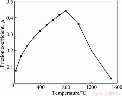
Fig. 3 Relationship between friction coefficient and temperature
3 Results and discussion
3.1 Material flow behavior in CDFW process
For any schemes in Table 1, the temperature and the flow behaviour of materials are both similar. So, scheme 1 is mainly discussed in the following part. Figure 4 shows the relationship between the peak value of material temperature in friction surface and the welding time. Figure 5 shows the flow velocity of material in the friction surface at the different welding time. It is known from Fig. 4 and Fig. 5 that the material in the middle region of friction surface flows along the rotational direction of component. The material near the edges of friction surface flows not only along the rotational direction of component but also towards the outside of friction surface. In the initial friction stage, the material flows slowly (Fig. 5 (a)), which results from the low temperature and the high flow stress of material. With the proceeding of welding process, the welding temperature of material in friction surface increases and then reaches a constant value, which results in the increase of the material flow velocity (Fig. 5(b)). In the final friction stage, the temperature doesn��t increase while the high temperature region near the friction surface increases because of heat conductivity, which results in the decrease of constraint of material on the material in friction surface and then makes the material flow velocity go on increasing (Fig. 5(c)). In the stopping stage, with the increase of the axial pressure, the material flow velocity rapidly increases (Figs. 5(d) and (e)). In the forging stage, the rotational velocity is zero and the temperature in friction surface gradually decreases, which causes that the material flow velocity becomes to zero (Fig. 5(f)).
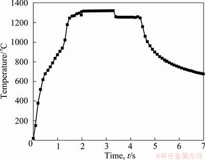
Fig. 4 Variation of peak temperature with welding time
Figure 6 shows the flow velocity vector of material in different sections parallel to the friction surface at 4 s. 1 mm and 2 mm in Fig. 6 represent respectively the distances from one section to friction surface. From Fig. 5(c) and Fig. 6, it is known that the material flow velocity in the edge of any section is larger than that in the middle of surface, which can be explained by the law of minimum resistance in plastic forming theory. Moreover, the material flow velocity decreases with the increase of distance away from the friction surface.
3.2 Flash formation in welding process
Figure 7 shows the process of flashes formation in the CDFW process. From Fig. 5, Fig. 6 and Fig. 7, it can be known that the material in and near the friction surface flows towards the edge of friction surface and then the flashes appear. In the friction stage, the flow velocity of material towards the edge of friction surface is very low and then the dimensions of flashes are very small (as shown in Fig. 7(a)). In the stopping stage, the flow velocity of material rapidly increases, which results in the increase of the dimensions of flashes (Figs. 7(b)-(d)).
Figure 8 shows the flash shapes under different welding schemes. It can be seen that the dimensions and the bending degree of flashes increase with the increases of friction time, friction pressure and rotational velocity of component.

Fig. 5 Material flow velocity in friction surface at different welding time
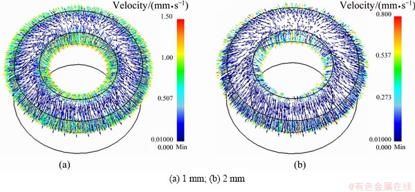
Fig. 6 Distribution of flow velocity of material in different sections parallel to friction surface
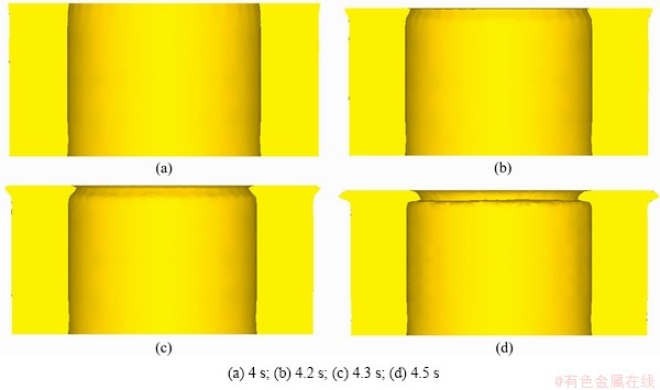
Fig. 7 Flash shapes at different time in CDFW process
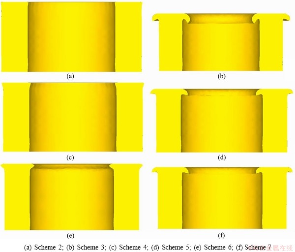
Fig. 8 Flash shapes under different welding schemes
In the CDFW process, when the friction time, the friction pressure or the rotational velocity is relatively small, the dimensions of flashes are small, which results from the low flow velocity of material and then makes the effect of forging of material in and near friction surface not enough. Under this condition, the oxide debris isn��t extruded out of the friction surface and the qualities of welding joints are not good. However, when the dimensions of flashes are too big, too much material with high temperature are extruded out of the friction surface, which is bad for the quality of CDFW joint [8]. Moreover, for the ring structure, the flashes include the inner flash and the outer flash, while the inner flash is difficult to cut out. Because the residual strain in the flashes is relatively large, the cracks easily appear in the inner flash of ring structure in the working process, which may make the region with high residual strain fall out, injure the central rotating axis of component and then make the service life decrease. Therefore, it isn��t good for flashes of CDFW joint to be too small or be too large. For the ring structure researched in this work, the reasonable welding schemes are scheme 5 and scheme 7. During the welding, the large axial pressure is bad for the stability of equipment and then the quality of CDFW joint. Therefore, from the viewpoint of decreasing the axial pressure, scheme 5 is better than scheme 7.
4 Conclusions
1) In the CDFW process of ring structure, the flow velocity of material in the middle region of friction surface is smaller than that near the edge of friction surface. The material near the edge of friction surface flows towards outside of joint, which makes the flashes appear. The increase of friction time, rotational velocity or axial pressure is all good for the increase of dimensions of flashes.
2) Higher rotational velocity, longer friction time and larger friction pressure are beneficial for the increasing of material flow velocity and can make the dimensions of flashes larger. For the ring structure of 45# steel whose inner diameter and outer diameter are respectively 50 mm and 80 mm, the reasonable welding parameters are the friction pressure of 100 MPa, the friction time of 4 s and the rotational velocity of 1600 r/min.
References
[1] SAHIN M, AKATA H E, OZEL K. An experimental study on joining of severe plastic deformed aluminum materials with friction welding method [J]. Materials and Design, 2008, 29(1): 265-274.
[2] Vardhan L S, Madhusudhan R G, MOHANDAS T, MOHANDAS T, KAMARAJ M, MURTY B S. Continuous drive friction welding of Inconel 718 and EN24 dissimilar metal combination [J]. Materials Science and Technology, 2009, 25(7): 851-861.
[3] Sahin M, Akata H E, Gulmez T. Characterization of mechanical properties in AISI 1040 parts welded by friction welding [J]. Materials Characterization, 2007, 58(10): 1033-1038.
[4] LI J M, ZHOU D. Welding process analysis of bimetal valve friction welding [J]. Internal Combustion Engine & Parts, 2009(3): 25-27. (in Chinese)
[5] Satyanarayana V V, Reddy G M, Mohandas T. Continuous drive friction welding studies on AISI 203 Austenitic stainless steel welds [J]. Materials and Manufacturing Process, 2004, 19(3): 487-505.
[6] BETHLEHEM W F. Monitoring of friction welding for quality assurance [J]. Wire World International, 1984, 26(3-4): 43-49.
[7] WU Chuan-song, ZHANG Wen-bin, SHI Lei, CHEN Mao-ai. Visualization and simulation of plastic material flow in friction stir welding of 2024 aluminum alloy plates [J]. Transactions of Nonferrous Metals Society of China, 2012, 22(6): 1445-1451.
[8] Seidel T U, Reynolds A P. Visualization of the material flow in AA2195 friction stir welding using a marker insert technique [J]. Metallurgical and Materials Transactions A, 2001, 32(11): 2879-2884.
[9] LIU Hui-jie, ZHANG Hui-jie. Repair welding process of friction stir welding groove defect [J]. Transactions of Nonferrous Metals Society of China, 2009, 19(3): 563-567.
[10] JI Shu-de, LIU Jian-guang, ZHANG Li-guo, TAO Jun, LIU Zhen-lei. Effect of welding process parameters on material flow behavior of FGH96 alloy in inertia friction welding [J]. Chinese Journal of Mechanical Engineering, 2012, 48(12): 69-74. (in Chinese)
[11] LUO J, YE Y H, XU J J, LUO J Y, CHEN S M, WANG X C, LIU K W. A new mixed-integrated approach to control welded flashes forming process of damping-tube-gland in continuous drive friction welding [J]. Materials and Design, 2009, 30(2): 353-358.
[12] Sathiya P, Aravindan S, Haq A N. Some experimental investigations on friction welded stainless steel joints [J]. Materials and Design, 2008, 29(6): 1099-1109.
[13] LI W Y, WANG F F. Modeling of continuous drive friction welding of mild steel [J]. Materials Science and Engineering A, 2011, 528(18): 5921-5926.
[14] Balasubramanian V, LI Y L, Stotler T, CROMPTON J. A new friction law for the modelling of continuous drive friction welding: applications to 1045 steel welds [J]. Materials and Manufacturing Processes, 1999, 14(6): 845-860.
[15] Zhang Q Z, Zhang L W, Liu W W, ZHANG X G, ZHU W H, QU S. Comparison of 3D and 2D numerical simulation of continuous-drive friction welding process [J]. Transactions of the China Welding Institute, 2006, 27(10): 105-107. (in Chinese)
[16] LI W Y, MA T J, LI J L. Numerical simulation of linear friction welding of titanium alloy: Effects of processing parameters [J]. Materials and Design, 2010, 31(3): 1497-1507.
45#����������Ħ���������в���������Ϊ��ɱ��γɵ�3D��ֵģ��
�����1��������2������÷1���� ��1���� �� 1
1. �������պ����ѧ ���պ��칤��ѧ�������� 110136��
2. ��������ҵ��ѧ ���Ͽ�ѧ�빤��ѧԺ�������� 150001
ժ Ҫ������3D�����������Ԫģ�Ͷ�45#�ֻ��μ���������Ħ������CDFW�������еIJ���������Ϊ��ɱ��γɹ��̽����о����ص����7�ֲ�ͬ�ĺ��ӹ��ղ���Ӱ��Ħ�����渽������������ɱ���̬�Ĺ��ɣ����к��ӹ��ղ�������Ħ��ѹ����Ħ��ʱ������ת�ٶȡ�������������ߵĺ����¶ȷ�ֵ�������ĸ��������Լ����������ѹ�����������Ӻ��ӹ����еIJ��������ٶȡ���CDFW�����У�Ħ�������Ե�����IJ������ͷ���������γɷɱߣ��ҷɱ߳ߴ��������̶�����Ħ��ʱ����ӳ����Լ���ת�ٶȺ�Ħ��ѹ�������Ӷ����ӡ������ھ�50 mm���⾶80 mm��45#�ֻ��μ����Ϻ�����CDFW���ӹ��ղ���Ϊ��Ħ��ѹ��100 MPa��Ħ��ʱ��4 s�Լ���ת�ٶ�1600 r/min.
�ؼ��ʣ���������Ħ������45#�֣��¶ȳ��������������ɱߣ�����Ԫģ�⣻���ӹ��ղ���
(Edited by YANG Bing)
Foundation item: Project (61074090) supported by the National Natural Science Foundation of China
Corresponding author: JI Shu-de; Tel: +86-24-89723472; E-mail: superjsd@163.com
DOI: 10.1016/S1003-6326(12)61756-7
Abstract: The flow behaviour and flash formation of ring component for 45# steel in continuous drive friction welding (CDFW) process were investigated. A 3D thermo-mechanical coupled finite element method was used to conduct this research. Seven welding schemes with different friction pressures, friction times and rotational velocities were carried out. The influences of friction pressure, friction time and rotational velocity on the material flow behaviour at the friction surface and flash formation were analyzed. Research results show that higher peak temperature, larger region with high temperature and larger axial pressure are all good for the increase of material flow velocity. During the CDFW process, the material near the edge of friction surface flows towards the outside of joint, which makes the appearance of flashes. With the increase of rotational velocity, friction time and friction pressure, the dimensions and the bending degree of flashes increase. The reasonable welding parameters of ring structure for 45# steel, whose inner diameter and outer diameter are 50 mm and 80 mm, respectively, are the friction pressure of 100 MPa, the friction time of 4 s and the rotational velocity of 1600 r/min.
