
J. Cent. South Univ. (2012) 19: 1522-1529
DOI: 10.1007/s11771-012-1171-6![]()
Design of motion control of dam safety inspection underwater vehicle
SUN Yu-shan(����ɽ)1, WAN Lei(����)1, GAN Yong(����)2,
WANG Jian-guo(������)3, JIANG Chun-meng(������)4
1. State Key Laboratory of Autonomous Underwater Vehicle (Harbin Engineering University), Harbin 150001, China;
2. Beijing Institute and Control Engineering, Beijing 100190, China;
3. China Ship Development and Design Center, Wuhan 430064, China;
4. Humanities Department, City College of Wuhan University of Science and Technology, Wuhan 430083, China
? Central South University Press and Springer-Verlag Berlin Heidelberg 2012
Abstract:
Plenty of dams in China are in danger while there are few effective methods for underwater dam inspections of hidden problems such as conduits, cracks and inanitions. The dam safety inspection remotely operated vehicle (DSIROV) is designed to solve these problems which can be equipped with many advanced sensors such as acoustical, optical and electrical sensors for underwater dam inspection. A least-square parameter estimation method is utilized to estimate the hydrodynamic coefficients of DSIROV, and a four degree-of-freedom (DOF) simulation system is constructed. The architecture of DSIROV��s motion control system is introduced, which includes hardware and software structures. The hardware based on PC104 BUS, uses AMD ELAN520 as the controller��s embedded CPU and all control modules work in VxWorks real-time operating system. Information flow of the motion system of DSIROV, automatic control of dam scanning and dead-reckoning algorithm for navigation are also discussed. The reliability of DSIROV��s control system can be verified and the control system can fulfill the motion control mission because embankment checking can be demonstrated by the lake trials.
Key words:
1 Introduction
More than 86 000 reservoirs and dams were located in China, and China owns the most reservoirs in the world. Most of the reservoirs and dams were built between 1950s and 1970s [1]. With time going, the aging problem of these dams becomes obvious, and more than one third of the dams are in danger. Dealing with these dams in danger is not only difficult to achieve expectant efficiency but also easy to lead to dam-break. Up to now, there are more than 3 000 reservoir dams broke down, and people��s lives are badly threatened [2]. Therefore, the inspection and maintenance of these dams are very important and should be put more emphases.
Most of the dams built early in China are facing aging problems. Many of the dams have cracks. However, the effective sensors and measure methods were rare when referring to dam inspection such as conduits, cracks and inanition. The traditional dam inspection mainly depends on divers who check the dams with some devices. The traditional method has low efficiency while the danger rate is very high.
Sensors based on the acoustic nondestructive principle could be used for dam inspection, namely, surface and internal parts. The United States, Britain, Canada and Norway have more advanced acoustic sensors than other countries. There are some products available and they can be easily equipped on remotely operated vehicles (ROVs). Researchers in China have carried on some studies on sonar processing and designing. A DSP-based parallel signal processing system was proposed by GUO et al [3]. The key correlative technique was solved by SANG et al [4] and WANG et al [5], and a small chirp sonar and a multi-beam chirp sonar which can be installed easily mounted on ROV was designed. Many experiments verified that the sonar can detect not only the cracks of dams in the surface part but also the conduits and inanition of dams below the water surface [4-6].
Recently, the technology of ROV has been experiencing rapid advancement, and the application of ROV is wide [7-11]. Therefore, the dam safety inspection ROV was designed for the inspection of cracks, crevices and other potential problems of dams, which is developed by Harbin Engineering University and Great Wall Underwater Technology Corp. It is a kind of open-frame ROV and is equipped with many advanced sensors. As the carrier of inspection sensors, the movement of DSIROV should be stable to meet the demands of dam inspection [12]. Underwater dam inspection demo can be seen from Fig. 1 when DSIROV equipped with high frequency imaging sonar and chirp sonar, respectively.

Fig. 1 Underwater dam inspection demo chart: (a) Inspection with imaging sonar; (b) Inspection with chirp sonar
In this work, the design of motion system of DSIROV was proposed. The four degree-of-reedom (DOF) simulation system of ROV was constructed with its hydrodynamic coefficient got by least-square methods and empirical formulas. And the architecture of the ROV motion control system was presented, including hardware and software structures.
2 DSIROV platform
2.1 Dam safety inspection remotely operated vehicle
The dam safety inspection remotely operated vehicle (DSIROV) is a kind of open-frame ROV that is equipped with underwater camera, chirp sonar or high frequency imaging sonar and so on. The DSIROV is requested to move in low speed in dam inspection and should be easy to install different kinds of inspection sensors according to different inspection tasks. Therefore, the open-frame structure is designed to meet these requirements. The DSIROV has six thrusters: two longitudinal thrusters, two vertical thrusters, and two lateral thrusters. Therefore, the roll and trim motions of the DSIROV are always quite small with these manipulative facilities. The overall structure of DSIROV is shown in Fig. 2 while the key specification is listed in Table 1.
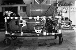
Fig. 2 Overall structure of DSIROV
Table 1 Key specification of DSIROV

2.2 Main technical characteristics
The main technical characteristics are as follows:
1) Structure: open frame;
2) Control style: remote control;
3) Depth rating: 200 m;
4) Velocity: 2 kn in surge; 1 kn in sway; 1 kn in heave;
5) Mass: 293.8 kg (in air);
6) Control range: depth 0-200 m; heading 0��-360��; ranging to dam 0-40 m;
7) Control precision: heading ��1.5��; depth ��0.35 m; ranging to dam ��0.3 m.
3 Simulation system of ROV
3.1 ROV motion control model
The roll and trim motion could be ignored and a four DOF hydrodynamic model could be built up considering the working environment and the open-frame style. Surge, sway, heave and yaw are actively controlled with thrusters, pitch and roll are left uncontrolled due to the passive stability of DSIROV. Based on the rigid-motion theory and Newton-Euler equation, the four DOF hydrodynamic model is constructed as follows:
![]() (1)
(1)
![]() (2)
(2)
![]() (3)
(3)
![]() (4)
(4)
where m is the mass of ROV, RG=(xG, yG, zG) is the position of center of gravity; u, v, w, q and r are the surge, sway, heave, pitch and yaw velocity, respectively.
The gravity, buoyancy of ROV, thrust produced by propeller, hydrodynamics forces and some environment force are composed of the forces and moments (X, Y, Z, N). From the above equations, the movement in the coming moment of ROV can be figured out and the simulation system can be constructed only if we know the current movement of ROV. ROV is always designed to be zero buoyancy, namely, the gravity is equal to buoyancy. The open water thrusts of propellers in different current velocities can be acquired by experiments. Therefore, the thrusts in some current velocities can be obtained by interpolation or curve fitting. The viscous hydrodynamics force of ROV is the function of motion parameters of u, v, w, p, q, r, ![]() ,
,![]() and
and ![]() Hydrodynamic coefficients can be obtained by tank test, system identification or estimation. Finally, the hydrodynamics force of ROV can be obtained:
Hydrodynamic coefficients can be obtained by tank test, system identification or estimation. Finally, the hydrodynamics force of ROV can be obtained:
![]()
![]() (5)
(5)
![]()

![]() (6)
(6)
![]()

![]() (7)
(7)
![]()

![]() (8)
(8)
From above equations, XH, YH and ZH are the surge, sawy and heave hydrodynamics forces, respectively; and NH is the turning moments of ROV; ![]()
![]()
![]()
![]() ��, are first-order or second-order hydrodynamic coefficients of ROV.
��, are first-order or second-order hydrodynamic coefficients of ROV.
3.2 Acquisition of hydrodynamic coefficient
The least-square method is applied to the system identification for the ROV and the turning hydrodynamic coefficients can be got. The hydrodynamic coefficients in other DOF are hard to get from system identification due to some complex ingredients such as the configuration of sensors and the restricted experimental conditions. Therefore, these coefficients can be computed with empirical formulas.
3.2.1 Least-square parameter estimation principle
Suppose that the system to be identified has the same structure as
![]() (9)
(9)
where t is time interval; ![]() is the observation vector;
is the observation vector; ![]() is the vector varying with time;
is the vector varying with time; ![]() is parameter vector.
is parameter vector.
Parameter estimation is a kind of method to get the estimation of parameter vector �� which can satisfy a certain performance by using a group of observation vectors which contain noise. The method adopted in parameter estimation is associated with the character of parameter vector ��. The non-Bayesian or Bayesian methods are adopted if �� is an unknown constant vector. According to Ref. [13-14], the identification model of ROV can be constructed and treated as an unknown constant. Considering hydrodynamic coefficients�� linearity of the identification model, the least-square non-Bayesian method can be adopted for hydrodynamic coefficients identification.
Accordingly, Eq. (9) can be replaced by Eq. (10) only if parameter �� is linear:
![]() (10)
(10)
Least-square estimation ![]() of parameter �� is
of parameter �� is
![]() (11)
(11)
and JLS is quadratic criterion function as
![]() (12)
(12)
The least-square estimation through the derivation of ![]() in Eq. (12) is got in order to find out the definite conditions that makes JLS acquire minimum value:
in Eq. (12) is got in order to find out the definite conditions that makes JLS acquire minimum value:
![]() (13)
(13)
Function ![]() possesses the following characters:
possesses the following characters:
1) It is linear relative to vector y;
2) It is unbiased, namely, ![]() ;
;
3) ![]()
![]()
![]()
![]()
4) ![]() where
where ![]() is the estimation of
is the estimation of ![]() which is got from other linear unbiased estimate method, i.e. least-square estimation is the minimum linear unbiased estimation.
which is got from other linear unbiased estimate method, i.e. least-square estimation is the minimum linear unbiased estimation.
5) Least-square estimation is a consistent and effective estimation.
3.2.2 Hydrodynamic coefficient
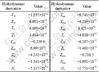
The yaw hydrodynamic coefficients can be got by using least-square method. The hydrodynamic coefficients in other DOF are hard to get from system identification due to some complex ingredients, such as the configuration of sensors and the restricted experimental conditions. Then, these coefficients can be computed based on empirical formulas and figures with ��super-position principle�� and ��equivalent value principle��. So, hydrodynamic coefficients of the ROV is got and presented in Table 2.
Table 2 Non-dimensional hydrodynamic derivatives of DSIROV
According to the low frequency motion model based on Eqs. (1)-(4), the four-order Runge-Kutta method can be used to calculate the ROV��s responsive motion. The time interval in four-order Runge-Kutta method is 0.5 s. Then, the simulation system of DSIROV is built up.
4 DSIROV motion control system
Information through sensors is acquired by the DSIROV��s control system. The control system sends out control commands, keeps each subsystem working in coordination and makes the whole ROV work with expectation.
The core of motion control system of DSIROV is the motion computer based on PC104 BUS and real-time operating system VxWorks. The functions of motion computer include the realization of control algorithm, data acquisition and communicating with external equipment.
The DSIROV��s control system includes the embedded industrial PC (IPC) in bottom layer and PC in surface layer. The IPC is installed in the ROV and communicates with sensors, while the PC is installed in mother ship or on bank. The control algorithm running on the PC is programmed with high-level language. The PC and IPC communicate with each other through optical fiber.
The DSIROV adopts distributing control system composed of surface node and bottom node. The Intel x86 or the compatible CPU system architecture is adopted by the surface node while the PC104 bus computer is adopted by the bottom node, on which the real-time VxWorks embedded operating systems run to achieve remote control ability. The bottom node connects with compass, depth cell and height sonar, ranging measuring sonar, Doppler velocity log (DVL) and pulse width modulation (PWM) drive electrical motor. The configuration of DSIROV��s control system is shown in Fig. 3.
4.1 DSIROV ��s hardware architecture
The main functions of DSIROV��s underwater layer control system are data acquisition, control algorithm, force allocation, commands sending and communicating with surface layer control system. It includes getting attitude information from compass, velocity from DVL with eight channel serial board, depth and leakage information from A/D board, sending analogue voltage commands to thrusters with D/A board and getting target instructions from surface layer control computer. The hardware architecture of DSIROV motion control system is shown in Fig. 4.
The motion control system of ROV is based on multi-board embedded system with PC104 BUS. It contains CPU board integrated ELAN520 processor, eight-channel serial board, A/D board, D/A board and power board.
The AMD CPU is used as the core module while an ELAN520 chip with 133 MHz master frequency is also adopted. The EMM-8M-XT is selected as the serial board that is developed by Diamond Company. Two 16 554 asynchronous serial communicating chips and a 64-byte buffer are integrated. The DMM-16-AT and RMM-1612-XT used as the A/D and D/A module respectively are also developed by Diamond Company.

Fig. 3 System configuration of DSIROV
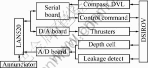
Fig. 4 Hardware architecture of DSIROV motion control system
4.2 DSIROV software architecture
4.2.1 Control software architecture
As to the surface control computer, the VC++6.0 is chosen as the program language to develop highly efficient man-machine interactive programs. The module design method is preferred in order to make the debugging and modification convenient. The control software architecture mainly includes control algorithm, data processing, force allocation, sensor information acquisition, communication, displaying, and hydro- dynamics modules.
The information flow of motion control system is shown in Fig. 5. Part A is the control algorithm module that mainly adopts some algorithms to acquire ROV��s expected thrust, and realizes the motion control of ROV. Part B is the data process module. It can be divided into two parts: data preprocess and data fusion. Data preprocess includes rejecting outliers and data smooth. After data pretreatment, the data filtering and data fusion are required. This module mainly provides high quality data for the control algorithm module. Part C is the force allocation module that conducts force allocation algorithm and sends control commands to thrusters. Part D is the hardware architecture, and it is the most important component of the basic motion control system.
4.2.2 Basic motion control algorithm
Recently, there are many control algorithms studied, and each control method has its advantages and disadvantages.
The neural network control and fuzzy control are the main control methods because of the strong nonlinear character of ROV. DSIROV needs installing different sonar equipment, therefore, the mathematic model is hard to get. An easy and practical control method, s-plane control, based on fuzzy control ideology is adopted here:
![]() (14)
(14)
where ei and ![]() are the input information of the i-th freedom control (deviation and deviation rate, using normalization process); ui is the output of the i-th freedom control; ki1 and ki2 are the control parameters of deviation and deviation rate of the i-th freedom, respectively; fi is the expecting force value in that freedom; Ki is the maximal thrust (moment) that can be provided in that freedom; ?ui is the fixed disturb force (normalization process) that can be acquired with adaptive method. From many experiments, the conclusion that the adaptive item will always result in the slow response and the stable error can be got. Therefore, the static payload us is taken into account.
are the input information of the i-th freedom control (deviation and deviation rate, using normalization process); ui is the output of the i-th freedom control; ki1 and ki2 are the control parameters of deviation and deviation rate of the i-th freedom, respectively; fi is the expecting force value in that freedom; Ki is the maximal thrust (moment) that can be provided in that freedom; ?ui is the fixed disturb force (normalization process) that can be acquired with adaptive method. From many experiments, the conclusion that the adaptive item will always result in the slow response and the stable error can be got. Therefore, the static payload us is taken into account.

Fig. 5 Information flow of motion control system
The control is different from the PD control, and this control method reflects the nonlinearity that makes it have better fitting effect. Compared with fuzzy control, it has better smooth control output, and it needs less experience, and less parameters are needed to adjust.
4.2.3 Automatic dam-scanning control
The main purpose of DSIROV is to detect the dam with its vision systems, and the most important facet is to make the ROV keep a certain distance from the dam while the yaw and dam are perpendicular. The dam is scanned from the above to the below. The yaw should be kept at a certain angle and the whole trajectory should be parallel to the dam when scanning.
Because the motion between the vertical freedom and the longitudinal freedom is not consistent, namely, the vertical motion is slow while the longitudinal motion is relatively fast, the motion ability between the vertical and longitudinal should be taken into account.
The most direct response of ROV��s motion ability is the maximal motion displacement and velocity in each freedom. In order to keep the consistence between the vertical motion and the longitudinal motion, the most direct method is to compare the relation among location deviation, the maximal motion displacement and the maximal motion velocity in these two freedoms. The deviation of the control input from comparing the ratio among location deviation r, the maximal motion displacement and the maximal motion velocity are confirmed in this work.
The following algorithm can be deduced:
If ![]() then
then
 (15)
(15)
If ![]() then
then
 (16)
(16)
where ex,max, eu,max, ez,max and ew,max are the maximal motion displacement and velocity of longitudinal and vertical within a time interval, respectively; ![]() and
and ![]() are the location deviations of s-plane control algorithm in the longitudinal and vertical freedoms, respectively, namely ei in Eq. (14); ex and ez are location deviations in longitudinal and vertical freedoms, respectively;
are the location deviations of s-plane control algorithm in the longitudinal and vertical freedoms, respectively, namely ei in Eq. (14); ex and ez are location deviations in longitudinal and vertical freedoms, respectively; ![]() and
and ![]() are longitudinal and vertical draught distances, respectively, and the definition is
are longitudinal and vertical draught distances, respectively, and the definition is
![]()
The input ![]() of control algorithm not only takes the maximal drought distance in each freedom into account, namely, the greatest motion ability in each freedom, but also considers the ratio among location deviation, the maximal motion displacement and the maximal motion velocity so that it can guarantee the consistence in the vertical and longitudinal freedoms.
of control algorithm not only takes the maximal drought distance in each freedom into account, namely, the greatest motion ability in each freedom, but also considers the ratio among location deviation, the maximal motion displacement and the maximal motion velocity so that it can guarantee the consistence in the vertical and longitudinal freedoms.
4.2.4 Dead-reckoning navigation
The current position of DSIROV should be kept though it does not need precision position control for multi-DOF. The position information of ROV can be obtained by a navigation system based on dead- reckoning algorithm [15]. The strong tracking Kalman filter is applied which possesses adaptability to uncertainties of modeling system, smaller sensitivity to noise and statistic characteristics of initial value, and tracking ability to saltation status. The dynamic system model can be described as
![]() (17)
(17)
 (18)
(18)
where
![]()
![]()


W(k) and V(k) are white gauss noises; xe(k) and xn(k) are the eastern velocity and western velocity of ROV at time k, respectively; T is the sampling period, namely control time interval.
5 Experiment results
Lake trials were conducted in Lianhua River located in Heilongjiang Province in 2004. The dam of Lianhua River was made of concrete and extended at 45�� along with the depth of water. Generating electricity and irrigation were the main purpose of dam. There maybe exist cracks and some other problems with the dam because of the concussion and corrosion. Therefore, inspiration of the dam was very urgent.
Two kinds of back-check for the dam were conducted in this experiment. One was photographing the dam with an underwater camera at a short ranging, and the yaw of ROV should be perpendicular with the main body of dam in this case. The other was letting the ROV keep a distance from the main body of the dam, and then using chirp sonar to do multi-dot vertical scanning. The concrete scanning approach was keeping a certain distance and direction at a location first. So, the yaw of ROV was perpendicular with the main body of dam. Then, let the ROV scan the dam along vertical direction while keep the distance and yaw. After finishing a vertical scanning, the ROV was adjusted to move to the next expected location while keeping the yaw and dam parallel, and the process should do it again. Therefore, there were many vertical scans in a scanning process.
The information of depth, yaw and distance between the ROV and dam during a dam-scanning process can be seen in Figs. 6-to. The distance information was got from the range sonar, and its scan range is 15��. Figures 9 and 10 show the longitudinal and transverse position information of the earth-fixed frame in a vertical dam-scanning process, which was got by dead reckoning navigation. From the experiment results, the depth control stable error is about ��0.3 m, the yaw control stable error is about ��5�� (because of the dam interception river, the scream was very disordered) and the longitudinal control stable error is about ��1 m (the distance referred was 5 m between the vehicle and the dam). There were 10 m bias in the longitudinal and 2 m bias in the transverse with dead-reckoning navigation within 18 min, but all these could be accepted in dam-scan process.
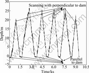
Fig. 6 Depth information of dam-scanning

Fig. 7 Yaw information of dam-scanning
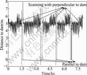
Fig. 8 Distance information of dam-scanning

Fig. 9 Longitudinal position information
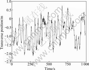
Fig. 10 Transverse position information
6 Conclusions
1) The hydrodynamic coefficients of DSIROV are obtained by identification or estimation, and based on the principles of rigid-motion and Newton-Euler equation of motion, the four DOF motion simulation system is constructed.
2) Motion control system architecture of DSIROV is constructed. The AMD ELAN520 is used as the controller��s embedded CPU, which is based on PC104 BUS and works under VxWorks system. Automatic control of dam-scanning and dead-reckoning algorithm for navigation are introduced, which can guarantee the consistence in the vertical and longitudinal freedoms.
3) Experimental results demonstrate that DSIROV��s control system is safe, reliable and can fulfill the motion control mission for underwater embankment check.
References
[1] DONG Bing-jiang, ZHANG Xiao-feng. Reservoir dam break flow and sediment simulation [C]// 2009 Asia-Pacific Power and Energy Engineering Conference. Wuhan, China, 2009: 28-31.
[2] WANG Xiao-ling, ZHOU Zheng-yin, SUN Rui-rui, ZHOU Sha-sha. Fuzzy hierarchy comprehensive evaluation on dam-break risk analysis [J]. Advanced Materials Research, 2012, 383-390: 2151- 2155.
[3] GUO Yuan-xi, SANG En-fang, GAO Peng, WANG Ji-sheng. Design of an extensible universal sonar signal processing system in parallel [J]. Journal of Naval university of Engineering, 2007, 19(3): 31-34. (in Chinese)
[4] SANG En-fang, WANG Ji-sheng, QIAO Gang, GAO Yun-tao. Design and implementation of chirp sonar for small carrier [J]. Journal of Harbin Engineering University, 2006, 27(5): 737-741. (in Chinese)
[5] WANG Ji-sheng, GUO Yun-xi, QIAO Gang. Experimentation and investigation of chirp sonar for dam inspection [J]. Journal of Naval University of Engineering, 2007, 19(4): 33-37. (in Chinese)
[6] WANG Xiao-feng, SANG En-fang, BIAN Hong-yu. Some advances of underwater acoustic imaging research for UUV [C]// 2010 IEEE International Conference on Information and Automation. Harbin, China: IEEE, 2010: 2348-2351.
[7] CHIN C S, LAU M W S, LOW E. Supervisory cascaded controller design: Experiment test on a remotely operated vehicle [J]. Journal of Mechanical Engineering Science, 2011, 225(C3): 584-603.
[8] FLETCHER B, BOWEN A, YOERGER D R, WHITCOMB L L. Journey to the challenger deep: 50 years later with the Nereus hybrid remotely operated vehicle [J]. Marine Technology Society Journal, 2009, 43(5): 65-76.
[9] MANECIUS S J, SUBRAMANIAN R R, SATHIANARAYANAN A N, HARIKRISHNAN D, JAYAKUMAR G, MUTHUKUMARAN V K, MURUGESAN D, CHANDRESEKARAN M, ELANGOVAN E, PRAKASH D, VADIVELAN V, RADHAKRISHNAN A, RAMESH M, RAMADASS S, ATMANAND G A, SUKONKIN S, ALEXEY A. Technology tool for deep ocean exploration-Remotely operated vehicle [C]// Proceedings of the International Offshore and Polar Engineering Conference. Beijing, China, 2010: 206-212.
[10] ZHU Ke-qiang, ZHU Hai-yang, ZHANG Yu-song, GAO Jie, MIAO Guo-ping. A multi-body space-coupled motion simulation for a deep-sea tethered remotely operated vehicle [J]. Journal of Hydrodynamics, 2008, 20(2): 210-215.
[11] YOSHIDA H, ISHIBASHI S, WATANABE Y, INOUE T, TAHARA J, SAWA T, OSAWA H. The ABISMO mud and water sampling ROV for surveys at 11,000 m depth [J]. Marine Technology Society Journal, 2009, 43(5): 87-96.
[12] SUN Yu-shan, PANG Yong-jie, WAN Lei, QIN Zai-bai. Design plan of GDROV for the underwater inspecting robot of dikes [J]. Ship & Ocean Engineering, 2006, 35(1): 84-86. (in Chinese)
[13] AVILA J P J, ADAMOWSKI J C, MARUYAMA N, TAKASE F K, SAITO M. Modeling and identification of an open-frame underwater vehicle: The yaw motion dynamics [J]. Journal of Intelligent and Robotic Systems: Theory and Applications, 2011, 66(1): 37-56.
[14] YU Hua-nan. Research on identification and control of an open- frame ROV [D]. Harbin: Harbin Engineering University (College of Shipbuilding Engineering), 2003: 16-20. (in Chinese)
[15] SUN Yu-shan, LIANG Xiao, WAN Lei, PANG Yong-jie. Design of the embedded navigation system of autonomous underwater vehicle based on the VxWorks [C]// 2007 IEEE International Conference on Control and Automation. Guanzhou, China, 2007: 2919-2924.
(Edited by DENG L��-xiang)
Foundation item: Project(20100480964) supported by China Postdoctoral Science Foundation; Projects(2002AA420090, 2008AA092301) supported by the National High Technology Research and Development Program of China
Received date: 2011-03-11; Accepted date: 2012-02-24
Corresponding author: SUN Yu-shan, Associate Professor, PhD; Tel: +86-451-82568056; E-mail: sunyushan@hrbeu.edu.cn
Abstract: Plenty of dams in China are in danger while there are few effective methods for underwater dam inspections of hidden problems such as conduits, cracks and inanitions. The dam safety inspection remotely operated vehicle (DSIROV) is designed to solve these problems which can be equipped with many advanced sensors such as acoustical, optical and electrical sensors for underwater dam inspection. A least-square parameter estimation method is utilized to estimate the hydrodynamic coefficients of DSIROV, and a four degree-of-freedom (DOF) simulation system is constructed. The architecture of DSIROV��s motion control system is introduced, which includes hardware and software structures. The hardware based on PC104 BUS, uses AMD ELAN520 as the controller��s embedded CPU and all control modules work in VxWorks real-time operating system. Information flow of the motion system of DSIROV, automatic control of dam scanning and dead-reckoning algorithm for navigation are also discussed. The reliability of DSIROV��s control system can be verified and the control system can fulfill the motion control mission because embankment checking can be demonstrated by the lake trials.
