
J. Cent. South Univ. Technol. (2011) 18: 6-15
DOI: 10.1007/s11771-011-0651-4
![]()
Morphology and growth of porous anodic oxide films on Ti-10V-2Fe-3Al in neutral tartrate solution
YI Jun-lan(����), LIU Jian-hua(������), LI Song-mei(����÷),
YU Mei(����), WU Guo-long(�����), WU Liang(����)
School of Materials Science and Engineering, Beihang University, Beijing 100191, China
? Central South University Press and Springer-Verlag Berlin Heidelberg 2011
Abstract:
Porous anodic oxide films were fabricated galvanostatically on titanium alloy Ti-10V-2Fe-3Al in ammonium tartrate solution with different anodizing time. Scanning electron microscopy (SEM) and field emission scanning electron microscopy (FE-SEM) were used to investigate the morphology evolution of the anodic oxide film. It is shown that above the breakdown voltage, oxygen is generated with the occurrence of drums morphology. These drums grow and extrude, which yields the compression stress. Subsequently, microcracks are generated. With continuous anodizing, porous oxides form at the microcracks. Those oxides grow and connect to each other, finally replace the microcrack morphology. The depth profile of the anodic oxide film formed at 1 800 s was examined by Auger electron spectroscopy (AES). It is found that the film is divided into three layers according to the molar fractions of elements. The outer layer is incorporated by carbon, which may come from electrolyte solution. The thickness of the outer layer is approximately 0.2-0.3 ��m. The molar fractions of elements in the intermediate layer are extraordinarily stable, while those in the inner layer vary significantly with sputtering depth. The thicknesses of the intermediate layer and the inner layer are 2 ��m and 1.0- 1.5 ��m, respectively. Moreover, the growth mechanism of porous anodic oxide films in neutral tartrate solution was proposed.
Key words:
titanium alloy; porous anodic oxide films; morphology evolution; growth mechanism��
1 Introduction
Anodic oxidation is a widely used surface treatment to form protective oxide films on titanium and its alloys [1-5]. Generally, the films are almost several tens of nanometers [6] to about 1 ��m [7] in thickness. Such films are transparent and the colors of the films have been explained by the multiple-beam interference theory [8]. The interest of researchers was attracted again to the process of anodic oxidation a few years ago, when thick and porous titania films were formed [9]. Recently, it has been realized that electrochemical oxidation in fluorine- containing solution is a simple and straightforward method to prepare thick and porous titania films on titanium substrates [10].
In 1991, ZWILLING et al [9] reported the porous surface of titania films formed electrochemically in fluorinated electrolyte by anodization. A decade later, GONG et al [11] first reported the formation of porous titania via anodic oxidation of titanium in a hydrofluoric acid electrolyte. By varying pH and electrolyte concentration, they achieved a 6.4 ��m-thick film using a fluoride solution of pH 5.5 [12]. ZHU et al [13] used hydrofluoric acid as the pretreatment reagent and prepared a 5-7 ��m-thick film at high voltage. Recently, SCHMUKI et al [14-15] fabricated a porous anodic oxide film with a thickness of 2.5-7.0 ��m in fluoride- based bath. However, hydrofluoric acid and fluoride are harmful to the environment owing to their high toxicity and complexity of their disposal process. Not surprisingly, environmentally friendly anodic oxidation process became the focus.
The type of electrolyte used and electric conditions applied can affect the surface morphology, chemical composition, and crystalline structure of the films formed by anodic oxidation [9, 16-19]. In our previous work [20], an environmentally friendly anodic oxidation method was presented. At a high pulse current density (10 A/dm2), non-transparent, thick and porous oxide films were fabricated in neutral tartrate solution without using hydrofluoric acid or fluoride. According to our results, the surface morphology and crystalline structure of the films formed under these conditions were quite different from those of the films formed in fluoride-based bath. Significantly, the surface and cross section morphologies of anodic oxide film change with anodizing time. Therefore, the first goal of this work was to observe the morphology evolution of the anodic oxide film. Standard methods (Such as SEM, FE-SEM and AES) were used to characterize the anodic oxide film.
The growth mechanism of porous anodic oxide film on titanium by electrochemical methods attracts more and more attention. It is well known that anodic oxidation treatments of aluminum can be classified into three categories with respect to the formation of pits, pores, or a barrier layer [21]. So-called porous titania corresponds to the pitting regime of aluminum where pores are created due to the dielectric breakdown of titania or alumina. The breakdown of anodic titania has been defined by oxygen evolution associated with crystallization [22]. CHOI et al [21] divided the growth process of porous titania into three steps: 1) the thickness of a non-porous, barrier titania grows larger with increasing anodizing voltage; 2) breakdown of the barrier oxide film occurs and new pores in/between crystallites are formed; 3) the areas of electrical breakdown of the oxide are immediately covered with titanium oxide again. LU et al [23] reported that the growth of the porous oxides is suggested to be associated with loss of film species at the film/electrolyte interface at the base of pores, with new oxide forming exclusively at the metal/film interface by inward migration of O2- ions. The growth mechanism of porous anodic oxide films in neutral tartrate solution is proposed in this work.
2 Experimental
2.1 Specimen preparation
A Ti-10V-2Fe-3Al forged block was cut into sheets of 60 mm��30 mm��3 mm. The nominal composition of Ti-10V-2Fe-3Al is given in Table 1. Each sample was abraded with silicon carbide (SiC) paper of successive grades from 300 to 1 000 grit, followed by rinsing with acetone and deionized water successively and finally dried in air.
Table 1 Nominal composition of Ti-10V-2Fe-3Al (mass fraction, %)
![]()
Anodic oxidation was carried out in a cell with a thermostat water bath and a magnetic stirring apparatus. The sample was used as the anode and a 1Cr18Ni9Ti stainless steel plate was used as the cathode in an electrolytic cell. The anode surface was less than 50% that of the cathode. The electrolyte used was an aqueous solution of ammonium tartrate, which was prepared from analytical grade chemicals and deionized water. The sample suspended by a copper wire was partially immersed into the electrolyte, which ensured that the copper wire did not contact with the electrolyte. The area under the water was calculated before anodic oxidation for setting the current density.
Anodic oxidation was performed using a pulse galvanostatic power supply WMY-IV. The fabrication conditions were studied in detail previously [20]. Test conditions varied in terms of anodizing time, ranging from 10 to 1 800 s, as presented in Table 2. Other main anodizing parameters were fixed and are shown in Table 3.
Table 2 List of anodizing time applied in tests
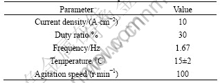
Table 3 Parameters of fabrication process
2.2 Specimen characterization
The morphologies of the surfaces and cross sections of specimens were observed with a lower magnification SEM (FEI-Quanta600D8032) and a higher magnification FE-SEM (Hitachi S-4800). The depth profile of the anodic oxide film formed at 1 800 s was examined by AES (ULVAC-PHI 700).
3 Results
3.1 Evolution of voltage-time response
The color and thickness of anodic oxide film depend on the anodic forming voltage. Therefore, voltage-time responses were investigated during anodizing. Voltage-time responses for anodic oxidation of specimen at different anodizing time are highly reproducible (as shown in Fig.1). From the commencement of the anodizing, the voltage increases approximately linearly with time to 80 V at 1.33 V/s. Subsequently, reduced slope of approximately 0.21 V/s to the final anodizing voltage of 230 V is revealed. The film is transparent before 300 s. The film becomes non- transparent visually after 300 s at 126 V, with a variation in the voltage of no more than a few volts between repeated measurements. The film formed at 1 800 s is uniformly non-transparent yellow.
3.2 Evolution of surface morphology
Lower magnification scanning electron micrographs disclose a unique growth behavior of porous anodic
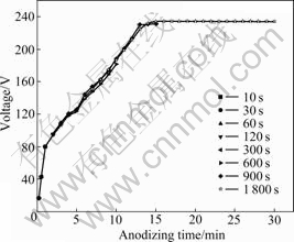
Fig.1 Voltage-time responses for anodic oxidation of specimen at different anodizing time
oxide films, as represented in Fig.2. The surface morphology of the specimen varies with anodizing time. The SEM micrographs of specimens obtained before 120 s (Figs.2(a) and (b)) show even surface with some scratches generated by grinding. The substrate-like appearance of the film changes from 120 to 300 s, with the occurrence of drums (refer to the materials marked in Fig.2(c)). The drums grow and spread to a larger region, and distribute almost uniformly with longer anodizing time (Fig.2(d)). At 600 s, there are some regions which are still not covered by the drums yet (refer to the regions marked in Fig.2(d)). With continuously increasing anodizing time to 900 and 1 800 s (Figs.2(e) and (f)), the drums cover the surface evenly and connect to each other.
Fig.3 presents higher magnification field emission
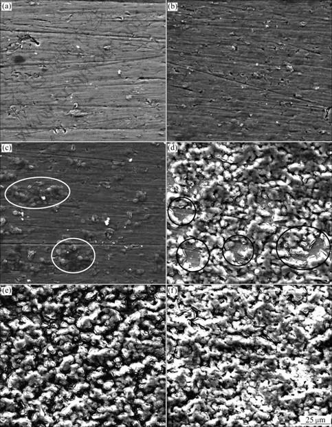
Fig.2 Lower magnification scanning electron micrographs of anodic oxide films formed on Ti-10V-2Fe-3Al with different anodizing time: (a) 10-60 s; (b) 120 s; (c) 300 s; (d) 600 s; (e) 900 s; (f) 1 800 s
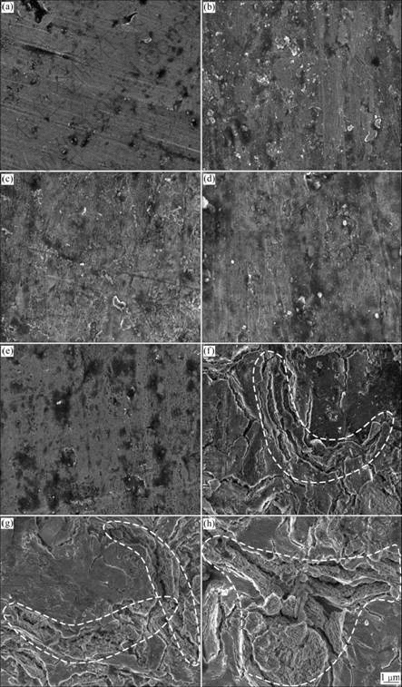
Fig.3 Higher magnification field emission scanning electron micrographs of anodic oxide films formed on Ti-10V-2Fe-3Al with different anodizing time: (a) 10 s; (b) 30 s; (c) 60 s; (d) 120 s; (e) 300 s; (f) 600 s; (g) 900 s; (h) 1 800 s
scanning electron micrographs of porous anodic oxide films on Ti-10V-2Fe-3Al alloy under the present anodizing conditions. At 10 s, the substrate morphology is presented in Fig.3(a) with some grinding scratches and machining defects. After 10 s, the barrier layer is formed on the surface, as shown in Figs.3(b)-(d). It is obvious that there are several electric breakdown sites of the barrier layer on the surface at 300 s (Fig.3(e)). Breakdown occurs accompanied by gas evolution, which is associated with the drums morphology observed in Fig.2(c). After 300 s, drums (shown in Fig.2(d)) grow and spread. The compression stress is generated by drums extruding each other. Therefore, microcracks (as shown in Fig.3(f)) are initiated at the ridges of the drums. With continuously increasing the anodizing time to 900-1 800 s, porous oxides form at the microcracks. The oxides grow and connect to each other (as shown in Figs.3(g) and (h)), finally replace the former microcracks morphology.
3.3 Evolution of cross section morphology
Figs.4 and 5 show the cross section micrographs of the anodic oxide films formed on Ti-10V-2Fe-3Al under the present anodizing conditions. The cross section micrographs of specimens obtained before 120 s exhibit barrier layer with thickness increasing, as shown in Figs.4(a)-(d) and Figs.5(a)-(d). The porous layer begins to form after 300 s, with the occurrence of microcracks (as shown in Fig.5(e)) due to the gas evolution. It is obvious that the cross section of the porous layer exhibits
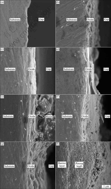
Fig.4 Lower magnification cross section micrographs of anodic oxide films formed on Ti-10V-2Fe-3Al with different anodizing time: (a) 10 s; (b) 30 s; (c) 60 s; (d) 120 s; (e) 300 s; (f) 600 s; (g) 900 s; (h) 1 800 s
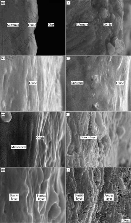
Fig.5 Higher magnification cross section micrographs of anodic oxide films formed on Ti-10V-2Fe-3Al with different anodizing time: (a) 10 s; (b) 30 s; (c) 60 s; (d) 120 s; (e) 300 s; (f) 600 s; (g) 900 s; (h) 1 800 s
a laminated structure (as shown in Figs.5(e)-(g)), which is related to the ridges of drums. With continuously increasing the anodizing time, the porous oxides grow and connect to each other, with small inlaid particles and pores (as shown in Fig.5(b)). The thicknesses of anodic oxide films formed at different anodizing time measured from the cross section micrographs are shown in Table 4.
3.4 Depth profile of anodic oxide film
The depth profile of the anodic oxide film formed on specimen at 1 800 s is obtained by using AES, as shown in Fig.6. It is found that anodic oxide film is divided into three layers according to the molar fractions of elements. The outer layer is incorporated by carbon, which may come from electrolyte solution. The thickness
Table 4 Thickness of anodic oxide film
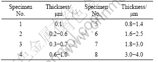
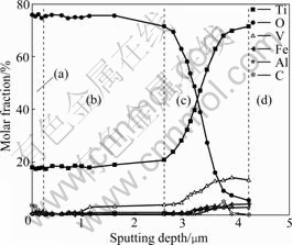
Fig.6 Depth profile of anodic oxide film formed on specimen at 1 800 s: (a) Outer layer; (b) Intermediate layer; (c) Inner layer; (d) Substrate
of outer layer is approximately 0.2-0.3 ��m. The molar fractions of elements of the intermediate layer are extraordinary stable (the variation of vanadium can be neglected due to the quite small content of vanadium in this layer). The thickness of the intermediate layer is approximately 2 ��m. The molar fractions of elements in the inner layer vary significantly with sputtering depth. Oxygen content decreases rapidly and correspondingly titanium content increases quickly. Vanadium increases gradually, while aluminum and ferrous contents are almost unchanged with sputtering depth. The thickness of the inner layer is approximately 1-1.5 ��m.
4 Discussion
4.1 Relationship among voltage, morphology, com- position and microstructure
The linear voltage increase at the beginning of anodizing indicates the growth of the barrier layer of anodic oxide film without the oxygen generation. Although there might be substantial differences in the mechanisms of anodizing for different alloys, common requirements in most of them are inward migration of oxygen anion species and outward migration of metal cation species. The barrier layer of anodic oxide film on titanium alloy Ti-10V-2Fe-3Al is also formed by the inward migration of oxygen anions and the outward of migration metal cations (including titanium, vanadium and other metal cations). The depth profile obtained by AES demonstrates the existence of alloying elements in the barrier layer of anodic oxide film. Reduced slope of anodizing forming voltage observed after 80 V, as well as the drum morphology observed after 120 s are associated with the electronic breakdown and gas evolution. The latter is macroscopically observed during the experiment. In addition, the drum morphology observed can be related to macroscopic non-transparent appearance. Such a difference in morphology is probably related to the composition and structure of the oxides developed. According to the X-ray photoelectron spectroscopy (XPS) results in the previous work [20], TiO2 is contained in the anodic oxide films, whereas the content of C in the anodic oxide film on the surface is extraordinarily high (above 50 %). High resolution XPS spectrum of the C 1s region shows the existence of typical functional groups of ammonium tartrate molecule, which means that ammonium tartrate may adsorb in the pores of the films and deposit after the water volatilization, or be involved in the film formation reactions. From the depth profile of the anodic oxide film obtained by AES, the surface layer after sputtering still contains a small amount of carbon (3%-5%), which shows the thickness of the carbon incorporated layer. Under the present conditions, the crystallization and associated oxygen generation may occur more readily due to high current density (10 A/dm2). The crystalline oxide provides an electron conducting path under the high electric field, enabling the oxygen generation within the anodic oxide [22]. However, from the X-ray diffraction (XRD) results in the previous work [20], the films formed on the titanium alloy Ti-10V-2Fe-3Al are practically amorphous, with very small amount of crystalline oxide as indicated by Raman spectroscopy. The crystallization of amorphous titania is impeded by the incorporation of tartrate species. Meanwhile, the incorporated alloying elements also stabilize the amorphous oxide.
4.2 Film growth mechanism
By combining the above evidences, the growth model of porous anodic oxide film on titanium alloy Ti-10V-2Fe-3Al in neutral tartrate solution is proposed in Fig.7. Anodizing procedure is divided into four steps.
Firstly, oxygen anion species transport inward and metal cation species migrate outward assisted by the electron field. The relationship between the anodic current and the electric field strength across the anodic oxide film is described by the following equation:
I=Aexp(BE) (1)
where I is the ionic current. A and B are the electrolytic constants. E is the electric field strength and can be
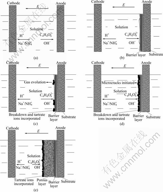
Fig.7 Growth model of porous anodic oxide films on titanium alloy Ti-10V-2Fe-3Al in neutral electrolyte: (a) Original morphology of substrate/solution interface; (b) Formation of barrier layer at substrate/ solution interface; (c) Breakdown, gas evolution and tartrate ions incorporation into anodic oxide film; (d) Growth of tartrate ions incorporated layer and microcracks initiation; (e) Formation of porous layer at tartrate ions incorporated layer/barrier layer interface
replaced by V/��. V is the anodizing forming voltage and �� refers to the anodic oxide thickness. During galvanostatic anodizing, in order to maintain the given current density, constant field strength across the previously formed barrier film is required. As a consequence, when the oxide thickness increases with time at constant current density, the voltage across the oxide film must increase in order to maintain the field strength and the current density. The growth mechanism of titania films involves electronation at counter electrode (as shown in Eq.(2)), electrochemically driven diffusion of anions (such as oxygen anions) and cations (titanium, vanadium and other metal cations) in the films, electrochemical reactions at the metal/electrolyte interface (as shown in Eqs.(3)-(5), same as Ref.[24]). Very few amounts of alloy elements may participate to form some suboxide (as shown in Eqs.(6)-(7)).
2H++2e=H2 (2)
Ti+O2-=TiO+2e (3)
2TiO+O2-=Ti2O3+2e (4)
Ti2O3+O2-=2TiO2+2e (5)
V+O2-=VO+2e (6)
Fe+O2-=FeO+2e (7)
Secondly, anodizing forming voltage achieves the breakdown voltage. The evolution of oxygen (as shown in Eq.(8)) generates surface defects and electron transport channels. The latter dramatically increases the electronic field, simultaneously changes the Gibbs free energy of the surface and accelerates tartrate anions adsorption or precipitation at these breakdown sites on the barrier layer/electrolyte interface:
2O2-=O2+4e (8)
Thirdly, the absorption or precipitation accelerates the nucleation and growth of oxides at these surface defects and electron transport channels on the tartrate ions incorporated layer/barrier layer interface. The oxides exhibit drum morphology, which are formed according to the morphology of the oxygen bubbles evolved at the interface. Then, the drums grow and extrude, which generates the compression stress and microcracks subsequently.
Fourthly, the high current density at the microcracks promotes the quadratic nucleation of oxides inside these microcracks. The oxides grow and connect to each other, with small inlaid particles and pores. Therefore, with continuous anodizing, porous oxides form at the microcracks, and finally replace the former microcracks morphology. The absorbent or precipitate contains tartrate anions. These tartrate anions react with titanium cation ions (as shown in Eq.(9)) and generate complex of titanium tartrate, which accelerates the migration of titanium ions. Titanium cation at the tartrate anions incorporated layer/barrier layer interface achieves its saturated concentration. The migration of titanium cation is not the limitation of the film growth. Oxygen anions transport across the tartrate anions incorporated layer and react with the intermediate complex of titanium tartrate (as presented in Eq.(10)), which is the rate-controlling step of the film growth. This model can well explain the phenomena that the thickness of the porous layer increases with time, whereas the composition of the intermediate layer of porous anodic oxide film is extraordinary stable.
Ti4++2(C4H6O6)2-=Ti��(C4H4O6)2 (9)
Ti��(C4H4O6)2+2O2-=TiO2+2(C4H6O6)2- (10)
5 Conclusions
1) Porous anodic oxide films on titanium alloy Ti-10V-2Fe-3Al are fabricated in ammonium tartrate solution at 10 A/dm2 with different anodizing time. The slope of anodizing forming voltage with time decreases suddenly after 80 V.
2) After the breakdown voltage (~80 V), oxygen is generated with the occurrence of drums morphology. These drums grow and extrude, which yields the compression stress. Subsequently, microcracks are generated. With continuous anodizing, porous oxides form at these microcracks. And porous oxides grow and connect to each other with small inlaid particles and pores.
3) Anodic oxide film is divided into three layers according to the molar fractions of elements. The outer layer is incorporated by carbon, which may come from electrolyte solution. The thickness of the outer layer is approximately 0.2-0.3 ��m. The molar fractions of elements in the intermediate layer are extraordinarily stable, while those in the inner layer vary significantly with the sputtering depth. The thicknesses of the intermediate layer and the inner layer are 2 ��m and 1-1.5��m, respectively.
4) Titanium cations migration is not the limitation of the film growth due to the generation of intermediate complex of titanium tartrate. Oxygen anions transport across the carbon incorporated layer and react with the intermediate complex of titanium tartrate, which is the rate-controlling step of the film growth.
References
[1] ALADJEM A. Anodic oxidation of titanium and its alloys [J]. J Mater Sci, 1973, 8: 688-704.
[2] POPA M V, VASILESCU E, DROB P, ANGHEL M, VASILESCU C, ROSCA I M, LOPEZ A S. Anodic passivity of some titanium base alloys in aggressive environments [J]. Mater Corros, 2002, 53: 51-55.
[3] FOVET Y, GAL J Y, CHEMLA F T. Influence of pH and fluoride concentration on titanium passivating layer stability of titanium dioxide [J]. Talanta, 2001, 53: 1053-1063.
[4] FENG B, CHEN J Y, QI S K, HE L, ZHAO J Z, ZHANG X D. Characterization of surface oxide films on titanium and bioactivity [J]. J Mater Sci Mater Med, 2002, 13: 457-464.
[5] VELTEN D, BIEHL V, AUBERTIN F, VALESKE B, POSSART W, BREME J. Preparation of TiO2 layers on cp-Ti and Ti6Al4V by thermal and anodic oxidation and by sol-gel coating techniques and their characterization [J]. J Biomed Mater Res, 2002, 59: 18-28.
[6] SUL Y T, JOHANSSON C B, JEONG Y, ALBREKTSSON T. The electrochemical oxide growth behavior on titanium in acid and alkaline electrolytes [J]. Med Eng Phys, 2001, 23: 329-346.
[7] SUL Y T, JOHANSSON C B, PETRONIS S, KROZER A, JEONG Y, WENNERBERG A, ALBREKTSSON T. Characteristics of the surface oxides on turned and electrochemically oxidized pure titanium implants up to dielectric breakdown: The oxide thickness, micropore configurations, surface roughness, crystal structure and chemical composition [J]. Biomater, 2002, 23: 491-501.
[8] DELPLANCKE J L, WINAND R. Galvanostatic anodization of titanium����: Reactions efficiencies and electrochemical behavior model [J]. Electrochim Acta, 1988, 33: 1551-1559.
[9] ZWILLING V, AUCOUTURIER M, CERETTI E D. Anodic oxidation of titanium and TA6V alloy in chromic media: An electrochemical approach [J]. Electrochim Acta, 1999, 45: 921-929.
[10] MOR G K, VARGHESE O K, PAULOSE M, SHANKAR K, GRIMES C A. A review on highly ordered, vertically oriented TiO2 nanotube arrays: Fabrication, material properties and solar energy applications [J]. Energy Mater Sol Cells, 2006, 90: 2011-2075.
[11] GONG D, GRIMES C A, VARGHESE O K, HU W, SINGH R S, CHEN Z, DICKEY E C. Titanium oxide nanotube arrays prepared by anodic oxidation [J]. J Mater Res, 2001, 16: 3331-3334.
[12] MOR G K, VARGHESE O K, PAULOSE M, MUKHERJEE N, GRIMES C A. Fabrication of tapered, conical-shaped titania nanotubes [J]. J Mater Res, 2003, 18: 2588-2593.
[13] ZHU X L, KIM K H, JEONG Y. Anodic oxide films containing Ca and P of titanium biomaterial [J]. Biomater, 2001, 22: 2199-2206.
[14] BERANEK R, HILDEBRAND H, SCHMUKI P. Self-organized porous titanium oxide prepared in H2SO4/HF electrolytes [J]. Electrochem Solid-State Lett, 2003, 6: B12-B14.
[15] MACAK J M, TSUCHIYA H, TAVEIRA L, ALDABERGEROVA S, SCHMUKI P. Smooth anodic TiO2 nanotubes [J]. Angew Chem Int Ed, 2005, 44: 7463-7465.
[16] MARINO C E B, OLIVEIRA E M D, ROCHAFILHO R C, BIAGGIO S R. On the stability of thin-anodic-oxide films of titanium in acid phosphoric media [J]. Corros Sci, 2001, 43: 1465-1476.
[17] TANAKA S, HIROSE N, TANAKI T. Effect of the temperature and concentration of NaOH on the formation of porous TiO2 [J]. J Electrochem Soc, 2005, 152: C789-C794.
[18] HABAZAKI H, UOZUMI M, KONNO H, SHIMIZU K, NAGATA S, ASAMI K, MATSUMOTO K, TAKAYAMA K, ODA Y, SKELDON P, THOMPSON G E. Influences of structure and composition on growth of anodic oxide films on Ti-Zr alloys [J]. Electrochim Acta, 2003, 48: 3257-3266.
[19] SONGA H J, PARKA S H, JEONGB S H, PARK Y J. Surface characteristics and bioactivity of oxide films formed by anodic spark oxidation on titanium in different electrolytes [J]. J Mater Process Tech, 2009, 209: 864-870.
[20] LIU Jian-hua, YI Jun-lan, LI Song-mei, YU Mei, XU Yong-zhen. Fabrication and characterization of anodic oxide films on titanium alloy Ti-10V-2Fe-3Al [J]. Int J Miner Metal Mater, 2009, 16: 96-100.
[21] CHOI J, R. WEHRSPOHN B, LEE J, GOSELE U. Anodization of nanoimprinted titanium: A comparison with formation of porous alumina [J]. Electrochim Acta, 2004, 49: 2645-2652.
[22] HABAZAKI H, UOZUMI M, KONNO H, SHIMIZU K, SKELDON P, THOMPSON G E. Crystallization of anodic titania on titanium and its alloys [J]. Corros Sci, 2003, 45: 2063-2073.
[23] LU Q, ALBERCH J, HASHIMOTO T, VERGARA S J G, HABAZAKI H, SKELDON P, THOMPSON G E. Porous anodic oxides on titanium and on a Ti-W alloy [J]. Corros Sci, 2008, 50: 548-553.
[24] PETUKHOV D I, ELISEEV A A, KOLESNIK I V, NAPOLSKII K S, LUKASHIM A V, TRETYAKOV Y D, GRIGORIEV S V, GRIGORIEVA N A, ECKERLEBE H. Formation mechanism and packing options in tubular anodic titania films [J]. Micropor Mesopor Mat, 2008, 114: 440-447.
Foundation item: Project(50571003) supported by the National Natural Science Foundation of China
Received date: 2009-11-19; Accepted date: 2010-06-12
Corresponding author: LIU Jian-hua, Professor, PhD; Tel/Fax: +86-10-82317103; E-mail: liujh@buaa.edu.cn
