

Finite element analysis for delamination of
laminated vibration damping steel sheet
WANG Yong(�� ��)1, CHEN Jun(�� ��)1, TANG Bing-tao(�Ʊ���)2
1. National Die and Mold CAD Engineering Research Center, Shanghai Jiao Tong University,
Shanghai 200030, China;
2. Institute of Engineering Mechanics, Shandong Jianzhu University, Ji��nan 250101, China
Received 1 December 2006; accepted 2 April 2007
Abstract:
The material structure of laminated vibration damping steel sheet(LVDSS) was introduced in detail. An interface cohesive model between the skin sheets was developed by using a contact/interface approach, and the model was applied to simulate ��T��-peel and lap-shear processes of LVDSS. The interface contact stress distribution during the ��T��-peel and lap-shear processes is obtained, and the finite element analysis(FEA) results agree satisfactorily with the corresponding experimental results. As a result, the model is suitable to simulate the cohesive of LVDSS
Key words:
laminated vibration damping steel sheet; delamination; interface cohesive model; pure mode; mixed mode;
1 Introduction
LVDSS sandwiched with thin polymer core is a new kind of sheet metal with advanced vibration and sound damping properties, and LVDSS is increasingly used for automotive application due to their superior vibration and sound damping properties[1]. Using of LVDSS can support relatively quiet easeful situation for driver and passengers. The parts, such as dash panel, oil pan and front floor, have been successfully made of LVDSS and LVDSS will be used broadly in automobile industry with LVDSS forming techniques improving.
The behavior of LVDSS is quite different from that of homogenous steel sheet during forming processes and the contact state between skin steel sheets in the forming process is very difficult[2]. For example, in drawing process, some areas bond perfectly without any crack, but some areas may be delaminated because of large strain[3-4]. Therefore it is a challenge to predict the model of interface cohesive situation. HUANG and LEU[5] and MAKINOUCHI et al[6] created a 2D incremental elastic�Cplastic finite element model with the core polymer assigned with elastic-plastic material. YAO et al[7] presented three methods including the LVDSS being considered as a homogeneous material using the overall tensile properties, LVDSS was deployed a composite section definition whose properties can be assigned with different thickness and using double sheets model with friction interface. But those methods are not exactly to simulate interface slipping and delamination of LVDSS. In addition, spring elements were used to model cohesive relationship in V-bending, deep drawing. In the spring element model, the core material was modeled as springs. CORONA and EISENHOUR[8] also applied the spring model in bending of LVDSS, but the spring model was not suitable to simulate complicated industrial applications.
So far there have been several interface cohesive models to analysis the delamination of composite material successfully[9-13], but those models have not been used in LVDSS. In this paper, an interface cohesive model was applied to simulate the interfacial adhesive state, slipping and delamination of LVDSS with ABAQUS software. ��T��-peel and lap-shear damage simulations and experiments were conducted respectively, the relationships between the fixture reaction force and relative displacement of two skins were obtained. The stress state of the cohesive zone was studied.
2 Material properties of LVDSS
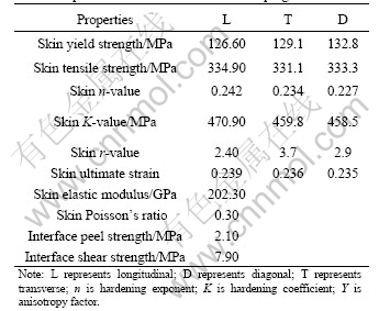
LVDSS consists of three layers, the skin layers are steel with 0.59 mm in thickness respectively and the core layer is polymer material with 0.03 mm in thickness. The material structure is illustrated in Fig.1 and the material properties are given in Table 1. When LVDSS is applied in the structure where the vibration or noise exists, the resin layer sandwiched between two skin layers is capable of effectively conversing the vibrating mechanical energy or the sonic wave into thermal movement of the high-molecular chain inside the core material through the shearing deformation. Energy conversion, from macroscopic point of view, embodies in minimization of the vibration and the reduction of the noise.
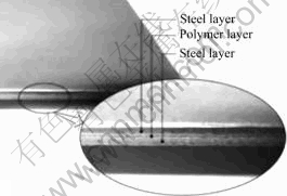
Fig.1 Structure of laminated vibration damping steel sheet
Table 1 Properties of laminated vibration damping steel sheet
3 Interface cohesive model between skin sheets of LVDSS
The interface cohesive model was developed using a contact/interface approach proposed by VINAY et al[13], and the developed model is more suitable for simulation of interface cohesive of LVDSS. Interface delamination process comprises three interrelated phases: the initiation of interface crack, the evolution of the degradation zone, and complete delamination. The core material can be thought as non-linear springs connecting the upper and lower surfaces of the interfacial skins. And these assumed springs contain the tangential and normal strength so that they can resist tangential delamination, normal delamination or mixed delamination. The normal and shear stress on the interface can be calculated by the interface cohesive model. The interface cohesive model describes the evolution of these tractions and the coupling between them as a function of relative normal and tangential strain, and their rate along the interface. The relative normal and tangential strains increase with the relative displacement between skin sheets developing. When the relative strain jump exceeds a critical value, the imaginary springs are assumed to fail, i.e. delamination has taken place. Thereafter, the interaction between the two skin sheets is described solely by the contact friction algorithm. The interface cohesive model defines the evolution of normal and tangential tractions and the coupling between them as a function of the relative normal and tangential strain between skin sheets, respectively. That is, with increasing stretching of the imaginary spring, the spring force attains a maximum value, then decreases, and finally vanishes when the spring ruptures.
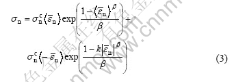
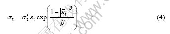
Under isothermal conditions, the stress (��) to resist the stretching of the core material is expressed as follows:
![]()
where ![]() , ��c is the critical strain value, when �� arrives at ��0 the core material strength begins to degrade; ��c is the maximum stress of the core material, which occurs at the critical strain value ��c; �� is rupture factor of the core.
, ��c is the critical strain value, when �� arrives at ��0 the core material strength begins to degrade; ��c is the maximum stress of the core material, which occurs at the critical strain value ��c; �� is rupture factor of the core.
3.1 Delamination modes
Delamination occurs in three different modes[11]. The first mode is pure mode ��, on which delamination occurs in the normal direction; the second mode is pure mode �� and pure mode ��, which is delamination occurs in the two tangential directions, as shown in Fig.2; the third mode is mixed mode, which pure mode �� and pure mode �� both occur in this mode.
3.2 Pure mode of delamination interface cohesive model
Conveniently, the strain components ��i and the traction stress components ��i are normalized by their respective critical strain value ![]() and maximum inter- facial stress
and maximum inter- facial stress ![]() , respectively, as follows:
, respectively, as follows:
![]()
where i=n, t; ��n and ��n are the normal strain and the normal stress of the core material respectively; ��t and ��t are the tangent strain and the tangent stress of the core material respectively. The conditions of pure normal mode are ��n��0, and ��t=0. Under the pure tangent mode, ��t��0, ��n��0. When ��n��0, the contact interface suffers the press stress in normal direction.
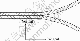
Fig.2 Delamination modes of LVDSS
A resistive compressive normal stress ��n prevents interpenetration of the upper surface and the lower surface when the two surfaces are in contact, and the contact equilibrium heavily depends on the distribution of elastic forces in the contacting region. In this model, it is assumed that the compressive stress does not contribute to any interfacial damage.
The pure normal delamination model takes into consideration the mechanical behavior of the interfacial surface under the interpenetration conditions.
where ![]() is the absolute value of
is the absolute value of ![]() ,k is an interpenetration factor to magnify the repulsive stress ��n. If
,k is an interpenetration factor to magnify the repulsive stress ��n. If ![]() ��0, then
��0, then ![]() and if
and if ![]() ��0, then
��0, then ![]()
In the pure tangent delamination mode, the tangential traction stress (��t) resists the sliding strain ��t. The model is described as follows:
where ![]() is the absolute value of
is the absolute value of ![]()
3.3 Mixed mode of delamination interface cohesive model
In practice, initiation of sliding and delamination usually includes both the pure normal mode and the pure tangent mode. The mixed mode of delamination interface cohesive model is based on the extent of damage[14], is defined by:
![]()
where ![]() and
and ![]() when
when ![]() ��0;
��0; ![]() when
when ![]() ��0; ��n and ��t are the actual normal and tangential strain at the interface;
��0; ��n and ��t are the actual normal and tangential strain at the interface; ![]() and
and ![]() are the critical normal and tangential strain at which the interface fails or delamination takes place in pure normal or pure shear mode, respectively; �� is an effective delamination factor, and only tensile strain (opening) affects delamination. Interface cohesive state is undamaged if �ˣ�1, and delamination will initiate as soon as �� exceeds zero. The tensile and shear state of the interface cohesive state is up to �ˣ�1. After delamination completed, the interface is analyzed solely based on the contact law.
are the critical normal and tangential strain at which the interface fails or delamination takes place in pure normal or pure shear mode, respectively; �� is an effective delamination factor, and only tensile strain (opening) affects delamination. Interface cohesive state is undamaged if �ˣ�1, and delamination will initiate as soon as �� exceeds zero. The tensile and shear state of the interface cohesive state is up to �ˣ�1. After delamination completed, the interface is analyzed solely based on the contact law.
In present paper, �� was used as a decreasing function of the normal and tangent strain. �� is restricted as follows:
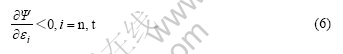
To satisfy the mixed mode criterion in Eqn.(6), the following function is postulated:
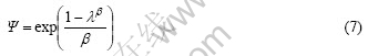
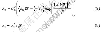
Including the interpenetration term in Eqn.(6), and from Eqn.(7) the final form of the mixed mode cohesive model can be described as follows:
where the operator ![]() is defined as:
is defined as: ![]() if
if ![]() ��0 and
��0 and ![]() =0 if
=0 if ![]() ��0. This mixed model is easily developed for the 3D interfacial surfaces by adding another tangent direction function the same as Eqn.(9).
��0. This mixed model is easily developed for the 3D interfacial surfaces by adding another tangent direction function the same as Eqn.(9).
For an opened fracture interface, there is no contact between the skin layers. Another situation is that delamination has been completed but the skin layers are still in contact. For this closed contact situation, the friction law is applied as follows:
��f=�̦�n (10)
where ��f is maximum friction stress between skin layers, �� is the friction coefficient, ��n is normal stress on contact interface.
3.4 Implementation of interface cohesive model
In this paper, interface cohesive model was implemented in ABAQUS using subroutine VUINTER. User subroutine VUINTER provides a very general interface to define the constitutive behavior across the interface between two surfaces and the subroutine replaces all built-in interfacial constitutive behavior models.
4 Finite element analysis simulation and experiments validation
��T��-peel and lap-shear processes are two important methods to study the interfacial cohesive. In this paper, ��T��-peel and lap-shear processes were researched. The finite element simulations were conducted using ABAQUS EXPLICIT FEA software, and the interface cohesive model described above was implied at interface between skin layers.
4.1 CAE model definition
LVDSS workpiece is 100 mm in length and 25 mm in width for ��T��-peel simulation. Face A and face B move -11 mm and 11 mm along x direction, the end of bottom can only move along y direction, as shown in Fig.3(a). In lap-shear damage simulation, the workpiece length is 12.5 mm and the width is 25 mm. Face C is fastened and face D moves 1 mm along x direction, as shown in Fig.3(b). The skin sheets are modeled with the CPS4R element available in the ABAQUS element library and modeled with four elements along the thickness. The cohesive contact relationship between the skin layers is modeled with interface cohesive model described in above section. Geometrically non-linear deformation of the LVDSS is taken into account in all the simulations.
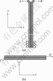
Fig.3 FEA models of simulation: (a) ��T��-peel FEA model; (b) Lap-shear FEA model
4.2 Simulation and experiments
4.2.1 Finite element simulation
The contact normal stress at the interface calculated by the interface cohesive model is shown in Fig.4. As defined in ABAQUS, a positive normal stress denotes a pressure directed into the surface and a negative normal stress denotes a tensile applied on the surface. The contact normal stress on the opened interface of zone A is zero, i.e. there is no cohesive and delamination completed. The contact normal stress at the interface of zone C is more than zero, it means there is normal press stress at the interface. The normal tensile stress occurs in the zone B, in which the delamination occurs. Fig.5 shows the delamination process from initially undamaged adhesive stage to delamination stage in lap- shear damage simulation. From Fig.5(b), we can see that the delamination happens at the two ends of LVDSS where shear stress is zero.
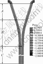
Fig.4 Deformed shape of ��T��-peel simulation
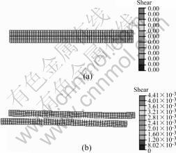
Fig.5 Deformed shape in lap-shear damage simulation: (a) Initial cohesive state; (b) Delamination
4.2.2 Experiments
The ��T��-peel and lap-shear damage experiments were carried out on an Zwick/Roell(Z020) material testing machine. The shape of the ��T��-peel sample is the same as used in ��T��-peel simulation. In the ��T��-peel experiments, the clamping fixtures hold the shoulders of testing sample. Then the fixtures draw the workpiece until the delamination of interface is completed, as shown in Fig.6. Fig.7 shows initial state and final state of he testing samples. In the lap-shear damage experiment, the top and bottom clamping fixtures hold the two ends (A and B) of testing sample respectively. Then the fixtures draw the testing sample until the delamination of interface is completed. Fig.8 shows the shape of testing sample. The width and effective cohesive length(L) of sample are the same as the width and length of workpiece for the lap-shear damage simulation respectively. Fig.9 shows the damaged sample of lap- shear damage experiment.
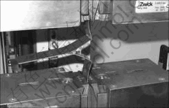
Fig.6 ��T��-peel experiment

Fig.7 ��T��-peel testing samples
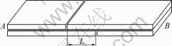
Fig.8 Sample of lap-shear damage experiment
![]()
Fig.9 Lap-shear damaged sample
t4.2.3 Results and discussion
A comparison between the experimentally measured load-displacement curves and those predicted from the simulations of ��T��-peel process is shown in Fig.10.
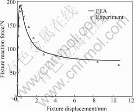
Fig.10 Relationship between fixture reaction force and fixture displacement in ��T��-peel process
When the fixture moves outward about 0.5 mm, the reaction force arrives at the maximum about 190 N. In this stage, the skin sheets begin to bend and the normal tensile stress between the skin sheets increases and the interface crack introduces. The fixture reaction force falls down slowly after maximum reaction force arrived. The interface delamination happens after the tensile stress arrived at the maximum, and the delamination develops along the interface with the fixture drawing. So the fixture reaction force is in relatively smooth state after the fixture moves 4 mm and the reaction force is about 75 N.
Fig.11 illustrates comparison between the experimentally measured load-displacement curves and those predicted from simulations of lap-shear process. Different from Fig.10, the fixture reaction force raises gradually with the relative shear displacement increasing between the skin sheets. When fixture displacement is about 0.52 mm, the fixture reaction force reaches the maximum value 2.5 kN. Also the shear stress between the skins gets the maximum and the shear crack of the core material occurs. Then the core material degrades with the shear strain growing. The contact shear stress and the fixture reaction force reduce. Finally, the fixture reaction force and contact shear stress are reduced down to zero when the fixture displacement gets about 0.75 mm, meaning the interface shear delamination is completed.
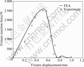
Fig.11 Relationship between fixture reaction force and fixture displacement in lap-shear damage process
In reference to Fig.10 and Fig.11, the numerical calculations capture all the major features of the macroscopic deformation, including the large plastic strains of the adherends, and the agreement of FEA results with experiments results is obtained. So the interface cohesive model can be applied to simulate the cohesive of LVDSS including initiation of interface crack, evolution of the degradation, and complete delamination. The stamp process of LVDSS also can be simulated with this cohesive model.
5 Conclusions
1) An interface cohesive model was developed and implemented in ABAQUS EXPLICIT FEA software using subroutine VUINTER. The model was applied to simulate the ��T��-peel and lap-shear damage process of LVDSS.
2) In ��T��-peel process, the fixture reaction force increases very quickly. Then the force decrease gradually and is near to 75N at last. In lap-shear damage process, different from ��T��-peel process, the fixture reaction force rises gradually. And the force drops to zero gently after peak point reached.
3) Comparing the result of simulation with the experimental results, it is proved that the model is an effective model to simulate the cohesive of LVDSS including initiation of interface crack, evolution of the degradation, and complete delamination.
References
[1] CHEN Y S, HSU T J, CHEN S I. Vibration damping characteristics of laminated steel sheet [J]. Metallurgical Transactions A, 1991, 22A: 653-660.
[2] YOSHIDA M. Press formability of vibration-damping sheet [J]. Journal of JSTP, 1985, 26: 291-230.
[3] KOPP R, ABRATIS C, NUTZMANN M. Lightweight sandwich sheets for automobile applications [J]. Production Engineering Research and Development, 2004, 11: 55-60.
[4] CHENG H S, CAO J, YAO H. Wrinkling behavior of laminated steel sheets [J]. Journal of Materials Processing Technology, 2004, 151: 133-140.
[5] HUANG Y M, LEU D K. Finite-element simulation of the bending process of steel/polymer/steel laminate sheets [J]. Journal of Material Processing Technology, 1993, 52: 319-337.
[6] MAKINOUCHI A, YOSHIDA S, OGAWA H. Finite element simulation of bending process of steel-plastic laminate sheets [J]. Journal of JSTP, 1988, 29: 330-339.
[7] CORONA E, EISENHOUR T. Wiping die bending of laminated steel [J]. International Journal of Mechanical Sciences, 2007, 49: 392-403.
[8] YAO H, CHEN C C, LIU S D. Laminated steel forming modeling techniques and experimental verifications. SAE Paper. No. 2003-01- 0689.
[9] MOHAMMADI S, FOROUZAN S, ASADOLLAHI A. Contact based delamination and fracture analysis of composites [J]. Thin-Walled Structures, 2002, 40: 592-609.
[10] SCHWARTS H, RABINOVITCH O, FROSTIG Y. High-order nonlinear contact effects in cyclic loading of delaminated sandwich panels [J]. Composites: Part B, 2007, 38: 86-101.
[11] JEREMY S, NATHAN W. Plastic dissipation in mixed-mode fatigue crack growth along plastically mismatched interfaces [J]. International Journal of Fatigue, 2006, 28: 1725-1738.
[12] TURON A, CAMANHO P P, COSTA J. A damage model for the simulation of delamination in advanced composites under variable-mode loading [J]. Mechanics of Materials, 2006, 38: 1072-1089.
[13] VINAY K G, ERIC R J, CARLOS G D. Irreversible constitutive law for modeling the delamination process using interfacial surface discontinuities [J]. Composite Structures, 2004, 65: 289-305.
[14] MI Y, CRISFIELD M, DAVIES G. Progressive delamination using interface elements [J]. J Compos Mater, 1998, 32: 1246-1272.
Foundation item: Project(50475020) supported by the National Natural Science Foundation of China
Corresponding author: CHEN Jun; Tel: +86-21-62813424; E-mail: jun_chen@sjtu.edu.cn
Abstract: The material structure of laminated vibration damping steel sheet(LVDSS) was introduced in detail. An interface cohesive model between the skin sheets was developed by using a contact/interface approach, and the model was applied to simulate ��T��-peel and lap-shear processes of LVDSS. The interface contact stress distribution during the ��T��-peel and lap-shear processes is obtained, and the finite element analysis(FEA) results agree satisfactorily with the corresponding experimental results. As a result, the model is suitable to simulate the cohesive of LVDSS
