

Effect of cold rolling on properties and microstructures of
dispersion strengthened copper alloys
GUO Ming-xing(������)1, WANG Ming-pu(������)1, SHEN Kun(�� ��)1,
CAO Ling-fei(�����)2, LEI Ruo-shan(�����)1, LI Shu-mei(����÷)1
1. School of Materials Science and Engineering, Central South University, Changsha 410083, China;
2. School of Engineering, The University of Tokyo, Bunkyo-ku, Tokyo 113-8656, Japan
Received 6 September 2007; accepted 19 November 2007
Abstract:
Mechanical properties and microstructures of unidirectionally and tandem rolled alumina dispersion strengthened copper(ADSC) alloys under different conditions were investigated by tensile test, optical microscopy(OM), transmission electron microscopy(TEM) and scanning electron microscopy(SEM). For unidirectionally rolled ADSC alloys, their strengths and elongations in the longitudinal direction are higher than those in the transverse direction under both cold rolling and annealing conditions. Once fracture appears in their longitudinal stress��strain curves, sudden reduction of overall stress level before complete fracture can be observed in the transverse tensile curves. The anisotropy of mechanical properties for the ADSC alloy can be greatly improved by tandem cold rolling. And no sudden reduction of overall stress level appears in the stress��strain curves for tandem rolled ADSC alloys. The differences of their microstructures and tensile fractures were analyzed. In order to compare the differences of tensile fracture mechanism in different directions, longitudinal and transverse fracture models for unidirectionally rolled ADSC alloys were also introduced.
Key words:
dispersion strengthened copper alloy; unidirectional rolling; tandem rolling; annealing; fracture behavior;
1 Introduction
The pure copper has high electrical and thermal conductivities, but its strength is low both at room and elevated temperatures. Comparably, alumina dispersion strengthened copper(ADSC) alloys possess the excellent high-temperature properties and sufficiently high performance of electrical and thermal conductivities [1-2]. Therefore, the latter has been widely used for contacts, lead wires, electrodes, vacuum technique parts and electrical conductors employed at high temperatures and in nuclear reactors[1,3-4].
ADSC alloys usually are produced by internal oxidation[1,5], which involves diffusion of oxygen in copper alloys and formation of oxide solute. As internal oxidation is a diffusion controlled process, the time required for complete internal oxidation is dependent on the specimen size. Anyway, the internal oxidation time should be as short as possible, which can avoid both the increase of alumina particle size and reduction of particle strengthening effect caused by the longer internal time[6]. Therefore, choosing appropriate internal oxidation procedure parameters is very important for ADSC alloys production. A commercial ADSC alloy Glidcop made by internal oxidation is currently available[1], however, there exists a great shortcoming in the internal oxidation process that ingots can not be heat pressed to complete densification, and other working methods, such as hot extrusion, hot rolling or cold rolling should be used. To well characterize ADSC alloys, much work was focused on their preparation methods and recrystallization behaviors[7-11], while their cold working behaviors were seldom reported, especially their effects on fracture properties and microstructures of the ADSC alloys in different directions. Accordingly, the fracture behaviors and mechanism of ADSC alloys under different conditions were investigated in this work.
2 Experimental
The experimental ADSC alloy (0.05%Al (mass fraction), 0.23%Al2O3 (volume fraction)) was produced by simplified internal oxidation. The fabrication procedure is as follows: Cu-Al(0.05%, mass fraction) alloy induction melting��nitrogen atomization��mixing of Cu-Al alloy and oxidant��internal oxidation at 1 000�� for 1 h��hydrogen reduction at 900 �� for 1 h�� vacuum hot-pressing (950 �� for 3 h, 27 MPa, 1.33��10-2 Pa)��hot-extrusion at 930 ��(extrusion ration 50?1). The sheet specimens of ADSC alloy were cut by electric-spark machining to a thickness of approximate 10 mm. And then several sheets were unidirectionally cold rolled by 80% at room temperature, others were tandem cold rolled by 90% at room temperature. The cold rolled sheets were isothermally annealed at 900 �� for 1 h in the hydrogen furnace. And the definition of longitudinal and transverse directions for the samples is shown in Fig.1.
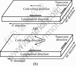
Fig.1 Definition of longitudinal and transverse directions of samples: (a) Unidirectional rolling; (b) Tandem rolling
Lath-shaped tensile specimens were machined from cold rolled and annealed sheets. Uniaxial tensile tests were performed on the INSTRON mechanical test machine, and the tensile speed rate was 2 mm/min.
Grain morphology and other intrinsic microstructural features were revealed using an etchant mixture of 5 mL ferric chloride, 25 mL hydrochloric acid and 100 mL distilled water. The polished and etched metallographic specimens were examined in a NEOPHOT-21 metallographic microscope.
Fracture surfaces of the deformed tensile samples were examined in a KYKY-2800 type scanning electron microscope under controlled voltage of 20 kV.
Transmission electron microscope(TEM) observation of the materials was performed on FEI TECNAIG2 transmission electron microscope at 200 kV. Thin foil samples were electropolished in a twin-jet instrument using an mixture of 30% hydrogen nitrate and alcohol as balance.
3 Results and discussion
3.1 Mechanical properties
Fig.2 shows the difference of the stress��strain curves for unidirectionally rolled ADSC alloys under different conditions. It can be seen that the strengths of cold rolled alloy are much higher than those of annealed alloy in two directions, while the elongations of cold rolled alloy are lower. And both the longitudinal strengths and elongations for cold rolled and annealed alloys are higher than those of transverse direction. The rate of ��long/��trans (��2, ��long is longitudinal strength, ��trans is transverse strength) of annealed ADSC alloy is lower than that of cold rolled (Table1). In addition, from Fig.2, it can also be seen that once fracture appears on the longitudinal stress��strain curves, a sudden reduction of overall stress level can be observed, that is, the ��Twice Fracture�� phenomenon appears. The possible reasons for this phenomenon will be discussed later.
Table 1 Contrast of strength and elongation of ADSC alloys under different conditions
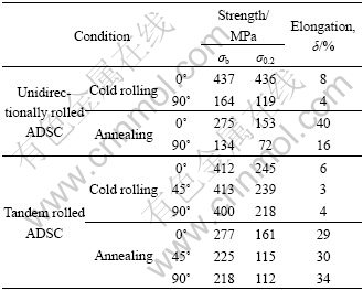
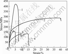
Fig.2 Stress��strain curves of unidirectionally cold rolled ADSC alloys under different conditions: 1 Cold rolling (0?); 2 Annealing (0?); 3 Cold rolling (90?); 4 Annealing (90?)
In contrast, the differences of strengths or elongations of tandem rolled ADSC alloys in three directions (0?, 45? and 90? direct ion) are slight (Fig.3), especially under cold rolling condition, which indicates that mechanical anisotropy of the ADSC alloy can be greatly reduced by tandem rolling. The strengths in three directions all decrease after annealing at 900 ��, but their elongations are improved greatly (Fig.3). The mechanical anisotropy is increased after annealing, and the decrease value of strength in longitudinal direction (0? direction) is the smallest. As higher strength of cold rolled alloys is mainly attributed to the presence of Al2O3 reinforcing phase that acts as barrier to the movement of grain boundaries and dislocations, the concomitant increase in dislocation density is partially responsible for the increased strength of ADSC alloys. And dislocation reacting with each other in the annealing process leads to the decrease of strength. It is well known that the mechanical property is mainly related to its microstructure. Therefore, their different tensile fracture behaviors mentioned above are mainly resulted from the different microstructures.
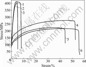
Fig.3 Stress��strain curves of tandem cold rolled ADSC alloys under different conditions: 1 Cold rolling (45?); 2 Cold rolling (90?); 3 Cold rolling (0?); 4 Annealing (0?); 5 Annealing (45?); 6 Annealing (90?)
3.2 Metallographical microstructure
Fig.4 shows metallographical microstructures of unidirectionally rolled ADSC alloys. Highly elongated fibre structure that is parallel to the rolling direction is observed in the cold rolled specimen, and the length-to-width ratio of fibres is much higher (Fig.4(a)). Because the alumina content for this ADSC alloy is lower (about 0.23%, volume fraction), its ability to inhibit the recovery and recrystallization of the Cu-0.23%Al2O3 (volume fraction) alloy is not strong, therefore, a large number of recrystallization grains with different sizes are generated after annealing, yet, the configuration of the elongated fibre structure still exists (Fig.4(b)). The metallographical microstructures of tandem rolled ADSC alloys under different conditions can be observed in Fig.5. It can be seen that, fibre structure does not exist in the matrix of cold rolled ADSC alloy, and its deformation microstructure is much more homogeneous. However, the configuration of cross fibre structure appears after annealing at 900 �� (as arrow directions shown in Fig.5(b)), and recrystallization grains can not be observed by metallographic microscope, which may be resulted from the fact that tandem rolling makes dispersion particles distribute more uniformly, and its ability to inhibit recovery and recrystallization is improved.
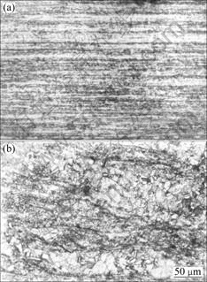
Fig.4 Metallographical microstructures of unidirectionally rolled ADSC alloys under different conditions: (a) Cold rolling by 80%; (b) Annealing at 900 ��
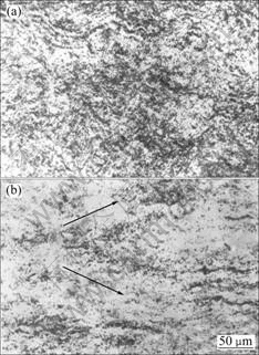
Fig.5 Metallographical microstructures of tandem rolled ADSC alloys under different conditions: (a) Cold rolling by 90%; (b) Annealing at 900 ��
3.3 TEM microstructure
In the cold rolling process, dispersed nano alumina particles can increase the dislocation density and change the deformation substructure as well. These effects depend on both the interparticle spacing and the size of the particles. From Fig.6, the TEM microstructure of unidirectionally rolled ADSC alloys under different conditions can be observed. Elongated dislocation cell substructures with seriously tangled dislocation in them or on their boundary are formed by cold rolling. Yet, its cold rolling microstructure changes obviously after annealing at 900 �� (Fig.6(b)). Larger and longer recrystallization grains are formed, however, many fine alumina particles with tangled dislocations around can be observed in those recrystallization grains. The recrystallization process of particle-containing alloys is determined by many factors[11], including the particle size, the interparticle spacing, and the way of cold rolling, among which the interparticle spacing is the most important. For this ADSC alloy (alumina content is only 0.23%, volume fraction), though the particle size is smaller (about 20-40 nm), the interparticle spacing is longer. The dispersal alumina particles can pin the subgrain boundaries and dislocations, but the pinning effect is not remarkable. Therefore, recrystallization grains with different sizes are formed after annealing at 900 ��.
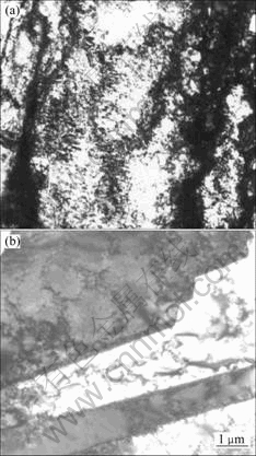
Fig.6 TEM micrographs of unidirectionally rolled ADSC alloys under different conditions: (a) Cold rolling by 80%; (b) Annealing at 900 ��
Fig.7 shows TEM microstructures of tandem rolled ADSC alloys under different conditions. It can be seen that, the TEM microstructure is completely different from that of unidirectionally rolled ADSC alloy. Seriously tangled dislocation lines and dislocation cells can not be observed in the matrix of tandem cold rolled alloy, and many elongated grains cross each other (Fig.7(a)). From Fig.7(b), it can be seen that dislocation cell, whose wall is thinner, is significantly elongated, and its dislocation density is apparently lower than that of unidirectional cold rolling, which indicates that tandem rolling may be favorable to dislocation reaction with each other. After annealing at 900 ��, recrystallization grains appear and also cross each other, indicating that the growth of recrystallization grain has directional characteristic. This may be the main reason that the anisotropy of tandem rolled ADSC alloy after annealing is increased.
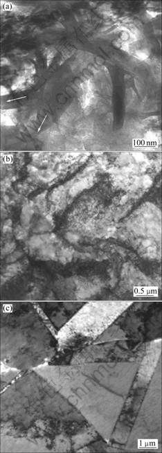
Fig.7 TEM micrographs of tandem rolled ADSC alloys under different conditions: (a, b) Cold rolling by 90%; (c) Annealing at 900 ��
3.4 SEM fracture
In order to explain the differences of stress��strain curves for ADSC alloys under different conditions, especially in different directions, only typical fractures under cold rolling condition were analyzed in this work.
Shallow dimples and cavities with different sizes can be observed on the longitudinal fracture of cold rolled ADSC (Fig.8(a)), which indicates that cold rolled alloy still possesses good ductility. Transverse fractures of the cold rolled alloy are shown in Figs.8(b) and (c). It can be seen that the images of edge and center part are different (Fig.8(b)). Microstructure that is similar to elongated fibre can be observed in the high-magnified image of position A, and no dimple distributes in it (Fig.8(b)).
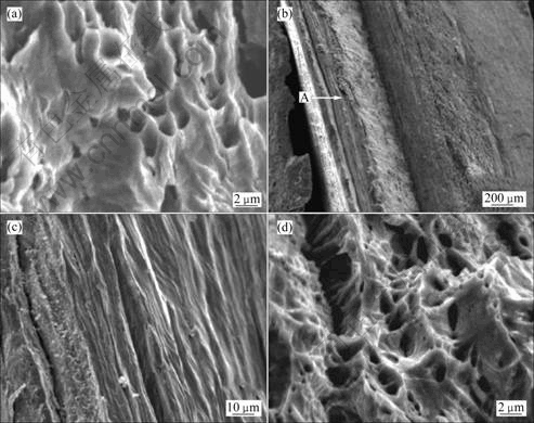
Fig.8 Tensile fracture micrographs of cold rolled ADSC alloy under different conditions: (a) Unidirectionally cold rolling (0? direction); (b) Unidirectionally cold rolling (90? direction); (c) Magnification of position A in Fig.8(b); (d) Tandem cold rolling (0? direction)
By comparing the above stress��strain curves and microstructure, a detailed analysis can be made as follows. It is inevitable to generate larger size alumina particles in copper matrix during the process of internal oxidation. And these alumina particles mainly distribute on fibre or grain boundaries, which causes the bond strength of two adjacent fibres to be lower. As transverse tensile load is vertical to the fibre arrangement direction, its fracture behavior is quite special. Cracks will firstly be produced on the fibre boundary, subsequently, cracks may continually expand along the fibre boundary till to the tip of fibres, just as the fibre is ��split��. If more than one fibre are ��split�� at the same time, transverse tensile loads will suddenly drop in the tension process, and the drop value will be increased with the number of ��split�� fibres. At last, a sudden reduction phenomenon of overall stress level before complete fracture can be observed in the transverse tensile curves, that is, the primary fracture appears (Fig.2). With further tension, the tensile stress will continually increase till to the completely fracture, therefore, the ��Twice Fracture�� phenomenon appears (Fig.2). However, as the longitudinal tensile loads are parallel to the fibre arrangement direction, there are less fibre boundaries that are vertical to the direction of tensile loads. A sudden reduction of overall stress level will not appear, therefore, the ��Twice Fracture�� phenomenon can not be observed in the longitudinal tensile curves.
As tensile fractures of tandem cold rolled alloys in the three directions are similar, which explains the reason that the mechanical anisotropy of ADSC alloy can be reduced by tandem rolling. Only one fracture is shown in Fig.8(d), which is similar to the longitudinal tensile fracture of unidirectionally cold rolled ADSC alloy.
3.5 Tensile fracture model
In order to analyze tensile fracture behaviors of Cu-0.23%Al2O3 (volume fraction) alloy under different conditions, two models for the longitudinal and transverse tensile fracture process are shown in Fig.9. In Fig.9, the black round spots represent alumina particles, the elongated band structure represents fibre structure formed in the cold rolling process, r is particle radius, d and h are the interparticle spacing in longitudinal and transverse directions respectively. As mentioned above, the longitudinal tensile loads are parallel to the aligned direction of fibre boundary, so it is not easy to form cracks on the fibre boundary. But due to large differences of properties between alumina particles and copper matrix, cracks will be firstly formed at the matrix/particle interface as alumina particles decohere from the matrix (Fig.9A(b)). Then the cracks grow and coalesce into voids in the loading direction (Fig.9A(c)). Finally, voids coalesce in rows and complete fracture occurs (Fig.9A(d)). It can be seen that the process of longitudinal tensile fracture of ADSC alloys has much in common with that of ordinary metal-based composites containing dispersion strengthened phases[12-14]. This model can also be used to explain the fracture processes of the tandem rolled ADSC alloys in three directions. Because tandem rolled ADSC alloys do not have fibre structure, and the effect of fibre boundary on tensile fracture behaviors can be ignored, the elongated band structure in the models should be removed.
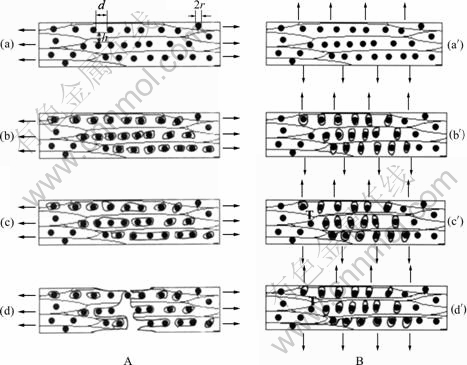
Fig.9 Tensile fracture models of unidirectionally cold rolled ADSC alloys: (A) Longitudinal direction; (B) Transverse direction
Similarly, the whole transverse tensile fracture mechanism can be seen in Fig.9B, which is completely different from the longitudinal one. At first, cracks are formed at the matrix/particle interface (Fig.9B(b��)). As the tensile load is vertical to the aligned direction of fibre boundary, cracks are easily formed on the fibre boundary (Fig.9B(c��)). These cracks will quickly expand to the tip of fibres with further tension (Fig.9B(d��)); however, those cracks formed at the matrix-particle interface are difficult to grow and coalesce. When the amount of cracks on the fibre boundary is increased to a certain degree, a sudden reduction phenomenon of overall stress level appears on the transverse tensile curves. But those cracks on the fibre boundary are still not connected with each other, unless the cracks distributing around the dispersion alumina particles can grow and coalesce. Therefore, after the primary fracture, with further tension, the stress recoveries to a certain value, till to complete fracture. At last, the ��Twice Fracture�� phenomenon can be seen on the transverse tensile curves.
4 Conclusions
1) For unidirectionally cold rolled ADSC alloys, the mechanical anisotropy between the longitudinal and transverse directions is more serious, and their tensile fracture behaviors are also particular, especially in transverse direction.
2) An appropriate tandem rolling technology used in this work can greatly reduce the anisotropy of mechanical properties. And the microstructures of tandem rolled ADSC alloys are quite different from those of unidirectionally rolled alloys even under the same condition.
References
[1] NADKARNI A V. Dispersion strengthened copper properties and applications [J]. Metallurgical Soc of AIME, 1984: 77-101.
[2] SYNK J E, VENDULA K. Structure and mechanical behaviour of powder processed dispersion strengthened copper [J]. Mater Sci Technol, 1987, 3: 72-75.
[3] LEE J, KIM Y C, LEE S H, AHN S H, KIM N J. Correlation of the microstructure and mechanical properties of oxide-dispersion- strengthened coppers fabricated by internal oxidation[J]. Metallurgical and Materials Transaction A, 2004, 35A: 493-502.
[4] SATO S, HATANO T, KURODA T, FUROYA K, HARA S, ENOEDA M, TAKATSU H. Optimization of HIP bonding conditions for ITER shielding blanket/first wall made from austenitic stainless steel and dispersion strengthened copper alloy [J]. J Nucl Mater, 1998, 263: 265-270.
[5] TAKAHASHI T, HASHIMOTO Y, KOYAMA K. Effects of Al concentration and internal oxidation temperature on the microstructure of dilute Cu-Al alloys after internal oxidation [J]. Journal of the Japan Institute of Metals, 1989, 53(8): 814-820.
[6] MORRIS D G, MORRIS M A. Rapid solidification and mechanical alloying techniques applied to Cu-Cr alloys [J]. Materials Science and Engineering A, 1988, A104: 201-213.
[7] SHI Zi-yuan, YAN Mao-fang. Preparation of Al2O3-Cu composite by internal oxidation [J]. Journal of Engineering and Applied Science, 1998, 34: 103-106.
[8] BAKER I, LIU L. Effect of internal oxidation on the stored energy and recrystallization of copper single crystals [J]. Scripta Metallurgica et Materialia, 1994, 30(9): 1167-1170.
[9] CHENG Jian-yi, WANG Ming-pu, LI Zhou, WANG Yan-hui, XIAO Cong-wen, HONG Bin. Fabrication and properties of low oxygen grade A12O3 dispersion strengthened copper alloy [J]. Trans Nonferrous Met Soc China, 2004, 14(1): 121-126.
[10] KIM S H, LEE D N. Annealing behavior of alumina dispersion-strengthened copper strips rolled under different conditions [J]. Metallurgical and Materials Transaction A, 2002, 33(6): 1605-1616.
[11] MANDAL D, BAKER I. On the effect of fine second-phase particles on primary recrystallization as a function of strain [J]. Acta Mater, 1997, 45(2): 453-461.
[12] SRIVATSAN T S, AL-HAJRI M, SMITH C, PETRAROLI M. The tensile response and fracture behavior of 2009 aluminum alloy metal matrix composite [J]. Materials Science and Engineering A, 2003, A346: 91-100.
[13] SRIVATSAN T S, TROXELL J D. Tensile deformation and fracture behavior of a ductile phase reinforced dispersion strengthened copper composite [J]. Journal of Materials Science, 1999, 34: 4859-4866.
[14] SRIVATSAN T S, DHANA SINGH K, TROXELL J D. Tensile behavior of an oxide dispersion strengthened copper-niobium composite [J]. Materials Letters, 1996, 28: 423-429.
Foundation item: Projects(2002AA302505, 2006AA03Z517) supported by the National High-Tech Research and Development Program of China
Corresponding author: GUO Ming-xing; Tel: +86-731-8830264; Fax: +86-731-8876692; E-mail: mingxingguo@163.com
