
���������Ը�������ṹ���ע����ͳ�����ȵ�Ӱ��
�����ף������������֣�������
(���ϴ�ѧ ���繤��ѧԺ������ ��ɳ��410083)
ժ Ҫ��
ժ Ҫ�����û���Navier-Stokes�˶����̿�����Moldflow MPI 6.0�������Ծۼ���ϩ����� (PMMA)����Ϊ����, ����ǻѹ��Ϊ100 MPa�������¶�Ϊ250 �桢��ͬģ���¶��£��о������������(�ṹ����λ�á��ṹ��״���ṹ����ߴ硢�ṹ����Ⱥ��ṹ��ǻ����ߴ�)���ṹ������ȵ�Ӱ�졣�о�����������ṹ����ǻĩ�˼��ԽС������Խ������ṹ����ǻĩ�˼�೬��ijһֵʱ���ṹ�����������λ���أ��ṹ���ԽС������Խ��ṹ����ߴ�Խ����ʱ������������ԽС������Խ���ǻ����ߴ����ṹ�ߴ����ԽС��Խ�������ṹ����ṹ�����������������ء�
�ؼ��ʣ�
�ṹ�������������������������������
��ͼ����ţ�TG249.9 ���ױ�ʶ�룺A ���±�ţ�1672-7207(2008)05-1000-05
Influence of part��s geometry characters on filling length of injection molded parts with high aspect ratio micro structures
JIANG Bing-yan, CHU Chun-peng, TANG Mei-lin, SHEN Long-jiang
(School of Mechanical and Electrical Engineering, Central South University, Changsha 410083, China)
Abstract: With Moldflow MPI 6.0 software based on Navier-Stokes momentum equation for PMMA material, the influences of geometry characters of a part, such as micro structures�� position, shape, section dimension, aspect ratio and cavity�� width, on the filling length of micro structures were investigated under the cavity pressure 100 MPa, and at melt temperature 250 �� with different mold temperatures. The results show that the distance between microstructure and cavity terminal is smaller, the filling is longer, but when the distance surpasses one value, the filling length has nothing to do with the position of the microstructure. The smaller the microstructure inclination angle, the longer the filling. The bigger the size of microstructure section, the smaller the resistance of the melts in filling, and the longer the filling. The difference between the size of the cavity section and the size of the microstructure is less, the filling is more advantageous, but the filling length of microstructure has nothing to do with the high aspect ratio.
Key words: parts with micro structures; filling length; high aspect ratio; geometry character
����/����ѧ�����IJ��Ϸ�չ���Ը�������ṹ���������Խ��Խ��[1-2]��ע����ͼ�����������������Ч���ͺġ����ܳ����ṹ�������Ѽ���֮һ��Ȼ���������ṹ�����ǻԶԶС�ڳ�����ǻ��������������������Ѷȣ�ͬʱ��Ҳ�����������ȴ�ٶȣ���ˣ���������ṹ������ͼ�������[3-7]���ṹ����������ṹ����Ĺؼ�����֮һ��YU��[8-9]�Ծ۱�ϩ(PP)�;ۼ���ϩ�����(PMMA)����Ϊ���������Ϊ5���ṹ����Ϊ50 ��m��100 ��m�Ľϳ��ͽ϶�2�־���ģ�ͽ���ע����ͷ��棬�����ṹ�ij��������ע���ٶȡ�ģ���¶ȡ��������������Լ��ṹ��λ���йأ���ģ���¶�Ӱ�����Young[10]���о�����������ṹ�ij��������ģ���¶Ⱥ�ע���ٶ��йأ������ṹԽ���������Խ�Shen��[11-12]�Գ���Ϊ�����о���ע��ʱ�䡢ģ���¶ȡ�ע���¶��Լ�ע��ѹ���ȳ��Ͳ������ṹ�����Ӱ�죬��Ϊģ���¶���Ӱ�����ij����ղ���[13-15]��Ŀǰ���ṹע����͵ij����ղ�����ѧ�����о����ص㣬���ǣ����ǶԼ����������ṹ������ȵ�Ӱ���о����١��ڴˣ����������о��ṹλ�á���״������ߴ硢������Լ���ǻ�Ľ���ߴ���ṹ������ȵ�Ӱ�졣
1 ����ʵ�鷽��
1.1 ����ģ��
�ṹע����ͼ���ע����������һ��dz���Ҫ�����������ָ�����������mgΪ������λ������ߴ����1 mm�����Ǿ������Ľṹ�ȣ��絼��塢DVD/CD�������������оƬ�ȡ�������һ���壬������ṹע����ͼ�2D����ģ�ͣ���ͼ1��ʾ�����У�![]() Ϊ�ṹ���������ڱ�ƽ�о��룻
Ϊ�ṹ���������ڱ�ƽ�о��룻![]() Ϊ��ǻ�߶ȣ�
Ϊ��ǻ�߶ȣ�![]() Ϊ�ṹ�߶ȣ�
Ϊ�ṹ�߶ȣ�![]() Ϊ�ṹ���ȣ�
Ϊ�ṹ���ȣ�![]() Ϊ��ǻ���ȣ�Ϊ8 mm��
Ϊ��ǻ���ȣ�Ϊ8 mm��![]() /
/![]() Ϊ�ṹ����ȣ���Ϊ�ṹ��ǡ�ͼ1(c)��ʾΪ���ṹ����ģ�ͣ����ṹ����Ϊ0.1 mm��ģ��Ϊ2 mm����Ϊ1 mm�����ṹλ�ô���������ΪA��B��C��D��E��F��
Ϊ�ṹ����ȣ���Ϊ�ṹ��ǡ�ͼ1(c)��ʾΪ���ṹ����ģ�ͣ����ṹ����Ϊ0.1 mm��ģ��Ϊ2 mm����Ϊ1 mm�����ṹλ�ô���������ΪA��B��C��D��E��F��
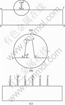
(a) ���ṹ����ģ�ͣ�(b) �ṹ�Ŵ�ͼ��(c) ���ṹ����ģ��
ͼ1 �ṹע����ͼ�2D����ģ��
Fig.1 2D physical model of injection molded parts with micro structures
1.2 ģ�ͽ���������
����Pro/ENGINEER Wildfire2.0 �����ṹ���ģ�͡�������������ֱ��Ӱ�������ֵ�����������ľ�ȷ�ԣ�����̫������������ᵼ�¼�����ֹ�����ԣ���������HYPERMESH�н���ǰ������Lee[16]���о������������ƽ�������ܴ����Ǿ��ȼ������������䲻���������ܶ����ܴ��ģ�ͣ���ˣ����ṹע����ͼ�����3D������л��֡�Ϊ�˻���ṹ������ȵ�ȷֵ�����ټ���������ٶȣ����ṹ���丽��������ýϸߵ������ܶȣ�Ȼ����MoldFlow�������ٴ�����3D�����ṹ��������ͼ2��ʾ���������ν��ڣ�ֱ������ģ����ߣ�ʹ�������ǻ�������������
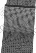
ͼ2 �ṹ������
Fig.2 Gridding on micro structure
1.3 �������
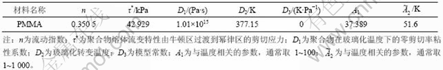
���ϲ���LG Chemical��˾�ͺ�ΪIG-840�ľۼ���ϩ���֬( PMMA)�������ܲ������1��ʾ��
��1 ����PMMA���ܲ���
Table 1 Characteristic parameters of PMMA
2 �����������
����ʵ���н���ǻѹ����Ϊ100 MPa�������¶�Ϊ250 �棬�ڲ�ͬģ���¶��£�����MoldFlow MPI 6.0��Flow����ģ��Ը��ֲ�ͬ����ģ�ͽ��г�����棬���о��ṹ����λ�á��ṹ����ߴ硢�ṹ��״���ṹ������Լ���ǻ����ߴ���ṹ������ȵ�Ӱ�졣
2.1 �ṹλ�öԳ�����ȵ�Ӱ��
ͼ1(c)��ʾ�Ķ��ṹע����ͼ�ģ�ͣ��ṹA��B��C��D��E��F����ǻĩ�˵ľ������μ�С��Ϊʹ����Ч���������ԣ���ģ���¶�tw=25 ��ʱ���з���������ṹ���뽽�ڽϽ�ʱ���������Ƚϵͣ����ž���������ṹ�ij������������������ڶ�ֵ����ͼ3��ʾ�������ϵ����ṹ����ڴ�ʱ����Ϊ��ǻ��δ������δ�γ��㹻��ѹ������ˣ�����ڴ��������ᣬ���ϲ������룻����ǻ�����ﵽ��ѹ�����ϻ����γ��ƶ���ʱ��϶̵��ṹ��ڣ����ṹ���г����ˣ��뽽��ԽԶ���ṹ�������Խ��
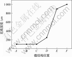
ͼ3 �ṹλ�ö��������ȵ�Ӱ��
Fig.3 Influence of micro structures�� position on its filling length
2.2 �ṹ��״�Գ�����ȵ�Ӱ��
ͼ1(b)�Цȱ�ʾ�ṹ��ǽǶȡ���![]() ���Ȳ��䣬��Dz�ͬʱ���ṹ��״Ҳ��ͬ��Ϊ���о��ṹ������״���������ȵ�Ӱ�죬��ģ���¶ȷֱ�Ϊ90 ���95 ��ʱ���Բ�ͬ��ǵ��ṹ���з�������������ṹ��ǽǶȵļ�С���ṹ�ij�����������ӣ���ͼ4��ʾ���ṹ��ǽǶ�ԽС���������ǻ�����ṹʱ����Ǹı��ԽС���ʵ��ṹ��ͬʱ�������ٶ�Խ���ṹ����Խ�
���Ȳ��䣬��Dz�ͬʱ���ṹ��״Ҳ��ͬ��Ϊ���о��ṹ������״���������ȵ�Ӱ�죬��ģ���¶ȷֱ�Ϊ90 ���95 ��ʱ���Բ�ͬ��ǵ��ṹ���з�������������ṹ��ǽǶȵļ�С���ṹ�ij�����������ӣ���ͼ4��ʾ���ṹ��ǽǶ�ԽС���������ǻ�����ṹʱ����Ǹı��ԽС���ʵ��ṹ��ͬʱ�������ٶ�Խ���ṹ����Խ�

1��90 ��; 2��95 ��
ͼ4 �ṹ��״���������ȵ�Ӱ��
Fig.4 Influence of micro structures�� shape on its filling length
2.3 �ṹ����ߴ�Գ�����ȵ�Ӱ��
��ͼ1(a)��ʾ��![]() =
=![]() ���ı䳤��
���ı䳤��![]() ��������Ⱦ�Ϊ10���ֱ���ģ���¶�Ϊ90 ���95 ��ʱ���г�����棬�����ͼ5��ʾ���ɼ��������ṹ����ߴ�����ӣ����������������ṹ����ߴ� Խ���������ǻ�����ṹʱ�ܵ�����������ԽС���ṹԽ���׳���ṹ����ߴ�Խ��������ģ�ڵ���ԽӴ����ԽС���������ȴʱ��Ҳ��Խ�����Ӷ��������������ṹ���������ȡ�
��������Ⱦ�Ϊ10���ֱ���ģ���¶�Ϊ90 ���95 ��ʱ���г�����棬�����ͼ5��ʾ���ɼ��������ṹ����ߴ�����ӣ����������������ṹ����ߴ� Խ���������ǻ�����ṹʱ�ܵ�����������ԽС���ṹԽ���׳���ṹ����ߴ�Խ��������ģ�ڵ���ԽӴ����ԽС���������ȴʱ��Ҳ��Խ�����Ӷ��������������ṹ���������ȡ�
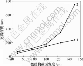
1��90 ��; 2��95 ��
ͼ5 �ṹ����ߴ���������ȵ�Ӱ��
Fig.5 Influence of micro structures�� section dimension on its filling length
2.4 �ṹ����ȶԳ�����ȵ�Ӱ��
��ͼ1(a)��ʾ�����Ⱦ�Ϊ100 ��m���ı��ṹ������ȣ���ģ���¶ȷֱ�Ϊ90 ���95 ��ʱ���г�����档�ɼ�����ģ���¶�tw=90 ��ʱ�������С��10���ṹ�������������������ȵ������ṹ���������С�����ı�������tw= 95 ��ʱ�������ṹ������ȼ���һ�£���ͼ6��ʾ���ɼ����ṹ���������ֻ��ӿ������ǻ�������ȴ�ٶȣ��Ӷ�Ӱ���ṹ�ij�����ǣ�����ģ���¶ȵ����ӣ�����Ӱ��ͻ���С��������ʧ��
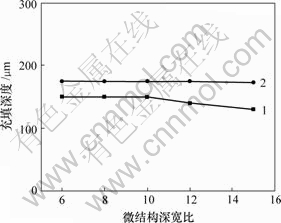
1��90 ��; 2��95 ��
ͼ6 �ṹ����ȶ��������ȵ�Ӱ��
Fig.6 Influence of micro structures�� aspect ratio on its filling length
2.5 ��ǻ����ߴ�Գ�����ȵ�Ӱ��
��ͼ1(a)��ʾ��afgh��ʾ��ǻ���棬�ֱ�ı���ǻ���Ⱥ���ǻ�߶ȣ���ģ���¶ȷֱ�Ϊ90 ���95 ��ʱ��������з�������������ͼ7���ɼ���������ǻ����ߴ�ļ�С���ṹ�ij���������������������ṹ��������ǻ�������ԽС�����������ṹʱ���ܵ�����ԽС���������Ҳ��Խ�
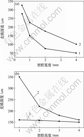
1��90 ��; 2��95 ��
(a) ��ǻ���ȣ�(b) ��ǻ�߶�
ͼ7 ��ǻ����ߴ���ṹ������ȵ�Ӱ��
Fig.7 Influence of cavity�� section dimension on micro structures�� filling length
3 �� ��
a. �ṹ�����������λ���йأ��ṹ����ǻĩ�˼��ԽС������Խ��ҳ������������ǻĩ�˼��ʷ����Եݼ��������ṹ����ǻĩ�˼�೬��ijһֵʱ���ṹ�����������λ���ء�
b. �ṹ�������������״�йأ��ṹ���ԽС������Խ�
c. �ṹ��������������ߴ��йأ��ṹ����ߴ�Խ����ʱ������������ԽС������Խ�
d. �ṹ�����������������أ�������ߴ���ͬ��������Ȳ�ͬ���ṹ����ͬ�����£��������ȼ�����ͬ��
e. �ṹ�����������ǻ����ߴ��йأ���ǻ����ߴ����ṹ�ߴ����ԽС��Խ�������ṹ���
�ο����ף�
[1] R?tting O, R?pke W, Becker H, et al. Polymer microfabrication technologies[J]. Microsystem Technologies, 2002, 8(1): 32-36.
[2] Studer V, P��pin A, Chen Y. Nanoembossing of thermoplastic polymers for microfluidic applications[J]. Applied Physics Letters, 2002, 80(19): 3614-3616.
[3] Yao D. Rapid thermal response injection molding for microfabrication[D]. Amherst: The University of Massachusetts, 2001.
[4] Harris C, Despa M S, Kelly K W. Design and fabrication of a cross flow micro heat exchanger[J]. Microelectromechanical Systems, 2002, 9(4): 502-508.
[5] Ǯ����, ����. ���嶯��ѧ�о���չ����״[J]. ���վ������켼��, 2005, 41(6): 11-14.
QIAN Xiao-rong, SHEN Hong-ji. Development on hydrokinetic of microfluidic flow[J]. Aviation Precision Manufacturing Technology, 2005, 41(6): 11-14.
[6] Kari M, Joni H, Pertti P, et al. Replication of submicron features using amorphous thermoplastics[J]. Polymer Engineering and Science, 2002, 42(7): 1600-1608.
[7] ������, �� ��, ����, ��. ���ǽᾧDZ�ȵ�LDPE�ṹ��ע�����ģ���¶ȳ�[J]. ���ϴ�ѧѧ��: ��Ȼ��ѧ��, 2006, 37(3): 532-536.
JIANG Bing-yan, WENG Can, LUO Jian-hua, et al. Cavity temperature of LDPE injection molded parts with microstructure region considering latent heat[J]. Journal of Central South University: Science and Technology, 2006, 37(3): 532-536.
[8] XU Guo-jun, YU Li-yong, Lee L J, et al. Experimental and Numerical studies of injection molding with microfeatures[J]. Polymer Engineering and Science, 2005, 45(6): 866-875.
[9] YU Li-yong, Chee G K, Lee L J. Experimental investigation and numerical simulation of injection molding with micro-features[J]. Polymer Engineering and Science, 2002, 42(5): 871-888.
[10] Young W B. Simulation of the filling process in molding components with micro channels[J]. Microsystem Technologies, 2005, 2: 410-415.
[11] Shen Y K, Wu W Y. An analysis of the three dimensional micro injection molding[J]. International Communications in Heat and Mass Transfer, 2002, 29(3): 423-431.
[12] Shen Y K, Yeh S L, Chen S H. Three dimensional non Newtonian computations of micro injection molding with the finite element method[J]. International Communications in Heat and Mass Transfer, 2002, 29(5): 643-652.
[13] Sha B, Dimov S S, Pham D T, et al. Study of factors affecting aspect ratios achievable in micro-injection molding[C]// Proceedings of First International Conference on Multi-Material Micro Manufacture. Kurstruhe, Germany, 2005: 107-110.
[14] Despa M S, Kelly K W, Collier J R. Injection molding using high aspect ratio micro structures mold inserts produced by L IGA techniques [C]//Proceedings of SPIE ��The International Society for Optical Engineering. Bellingham: SPIE, 1998: 286-294.
[15] Michaeli W, Spennemann A. A new injection molding technology for micro parts[J]. Journal of Polymer Engineering, 2001, 21(23): 87-98.
[16] Lee J L. Modeling and simulation in polymer micro-injection molding[C]//��һ��߾�����μӹ����������Ԥ�����ѧ�����ֻ����ļ�. ����: ��ѧ��ҵ������, 2006: 15-30.
Lee J L. Modeling and simulation in polymer micro-injection molding[C]//Proceeding of the 1st International Congress on Modeling, and Simulation in Polymer Engineering and Science. Beijing: Chemical Industry Press, 2006: 15-30.
�ո����ڣ�2007-12-08�������ڣ�2008-03-06
������Ŀ��������Ȼ��ѧ����������Ŀ(50475140)
ͨ�����ߣ�������(1963-)���У��㽭�ֽ��ˣ����ڣ�����ע��������ۺ�Ӧ���о����绰��0731-8836035��E-mail: jby@mail.csu.edu.cn
