
J. Cent. South Univ. Technol. (2010) 17: 1357-1363
DOI: 10.1007/s11771-010-0642-x![]()
3D FEM analysis for layered rock considering anisotropy of shear strength
ZHANG Yu-jun(�����), ZHANG Wei-qing(����)
Institute of Rock and Soil Mechanics, Chinese Academy of Sciences, Wuhan 430071, China
? Central South University Press and Springer-Verlag Berlin Heidelberg 2010
Abstract:
An empirical expression of cohesion (C) and friction angle ![]() for layered rock was suggested. This expression was compared with a test result made by the former researchers. The constitutive relationship of a transversely isotropic medium and Mohr-Coulomb criterion in which C and
for layered rock was suggested. This expression was compared with a test result made by the former researchers. The constitutive relationship of a transversely isotropic medium and Mohr-Coulomb criterion in which C and ![]() vary with directions were employed, and a relative 3D elasto-plastic FEM code was developed, in which the important thing was to adopt a search-trial method to find the orientation angle (��) of shear failure plane (or weakest shear plane) with respect to the major principal stress as well as the corresponding C and
vary with directions were employed, and a relative 3D elasto-plastic FEM code was developed, in which the important thing was to adopt a search-trial method to find the orientation angle (��) of shear failure plane (or weakest shear plane) with respect to the major principal stress as well as the corresponding C and ![]() Taking an underground opening as the calculation object, the numerical analyses were carried out by using the FEM code for two cases of transversely isotropic rock and isotropic rock, respectively, and the computation results were compared. The results show that when the rock is a transversely isotropic one, the distributions of displacements, plastic zones and stress contours in the surrounding rock will be non-axisymmetric along the tunnel��s vertical axis, which is very different from that of isotropic rock. The stability of the tunnel in transversely isotropic rock is relatively low.
Taking an underground opening as the calculation object, the numerical analyses were carried out by using the FEM code for two cases of transversely isotropic rock and isotropic rock, respectively, and the computation results were compared. The results show that when the rock is a transversely isotropic one, the distributions of displacements, plastic zones and stress contours in the surrounding rock will be non-axisymmetric along the tunnel��s vertical axis, which is very different from that of isotropic rock. The stability of the tunnel in transversely isotropic rock is relatively low.
Key words:
1 Introduction
It is well-known that a layered rock possesses obvious anisotropic behavior of deformation and strength, compared with a homogeneous rock, its conditions of stability and failure are more complicated [1]. At present a layered rock can be treated theoretically as a transversely isotropic medium, its stress-strain relationship includes five constants, and the strength parameters also exhibit some spatial distribution modes. In the past many years the scholars at home and abroad have done constantly researches on anisotropic shear strength of layered rock masses. For instance, LEE and PIETRUSZCZAK [2] assumed that the crack initiation of transversely isotropic rock masses is governed by the Hoek-Brown failure criterion, and described the anisotropy of the strength through the orientation dependence of strength parameters m and s. SAROGLOU and TSIAMBAOS [3] modified the Hoek-Brown failure criterion by incorporating a new parameter (kb) to account for the effect of strength anisotropy. XU and ZHANG [4] obtained the orthotropic equivalent shear strength parameters for fractured rock mass by applying the simulation method of joint network, damage mechanics and theory of joint tensor. YANG et al [5] established an implicit anisotropic yield criterion for jointed rock masses through the Mohr-Coulomb failure condition for plane in every direction. YU [6] set up a strength criterion that can describe the inherent anisotropy as well as two failure modes of cracking and yielding for geotechnical material. COLAK and UNLU [7] undertook a study to determine the effect of transverse anisotropy of sedimentary rocks on the Hoek-Brown strength parameter (mi). LYDZBA et al [8] considered a laminate consisting of interchanging layers of sandstone and claystone to be a particular formation and dealt with the specification of transversely isotropic failure criterion for stratified rocks. PIETRUSZCZAK et al [9] described the inherent anisotropy of sedimentary rocks by employing a second-order microstructure tensor, in which the distribution function specified the directional dependence of strength parameters. USHAKSARAEI and PIETRUSZCZAK [10] presented a macroscopic transversely isotropic failure criterion for structural masonry based on the critical plane approach. PIETRUSZCZAK and MROZ [11] formulated the failure criteria for the cohesive-frictional materials using two different approaches.
The above-mentioned scholars inspected and verified the anisotropic failure criteria suggested by themselves using laboratory tests and/or computation analyses, but they did not apply the criteria to FEM and other numerical simulations with practical background of geotechnical engineering.
There should be ��=C(��)+��tan ��(��) if Mohr-Coulomb criterion is employed to describe the failure characteristics of a layered rock. That is, both cohesion (C) and internal friction angle![]() are not constants, but are functions of the angle between the failure surface and the foliated plane (��) (or the direction of maximum principal stress ��1) [12-13]. For this reason, an empirical expression of C and
are not constants, but are functions of the angle between the failure surface and the foliated plane (��) (or the direction of maximum principal stress ��1) [12-13]. For this reason, an empirical expression of C and ![]() for a layered rock was suggested. On the basis of this constitutive relationship of a transversely isotropic medium and Mohr-Coulomb criterion in which C and
for a layered rock was suggested. On the basis of this constitutive relationship of a transversely isotropic medium and Mohr-Coulomb criterion in which C and ![]() vary with directions were introduced. Therefore a relative 3D elasto-plastic FEM code was developed. Taking an underground opening as the calculation object, the numerical analyses were carried out for both cases of a transversely isotropic rock and an isotropic rock, respectively.
vary with directions were introduced. Therefore a relative 3D elasto-plastic FEM code was developed. Taking an underground opening as the calculation object, the numerical analyses were carried out for both cases of a transversely isotropic rock and an isotropic rock, respectively.
2 Anisotropic shear strength of layered rock
2.1 Expression of C and ![]() for layered rock
for layered rock
Generally speaking, the shear strength of a layered rock (S) has a minimum value of Smin and a maximum value of Smax in directions parallel to and perpendicular to the foliated plane, respectively, and among them S varies with angle �� with respect to the foliated plane according to some rules (Fig.1) as:
S=f(Smin, Smax, ��) (1)
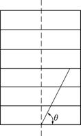
Fig.1 Inclination of plane with C and![]() concerned �� with respect to foliated plane
concerned �� with respect to foliated plane
JAEGER [14] also gave an expression of S:
S=S1+S2cos[2(��-��)] (2)
where S1 and S2 are constants; �� and �� are angles between the failure surface as well as the foliated plane and the direction of maximum principal stress ��1, respectively (see Fig.2).
As a kind of approximation, an empirical expression for C and ![]() in any direction with �� was suggested [15]:
in any direction with �� was suggested [15]:
 (3)
(3)
where 0�ܦȡܦ�/2; Cmin, ![]() Cmax and
Cmax and ![]() are the cohesion and the internal friction angles parallel to and perpendicular to the foliated plane, separately.
are the cohesion and the internal friction angles parallel to and perpendicular to the foliated plane, separately.
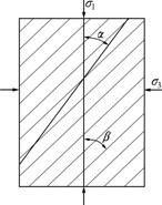
Fig.2 Inclination �� and �� of failure plane and foliate plane with respect to ��1
2.2 Comparison with earlier test result
Here, the test results made by ATTEWELL and SANDFORD [16] were used. For Penrhyn slate through changing �� of the foliated plane with respect to the axis of maximum principal stress, ATTEWELL and SANDFORD [16] obtained C and ![]() values for different �� magnitudes under the condition of triaxial compression. A curve-fit formula of C and
values for different �� magnitudes under the condition of triaxial compression. A curve-fit formula of C and ![]() acquired by ATTEWELL and SANDFORD [16] is expressed as
acquired by ATTEWELL and SANDFORD [16] is expressed as
![]() (4)
(4)
where C1, C2, ![]() and
and ![]() are constants; �� and �� are inclinations of the failure surface and the foliated plane with respect to ��1.
are constants; �� and �� are inclinations of the failure surface and the foliated plane with respect to ��1.
ATTEWELL and SANDFORD [16] did not give the concrete values of C1, C2, ��,![]() and ��. In this work, a curve-fitting was made on the basis of results in Ref.[16] (directional influence curves of cleavage anisotropy upon C (Pa) and
and ��. In this work, a curve-fitting was made on the basis of results in Ref.[16] (directional influence curves of cleavage anisotropy upon C (Pa) and ![]() (?) at failure of the rock specimens) and produce:
(?) at failure of the rock specimens) and produce:
![]() (5)
(5)
From Eq.(5) we have

Thus
 (6)
(6)
Let ��=90?, that is, the foliated plane is perpendicular to the axis of ��1 and the change of ��, �� and �� in Eqs.(4), (6) from 0? to 90?, the relative curves for C and ![]() are demonstrated in Fig.3. From Fig.3 it can be seen that Eqs.(4) and (6) have a good agreement.
are demonstrated in Fig.3. From Fig.3 it can be seen that Eqs.(4) and (6) have a good agreement.
3 Formulae of 3D FEM
3.1 Constitutive relationship
For the transversely isotropic rock shown in Fig.4,
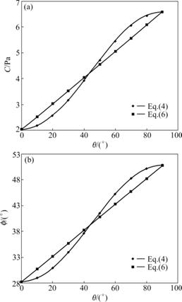
Fig.3 Relationship between shear strength and ��: (a) Cohesion C; (b) Friction angle ![]()
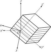
Fig.4 Local and global coordinate systems
the foliated plane is taken as x��y�� plane, and the normal direction of the foliated plane is taken as z�� axis, then the elastic matrix in the local coordinate system x��y��z�� is written as [17].
![]()
 (7)
(7)
where M=E1/(1+��1)(1-��1-2n��22); n=E2/E1; G1=E1/ 2(1+��1); E1 and ��1 are the elastic modulus and Poisson ratio in the foliated plane, respectively; and E2, G2 and ��2 are the elastic modulus, the shear modulus and Poisson ratio in the direction perpendicular to the foliated plane, respectively.
Stresses and strains are transformed from the local coordinate system x��y��z�� into the global coordinate system xyz, we get
![]() (8)
(8)
where ��, �� and D are stress tensor, strain tensor and elastic matrix in the global coordinate system, respectively, and
![]() ;
;
L=
 ;
;
L is the coordinate transformation matrix; li, mi and ni (i=1, 2, 3) are cosines of the angles between the axes of the local and global coordinate systems.
3.2 Failure criterion
For the layered rock and stress state presented in Fig.5, if Mohr-Coulomb criterion is applied, a shear surface will occur in ��1-��3 plane, we have
![]() (9)
(9)
and
![]() (10)
(10)
![]() (11)
(11)
where �� and �� are shear and normal stresses, respectively; ��1 and ��3 are major and minor principal stresses, respectively; and �� is angle between the failure surface and ��3 direction.
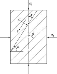
Fig.5 Stress state and foliated planes
Substituting Eq.(10)-(11) into Eq.(9) leads to a yield function as:
![]()
![]() (12)
(12)
After a transformation, Eq.(12) becomes [18]
![]()
![]() (13)
(13)
and
![]()
![]()
![]()
![]()
where J1 and J3 are the first and third stress invariants, respectively; J��2 is the second invariant of the deviatoric stresses, ��x, ��y and ��z are normal stresses in x, y and z directions, respectively; �ҡ�x, �ҡ�y and �ҡ�z are deviatoric stresses in x, y and z directions, respectively; ��xy, ��yz and ��xz are shear stresses in xy, yz and xz planes, respectively; and �� is Lode angle.
When angle �� between the failure surface and ��3 axis and the corresponding C(��) and ![]() are known, the plastic matrix can be computed as
are known, the plastic matrix can be computed as
 (14)
(14)
where H is a hardening function.
It is necessary to point out that if the rock is an isotropic one, its C and ![]() are constants, so there is ��=��/4+
are constants, so there is ��=��/4+![]() when the failure happens [19]; but here the rock is a transversely isotropic one, C and
when the failure happens [19]; but here the rock is a transversely isotropic one, C and ![]() are functions of the orientations with respect to the foliated plane, so angle �� and the corresponding C and
are functions of the orientations with respect to the foliated plane, so angle �� and the corresponding C and ![]() cannot be determined explicitly when the rock breaks. For this reason a search-trial method was put forward as follows.
cannot be determined explicitly when the rock breaks. For this reason a search-trial method was put forward as follows.
In the local coordinate system shown in Fig.6, it is assumed that a shear failure surface is produced, and its normal cosines are lx, mx and nx. As the normal is in ��1-��3 plane, the angles between the normal and axes are T1, T2 and 0, respectively, so this results in:
 (15)
(15)
where A=cos T1 and B=cos T2.
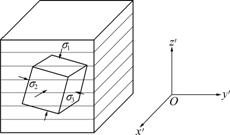
Fig.6 Layered rock and x��y��z�� coordinate system
Solving the normal cosines from Eq.(15), we have
 (16)
(16)
where ![]()
![]()
![]() b2=
b2=
![]() and nx is the cosine of angle between the
and nx is the cosine of angle between the
normal of the shear failure surface and z�� axis (rotationally elastic symmetry axis), so it leads to
![]() (17)
(17)
Then, according to the relationship among C, ![]() and �� in Eq.(3), C and
and �� in Eq.(3), C and ![]() may be calculated. But usually, {lx, mx, nx} are unknown beforehand. For this purpose a search-trial method is employed, that is, let angle �� change from 0? to 90?, and for every ��f, Ai=cos T1i and Bi=cos T2i are known, so nxi and ��i can be determined, and Ci and
may be calculated. But usually, {lx, mx, nx} are unknown beforehand. For this purpose a search-trial method is employed, that is, let angle �� change from 0? to 90?, and for every ��f, Ai=cos T1i and Bi=cos T2i are known, so nxi and ��i can be determined, and Ci and ![]() are obtained.
are obtained.
Using ![]() to find angle ��f corresponding to the maximum value of fi, the surface with ��f is the real or potential shear failure surface to be evaluated. This work can be done by the computer easily.
to find angle ��f corresponding to the maximum value of fi, the surface with ��f is the real or potential shear failure surface to be evaluated. This work can be done by the computer easily.
4 Calculation examples
It is assumed that the longitudinal axis of a tunnel, whose orientation is ��0=0?, is z axis of a global coordinate system, and the strike and dipping angles of the foliated plane of a layered rock around the tunnel are ��=45? and ��=45?, respectively, so we have [20]:
![]()
![]()
![]()
![]()
![]()
![]()
![]()
![]()
![]()
The cross-section of the tunnel is a rectangular one with a size of 10 m��10 m. The thickness of the overburden is 20 m. For the cases of taking the rock as a transversely isotropic one and an isotropic one respectively, the numerical analyses by using the 3D elasto-plastic FEM code developed by the authors were carried out. The mesh for FEM and the mechanical parameters of rock are shown in Fig.7 and Table 1, respectively.
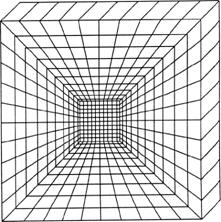
Fig.7 FEM mesh of rock
The displacement, plastic zones and contours of stresses in the plane perpendicular to z axis ��x, ��y obtained from the calculations are presented in Table 2 and Figs.8-9. From these data it can be seen that when the rock is a transversely isotropic one, the distributions of the displacements, plastic zones, ��x and ��y contours in the surrounding rock are non-axisymmetric along the tunnel��s vertical axis, and the quantity values are larger. For example, the range of resultant displacements of the tunnel periphery is 4.7-10.9 cm, and there are 148 plastic elements in the surrounding rock at the computation end. However, when the rock is an isotropic one, the distributions of the displacements, plastic zones, ��x and ��y contours in the surrounding rock are axisymmetric along the tunnel��s vertical axis, and the quantity values are smaller. For example, the range of resultant displacements of the tunnel periphery is 2.3- 6.7 cm, and there are 78 plastic elements in the surrounding rock at the computation end. There are distinct differences between the two cases, and the stability of the tunnel in transversely isotropic rock is relatively low.
Table 1 Mechanical parameters of rock

Table 2 Displacements at some points on opening boundary (Unit: cm)

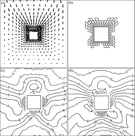
Fig.8 Calculation case for transversely isotropic rock: (a) Displacement vectors; (b) Plastic zones; (c) Contours of ��x (10-1 MPa); (d) Contours of ��y (10-1 MPa)

Fig.9 Calculation case for isotropic rock: (a) Displacement vectors; (b) Plastic zones; (c) Contours of ��x (10-1 MPa); (d) Contours of ��y (10-1 MPa)
So, it can be known that when a layered rock has very different mechanical properties in the directions parallel to and perpendicular to the foliated plane separately, and its occurrence shows certain geometrical relationship with the excavation factors (for example, the tunnel��s axial line), the dynamic state of the surrounding rock will be more complicated compared with the case of isotropic rock. So if a layered rock is met in the practice of rock mechanics and engineering, it is necessary to consider the anisotropy of mechanical behavior of the rock.
5 Conclusions
(1) The empirical expression of C and ![]() for layered rock is proposed and compared with a test result made by former researchers. The results show that both have a good agreement, indicating that the empirical expression is reliable.
for layered rock is proposed and compared with a test result made by former researchers. The results show that both have a good agreement, indicating that the empirical expression is reliable.
(2) The principles of 3D elasto-plastic FEM analysis are described, in which a layered rock is taken as a transversely isotropic one and the suggested empirical expression of C and ![]() is used. Among them the important thing is to adopt a search-trial method to find orientation angle �� of shear failure plane (or weakest shear plane) with respect to the major principal stress ��1 as well as C and
is used. Among them the important thing is to adopt a search-trial method to find orientation angle �� of shear failure plane (or weakest shear plane) with respect to the major principal stress ��1 as well as C and ![]()
(3) The calculation examples show that when a layered rock possesses obvious anisotropic mechanical behavior and its occurrence presents certain geometrical relationship with the excavation factors (for example, a tunnel��s axial line), the dynamic state of surrounding rock is more completed compared with the case of isotropic rock. So, this feature should be considered in numerical analysis and construction of a project.
References
[1] SERRANO A, OLALLA C. Ultimate bearing capacity of an anisotropic discontinuous rock mass. Part I: Basic modes of failure [J]. Int J Rock Mech Min Sci, 1998, 35(3): 301-324.
[2] LEE Y K, PIETRUSZCZAK S. Application of critical plane approach to the prediction of strength anisotropy in transversely isotropic rock masses [J]. Int J Rock Mech Min Sci, 2008, 45(3): 513-523.
[3] SAROGLOU H, TSIAMBAOS G. A modified Hoek-Brown failure criterion for anisotropic intact rocks [J]. Int J Rock Mech Min Sci, 2008, 45(3): 223-234.
[4] XU Wei-ya, ZHANG Gui-ke. Study on orthotropic equivalent strength parameters of jointed rock mass [J]. Chinese Journal of Geotechnical Engineering, 2007, (6): 806-810. (in Chinese)
[5] YANG Qiang, CHEN Xin, ZHOU Wei-yuan. Anisotropic yield criterion for jointed rock masses based on a two-order damage tensor [J]. Chinese Journal of Rock Mechanics and Engineering, 2005, 24(8): 1275-1282. (in Chinese)
[6] YU Tian-tang. Modeling of inherent anisotropy for geotechnical material [J]. Chinese Journal of Rock Mechanics and Engineering, 2004, 23(10): 1604-1607. (in Chinese)
[7] COLAK K, UNLU T. Effect of transverse anisotropy on the Hoek-Brown strength parameter ��mi�� for intact rocks [J]. Int J Rock Mech Min Sci, 2004, 41(3): 1045-1052.
[8] LYDZBA D, PIETRUSZCZAK S, SHAO J F. On anisotropy of stratified rocks: Homogenization and fabric tensor approach [J]. Computers and Geotechnics, 2003, 30(3): 289-302.
[9] PIETRUSZCZAK S, LYDZBA D, SHAO J F. Modelling of inherent anisotropy in sedimentary rocks [J]. Int J Solids Struct, 2002, 39(3): 637-648.
[10] USHAKSARAEI R, PIETRUSZCZAK S. Failure criterion for structural masonry based on critical plane approach [J]. J Eng Mech, 2002, 128(7): 769-778.
[11] PIETRUSZCZAK S, MROZ Z. On failure criteria for anisotropic cohesive-frictional materials [J]. Int J Numer Anal Meth Geomech, 2001, 25(3): 509-524.
[12] SMITH B, CHEATHAM B. Anisotropic compacting yield condition applied to porous limestone [J]. Int J Rock Mech Min Sci, 1980, 17(3): 159-165.
[13] NOVA R. The failure of transversely isotropic rocks in triaxial compression [J]. Int J Rock Mech Min Sci, 1980, 17(6): 325-332.
[14] JAEGER J C. Shear failure of anisotropic rock [J]. Geol Mag, 1960, 97: 65-72.
[15] ZHANG Yu-jun, TANG Yi-xing. 2-D FEM analysis for an underground opening considering the strength-anisotropy of the layered rock mass [J]. Chinese Journal of Geotechnical Engineering, 1999, 21(3): 307-310. (in Chinese)
[16] ATTEWELL B, SANDFORD R. Intrinsic shear strength of a brittle, anisotropic rock (I): Experimental and mechanical interpretation [J]. Int J Rock Mech Min Sci, 1974, 11(11): 423-430.
[17] ZHOU Wei-yuan. Higher rock mechanics [M]. Beijing: Water Conservancy and Power Press, 1990: 116-119. (in Chinese)
[18] OWEN J, HINTON E. Finite elements in plasticity: Theory and practice [M]. West Cross, Swansea: Pineridge Press Limited, 1980: 215-231.
[19] BRADY G, BROWN T. Rock mechanics for underground mining [M]. Beijing: Coal Industry Press, 1990: 83-84. (in Chinese)
[20] YU Xue-fu, ZHENG Ying-ren, LIU Huai-heng, FANG Zheng-chang. Stability analysis for surrounding rock masses of underground projects [M]. Beijing: Coal Industry Press, 1983: 505-508. (in Chinese)
Foundation item: Project(2010CB732101) supported by the National Basic Research Program of China; Project(51079145) supported by the National Natural Science Foundation of China
Received date: 2010-02-22; Accepted date: 2010-05-11
Corresponding author: ZHANG Yu-jun, PhD; Tel: +86-27-87198482; E-mail: yjzhang@whrsm.ac.cn
