
��������Ϲ����г���Ӵ�����
�ι���1, 2���Ϻ�־1������1������3��������2
(1. ���ϴ�ѧ ���繤��ѧԺ �����ܸ�����������ص�ʵ���ң����� ��ɳ��410083��
2. ���Ϲ�ҵ��ѧ ��е����ѧԺ������ ���ޣ�412007��
3. ��������ְҵ����ѧԺ ��Դ����ϵ������ ��̶��411104)
ժ Ҫ��
ԭ�����о���������Ϲ����еij���Ӵ����ԣ�����MATLAB����������Ӧ�ij������������� =1~3��Բ�����������������ʱ����ֳ���ĽӴ��켣���Ӵ������������״����ͨ������ֳ���Ӵ����ʵ����֤����ȷ�ԡ��о����������Բ�����ֵij����������ִ����ij���Ӵ�����������λ��Ӱ�첻�������ȶԳ���Ӵ������λ��Ӱ��ϴ�����Խ����Ӵ�����Խ����������ֳݵ��в���Խ�������������ִ��������ܡ�ͬʱʵ���������Ӵ��������״�����쾫��Ӱ�죬����Խ�ߣ�����Ӵ������������״Խ�ȶ�����������Խ�ߡ���ˣ���Ĵ����Ⱥߵ����쾫�ȶ��������ֵĴ�������������ġ�
�ؼ��ʣ�
������������Ӵ��켣������Ӵ���������������
��ͼ����ţ�TH132.4 ���ױ�־�룺A ���±�ţ�1672-7207(2013)01-0095-06
Tooth contact analysis of face gear meshing
HE Guoqi1, 2, YAN Hongzhi1, HU Wei1, HE Ying3, SHU Taoliang2
(1. State Key Laboratory of High-Performance Complex Manufacturing,
School of Mechanical and Electrical Engineering, Central South University, Changsha 410083, China;
2. School of Mechanical Engineering, Hunan University of Technology, Zhuzhou 412007, China;
3. Department of Resources Engineering, Hunan Vocational Institute of Technology, Xiantan 411104, China)
Abstract: According to the theory of face-gear meshing, a study was done on the tooth contact characteristics of the face-gear in meshing process. A meshing simulation of a face-gear and a cylindrical gear, with difference in the number of teeth =1-3, was conducted to obtain the contact path of face-gear tooth surface and the area and shape of contact region, with corresponding programs programmed by using MATLAB software. And the conclusion was right verified by the detection experiments on face-gear tooth surface contact. The results show that the difference in numbers of teeth of the cylindrical gear has little effect on the area and location of the contact area of the tooth surface in face-gear transmission, while the transmission ratio has a great impact on the location of the contact area of tooth surface. The larger the transmission ratio, and closer of the tooth contact area to the middle of the face gear teeth, the more improvement for the property of face-gear transmission. The area and shape of the tooth surface contact area is influenced by the manufacturing precision. The higher accuracy and more stabe, the area and shape of the tooth surface contact area bring about the higher quality of transmission. Therefore, large transmission ratio and high manufacture precision are beneficial to improve the quality of face-gear transmission.
Key words: face-gear meshing; contact path; contact area of tooth surface; transmission ratio
����ִ�����һ��Բ��������Բ���������ϵij��ִ�����������ɳߴ��������еĽ�����Բ��������ͬ��������ĵ��߾����ɼӹ����ɡ�������ڷ���-������������Ķ�����[1-2]ʹ���ں�����������������ս��ֱ�����е�Ӧ�þ���DZ�����ơ�����ֳ���Ӵ�������ָ����������ϵ��ֳݱ����ϽӴ��ߵĵ��ӡ��Ӵ�����Ĵ�С����״��λ�ò�������ӳ�˵������ֵ����쾫�ȣ�ͬʱ��ӳ�˳��ָ��İ�װ�ʹ�������[3]����Ӱ����ָ������ij���������ʹ������������������Ч�ʡ��������ۺϼ���ָ�꣺��ˣ�ͨ���ѳ���Ӵ�������Ϊ���۳��ִ�����̬���ܵ���Ҫ�� ��[4]��Ŀǰ������������������ԭ��������ֳ���Ӵ�ǿ�ȡ�������ֳ�����ǿ�ȡ��г��Լ�ĥ�ݼӹ��ȷ��濪չ��ʵ���о���Litvin��[1-2, 5-7]������ִ����Լ�����ֵij������ɡ��ӹ��������ṹӦ��������Ԫ��ģ�����ȷ���������о�����չ������ִ�����Ӵ����ۡ����������[8]�Ե�Ӵ�����ִ������ؽӴ������˷�������̫��[3]��Բ�����ֳ���Ӵ��ߺ۵���ʽ�����˷������о��˳�����Ӵ��ߵ�ʹ��������Ĺ�ϵ�����ݳ���Ӵ��ߺ��γɵ�ԭ��ȡ���Ӧ���������Ʒ�����������[4]�о�����������ִ����еij���Ӵ����ԣ��ó���Բ�����ֺ���������ֽӴ��㴦�����ʵı仯���ɡ�Ȼ����Ŀǰ�й���������Ϲ����г���Ӵ�������Բ�����ֵij�����������֮��Ĺ�ϵ���о��������٣�Ϊ�ˣ���������ͨ����������Ϲ����г���Ӵ�����ķ��漰����ֳ���Ӵ����ʵ�飬�о�Բ�����ֳ���������ȼ����쾫�ȶ���������ϽӴ������Ӱ�졣
1����������ϳ���Ӵ�������
1.1 ����ֳ��淽��
����ֵļӹ����ý�����Բ�����ֵ��߾����ɷ��ӹ����ɣ���ӹ�ʾ��ͼ��ͼ1��ʾ�����÷��ɷ��ӹ������ʱ�������߳������������ְ��ո����Ĵ������˶��������߳���İ����漴Ϊ����ֵij��档����淽���Ǹ��ݳ��ֵ�����ԭ�����ɵ��ߵij��淽���Ƶ��õ�[9-10]��
����ֳ��淽�̵��Ƶ����Ը���Ϊ���¼�����(1) ���뵶�߹̽������ϵSm�У�ȷ�����߳��� ��(2) Sm�еĵ��߳�������ת����������ֹ̽��������S2�У��γ����ݵ���ת��
 �仯�ĵ��������飻(3) ��S2�������У�������������Ϸ��������������ֳ���
 ������ּӹ������и�����ϵ�Ĺ�ϵ��ͼ2��ʾ��

ͼ1 ����ּӹ�ʾ��ͼ
Fig.1 Schematic diagram of face-gear machining

ͼ2 ����ּӹ�ʱ������ϵ
Fig.2 Coordinate system of face-gear machining
���߽����߳��� �ķ���Ϊ[11]��
 (1)
(1)
ʽ�У�rbmΪ���߽����ߵĻ�Բ�뾶��umΪ���߳���ijһ�����������������������裬�Ե��߳�����������ת����������ֵij�������Ϊ[12] ��
 (2)
(2)
ʽ�У� ��������ֳݵ���һ�����淽�̿�ͨ���ı�
 ���ķ��ŵõ���
1.2 ��������ϵ�Ӵ��켣����
�������ϴ�����Բ�����ֺ�����ֵ�ת�Ƿֱ�Ϊ ��
�� ��Բ����������̶�����ϵS10�еij��淽�̺ͳ��淨�߷���Ϊ��
 (3)
(3)
ʽ�У�  ��
�� Ϊ��Բ�����ֵĶ�����ϵS1����̶�����ϵS10������ת������
 Ϊ��ȥ����4�к͵�4�еľ���
 ��
��

�� ����ʽ(3)��Բ�������ϵ����Ϲ켣����
 Ϊ[13]��

 (4)
(4)
��������ת���Ĺ�ϵ��֪�������������ϵS2�ϵ����Ϲ켣����Ϊ[13]��

 (5)
(5)
1.3 ����ִ����Ӵ����������ȷ��
������ִ����У�Բ��������2������ƽ���ϵ����ʰ뾶�ֱ�Ϊ ��
�� ������ֽӴ��㴦��2������ƽ���ϵ����ʰ뾶�ֱ�Ϊ
 ��
�� ��������ƽ���빫����Ľ��߷ֱ�Ϊ����(x1��y1)��(x2��y2)�����ڵ�Ӵ�������ִ����������ϵ㴦�γɽӴ���Բ�����ݽӴ��������ʺ��������嵯��ϵ����Ӵ���Բ����Ĺ�ϵ���Ӵ�������Բ���̰���
 ��
�� �ֱ�Ϊ[14-15]��
 (6)
(6)
ʽ�У� ��Ei (i=l, 2)�ֱ�Ϊ2�����ֲ��ϵIJ��ɱȺ͵���ģ����ϵ��u��vΪ��Բ���ֺ��������ֱ�Ϊ���ϵ㴦��Բ�����ֳ����2�������ʣ����ֱ�Ϊ���ϵ㴦������ֳ������������[14-15]��


 (7)
(7)
�����������Բ�̰뾶��ȷ���Ӵ�����������
2 ��������ϳ���Ӵ�����
2.1 ��������ϲ���
��������ϲ���Ϊ��ģ��m=5��ѹ���� =20�㣬����ֳ���N2=40���ӹ�����ֵĵ��߳���NS=20�����ǵ�Ҫʹ�����ʵ�ֵ�Ӵ���Բ�����ֵij���Ӧ�ñȼӹ������ʱ�ĵ��߳�����1~3����[1-4]����ˣ�������Բ�����ֳ���N1�ֱ�Ϊ17��18��19��ʩ������������Ft=1 kN�����������ʱ����Ӵ�������з��档
2.2 ����Ӵ��켣����
����MATLAB����������Ӧ�ij���ֱ��Բ�����ֵij���Ϊ17��18��19�����Ϊ40�����������ʱ�ij���Ӵ����з��棬���������켰��װ����Ӱ�죬��������������ҳ����ϽӴ���λ������ԳƵģ���ˣ����ýӴ��㷽�̣��Դ����������������ϵĽӴ���λ�ý��з��档��������ϵĽӴ��켣����(5)����ʾ�ĽӴ��켣 ��1����Ϊ�����Ŀռ����ߣ���ͼ3��ʾ����ͼ3�ɼ�����ͬ������Բ����������������ϵij���Ӵ��켣�ڳ����λ�ü���û�б仯��
2.3 ����Ӵ������
��Բ�����ֵij���Ϊ17�ĽӴ��켣����ѡ��7�����ϵ��ʵ�ʽӴ���Բ����з����������ͼ4��ʾ��ͨ�������Ӵ�������漸�ι�ϵ��֪���������֮������ͬ����ĵ��ڹ������Ͻ��γ���������Բ������[9]��ͼ4�г���Ӵ����������ϵ�Ϊ��Բ�����ġ�������Բ�Ķ������ܴ���ˣ��Ӵ������Ϊһ���߶Ρ��Ӵ�������ӳݶ����ݵ�Ϊ1���߶Σ��ڳݳ�����������ʱ�뷽����ת���ڳݸ��в��ﵽ����ڳݶ�λ�ô���С����ͼ4�ɼ�����������ڱ�Ե�Ӵ����������ִ�����˵�Dz����ģ�Ӧ�������⡣
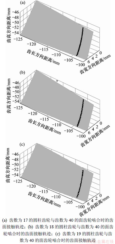
ͼ3 ����Ϊ40����������ϳ���Ӵ��켣������
Fig.3 Simulation results of tooth contact trajectory of 40-tooth face-gear meshing
2.4 ������
������ֳ�����Ϊ100���������������������¶����������ʱ����Ӵ��켣���з��棬������ͼ5��ʾ����ͼ5�ɼ����ı�����ִ�������Ӱ�����Ӵ��켣���Ҵ�����Խ�Ӵ��켣Խ���������в��������������Խ������Ҳ����˵����Ĵ����������ڸ�������ֵĴ�������������˵������ִ����ʺϴ��ȵij��ϡ�
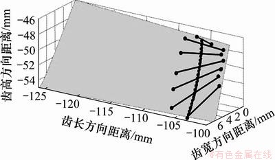
ͼ4 ����Ϊ40����������ϳ���Ӵ��Ӵ����������
Fig.4 Simulation of tooth contact area of 40-tooth face-gear meshing
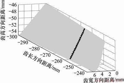
ͼ5 ����Ϊ100����������ϳ���Ӵ��켣������
Fig.5 Simulation of tooth contact trajectory of 100-tooth face-gear meshing
3 ����ֳ���Ӵ�����ʵ��
3.1 ����ֳ���Ӵ�������
������������ֵIJ����ӹ�����Ӧ������ּ�Բ�����֣�ʵ�����Ĵ��ڽ�������������YD9550���������Ͻ��С�YD9550�͵��������Զ����ֹ�����������ģ�����ύ��Ϊ90��ij��ָ��Ӵ����ȡ���װ�ࡢ�ݲ��϶������ƽ���Եȡ�
3.2 ���ְ�װ
��Ϳ�к쵤�۵����Բ�����ֺ���������üо߷ֱ�װ�ڻ�����2�������ϣ������ᰲװԲ�����֣��Ӷ��ְ�װ����֡����������������ƫ�þ���������������н���ʹ���������ϡ�����������ʹ�Ӷ������ڵ��ƶ��£���������ֱ����(���ٺ͵���)����ת�����������к�ó���ĽӴ����ȡ�������ƽ���Եȡ�
3.3 ����Ӵ�������
3.3.1 �����ֳ�����Գ���Ӵ������Ӱ��
Ϊ�˼��Բ�����ֳ�������������ϽӴ������Ӱ�죬�ֱ���ó�����Ϊ1~3(Բ�����ֳ���Ϊ17��18��19)��3��Բ������������ֽ������ϣ�3��Բ�����ֵĽӴ��ߺ���ͼ6��ʾ����3��Բ�����ֵĽӴ��ߺ�������Բ�����ֵij�������������ϳ���Ӵ��ߺ۵�λ�úʹ�С����û��Ӱ�졣ͼ7��ʾΪ�������Ϻ������ֳ���Ӵ��ߺۣ�������ǰ����е�����ֳ���Ӵ����������һ�¡�
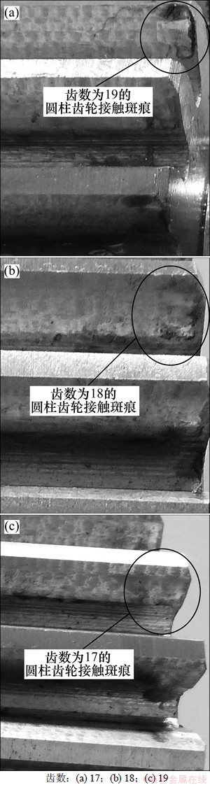
ͼ6 ����Ϊ17��18��19��Բ�����ֵij���Ӵ��ߺ�
Fig.6 Contact scars of cylindrical gears with teeth number of 17, 18 and 19, respectively
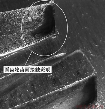
ͼ7 ����ֵij���Ӵ��ߺ�
Fig.7 Tooth contact scars of face-gears
3.3.2 �������ֵ����쾫�ȶԳ���Ӵ������Ӱ��
�ֱ���ϳ�ݺ�ĥ��2�ַ����ӹ���2������֣�ϳ�ݺ������־��ȵȼ�Ϊ7����ĥ�ݺ������־��ȵȼ�Ϊ6�����ֱ�2�־��ȵ�����ְ�װ��YD9550���������ϣ������Ϊ18��Բ�����������ϣ����г���Ӵ���⡣������30 min�ֱ���2����ֳ���Ӵ������ͼ8��ͼ9��ʾ�ֱ�Ϊ��ϳ�ݺ�ĥ�ݵ�����ֳ���Ӵ��ߺۡ���ʵ��������ͼ8�е�����3������ĽӴ��ߺ�(A��B��C��ָ����)�Ĵ�С����״����һ������ͼ9�е�����3������ĽӴ��ߺ�(A��B��C��ָ����)�Ĵ�С����״ȴ�dz����ƣ��ɼ�������ֳ���Ӵ�����Ĵ�С����״����ֵ����쾫�ȹ�ϵ���У�����Խ�ߣ�����Ӵ�����Խ�ȶ�����������Խ�ߡ�
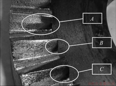
ͼ8 ��ϳ�ݺ�����ֳ���Ӵ��ߺ�
Fig.8 Tooth contact scars of milled face-gear
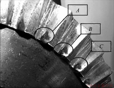
ͼ9 ��ĥ�ݺ�����ֳ���Ӵ��ߺ�
Fig.9 Tooth contact scars of grinded face-gear
4 ����
(1) ��Ӵ�������ִ����У�����Ӵ�Ϊһ��Բ�����ڳݸ��в��Ӵ���������ﵽ����ڳݶ�λ�ô��Ӵ����������С��
(2) ��Ӵ�������ִ�������Ӵ�����Ĵ�С��λ����Բ�����ֵij������ϵ����ͬ������Բ���������ϰߺ۵�λ�á���С����״ʮ�����ơ�
(3) ����ֳ���Ӵ�����Ĵ�С����״��������쾫���йأ�����Խ�ߣ�����Ӵ�����Խ�ȶ�����������Խ�ߡ�
(4) ����ִ����Ĵ����ȶԳ���Ӵ������λ��Ӱ��ϴ�����Խ����Ӵ�����Խ����������ֳݵ��в�������������ִ����������������ġ���ˣ��ڲ�������ִ����ij��ϣ�Ӧ���Ǵ�Ĵ����ȣ��Ա��������Ե�Ӵ���
�ο����ף�
[1] Litvin F L, Alfonso F, Hawkins J M, et al. Design, generation and tooth contact analysis (TCA) of asymmetric face-gear drive with modified geometry[R]. Cleveland: NASA TM 210614, 2001: 1-15.
[2] Litvin F L, Zhang Y, Wang J C, et al. Design and geometry of face-gear drives[J]. Transactions of the ASME, Journal of Mechanical Design, 1992, 114(4): 642-647.
[3] ��̫��. ���ִ����еij���Ӵ��ߵ��������������[J]. ��е����, 2009, 33(3): 114-118.
LUO Taijing. Analyses and control method of the gear tooth contact pattern in gear drive[J]. Journal of Mechanical Transmission, 2009, 33(3): 114-118.
[4] ����, ������. ����ֵij���Ӵ����Է���[J]. ��е�����о�, 2009, 38(3): 10-12, 29.
HOU Yin, ZHU Rupeng. Research on tooth contact analysis of orthogonal face gear[J]. Machine Building Automation, 2009, 38(3): 10-12, 29.
[5] Handschuh R, Lewicki D, Bossler R. Experimental testing of prototype face-gears for helicopter transmissions[R]. Solihull: NASA Technical Memorandum 105434, 1992: 1-10.
[6] Litvin F L, Wang J C, Bossler R B, et al. Application of face-gear drives in helicopter transmissions[R]. Scottsdale: NASA Technical Memorandum 105655, 1991: 1-10.
[7] David G L, Robert F H, Gregory F H, et al. Evaluation of carburized and ground face gears[R]. Montreal: NASA TM209188, 1999: 1-10.
[8] ��������, ������. ����ִ����ij��ؽӴ�����[J]. �Ͼ����պ����ѧѧ��, 2010, 42(2): 219-223.
LIZHENG Minqing, ZHU Rupeng. Load tooth contact analysis on face gear driver[J]. Journal of Nanjing University of Aeronautics & Astronautics, 2010, 42(2): 219-223.
[9] Kissling U, Beermann S. Face gears: Geometry and strength[J]. Gear Technology, 2007(1): 54-61.
[10] Barone S, Borgianni L, Forte P. Evaluation of the effect of misalignment and profile modification in face gear drive by a finite element meshing simulation[J]. Transactions of ASME, Journal of Mechanical Design, 2004, 126: 916-924.
[11] Guingand M, de Vaujany J P, Jacquin C Y. Quasi-static analysis of a face gear under torque[J]. Computer Methods in Applied Mechanics and Engineering, 2005, 194: 4301-4318.
[12] Litvin F L, Gonzalez-Pei L, Fuentes A, et al. Design and investigation of gear drives with non-circular gears applied for speed variation and generation of functions[J]. Computer Methods in Applied Mechanics and Engineering, 2008, 197: 3783-3802.
[13] ZHANG Jinliang, FANG Zongde, CAO Xuemei, et al. The modified pitch cone design of the hypoid gear: manufacture, stress analysis and experimental tests[J]. Mechanism and Machine Theory, 2007, 42: 147-158.
[14] Zanzi C, Pedrero T I. Application of modified geometry of face gear drive[J]. Computer Methods in Applied Mechanics and Engineering, 2005, 194: 3047-3066.
[15] Simon V. Computer simulation of tooth contact analysis of mismatched spiral bevel gears[J]. Mechanism and Machine Theory, 2007, 42: 365-381.
(�༭ �²ӻ�)
�ո����ڣ�2012-02-10�������ڣ�2012-04-23
������Ŀ�������ص�����о���չ�滮(��973���ƻ�)��Ŀ(2011CB706800)������ʡ�ߵ�ѧУ��ѧ�о���Ŀ(12A038)������ʡ��Ȼ��ѧ����������Ŀ(11JJ5028)
ͨ�����ߣ��Ϻ�־(1964-)���У����ϰ����ˣ���ʿ�����ڣ���ʿ����ʦ���������ֻ����������뼼���о����绰��0731-88876612��E-mail: yhzcsu@163.com
ժҪ���������������ԭ�����о���������Ϲ����еij���Ӵ����ԣ�����MATLAB����������Ӧ�ij�������������=1~3��Բ�����������������ʱ����ֳ���ĽӴ��켣���Ӵ������������״����ͨ������ֳ���Ӵ����ʵ����֤����ȷ�ԡ��о����������Բ�����ֵij����������ִ����ij���Ӵ�����������λ��Ӱ�첻�������ȶԳ���Ӵ������λ��Ӱ��ϴ�����Խ����Ӵ�����Խ����������ֳݵ��в���Խ�������������ִ��������ܡ�ͬʱʵ���������Ӵ��������״�����쾫��Ӱ�죬����Խ�ߣ�����Ӵ������������״Խ�ȶ�����������Խ�ߡ���ˣ���Ĵ����Ⱥߵ����쾫�ȶ��������ֵĴ�������������ġ�
[3] ��̫��. ���ִ����еij���Ӵ��ߵ��������������[J]. ��е����, 2009, 33(3): 114-118.
[4] ����, ������. ����ֵij���Ӵ����Է���[J]. ��е�����о�, 2009, 38(3): 10-12, 29.
[8] ��������, ������. ����ִ����ij��ؽӴ�����[J]. �Ͼ����պ����ѧѧ��, 2010, 42(2): 219-223.
[9] Kissling U, Beermann S. Face gears: Geometry and strength[J]. Gear Technology, 2007(1): 54-61.
