
Trans. Nonferrous Met. Soc. China 29(2019) 1653-1664
Wear modes in open porosity titanium matrix composites with TiC addition processed by spark plasma sintering
I. FARIAS1, L. OLMOS2, O. JIMENEZ1, M. FLORES1, A. BRAEM3, J. VLEUGELS3
1. Departamento de IngenierIa de Proyectos, Universidad de Guadalajara, 45100, Zapopan, Jalisco, MExico;
2. Instituto de Investigaciones en Ciencias de la Tierra - INICIT, Universidad Michoacana de San Nicolas de Hidalgo, 58060, Morelia, Michoacan, MExico;
3. KU Leuven Department of Materials Engineering, Kasteelpark Arenberg 44, B-3001 Heverlee, Belgium
Received 4 December 2018; accepted 17 May 2019
Abstract:
This work focused on the influence of TiC reinforcing particles on the tribological properties of titanium matrix composites (TMCs) with open porosity, processed by spark plasma sintering (SPS). Materials composed of an equimolar mixture of Ti and TiH2 with 0, 3, 10 and 30 vol.% of TiC were sintered at 850 ��C. Nanoindentation and wear tests were carried out to assess the nanohardness and the wear resistance in a tribometer with a reciprocating sliding ball-on-flat configuration. Results showed a nanohardness increment from 5 to 14 GPa with increasing TiC content. The coefficient of friction (CoF) showed a minimum of 0.2 for 10% TiC grade, which also showed the lowest wear rate. For the low TiC content sample, adhesive wear with severe plastic deformation was identified. Meanwhile, medium content TiC sample showed a mechanical mixed layer (MML), whereas high TiC content composite showed abrasive as the main wear mechanism. In conclusion, the wear mechanisms, CoFs and wear volume changed with TiC content.
Key words:
porous titanium; spark plasma sintering; wear; titanium matrix composites;
1 Introduction
Titanium and its alloys combine interesting chemical, physical and mechanical properties such as high corrosion resistance, low density (4.5 g/cm3) and relatively low elastic modulus (110 GPa) which make them suitable for chemical, aerospace, marine, sports and biomedical applications [1]. On the other hand, metal matrix composites (MMCs) and titanium matrix composites (TMCs) with reinforcing particles embedded in a matrix have been investigated with the purpose to enhance their performance in service. TMCs offer attractive mechanical properties, including high specific strength, thermal stability, erosion, corrosion wear and creep resistance [2,3]. These composites have been proposed for advanced applications where monolithic materials are insufficient, such as aerospace, gears, turbine blades, rotors, missile housing, tubing, and engine parts, in conjunction with commercial applications such as medical implants, high-performance sporting and automotive components [4,5].
Additionally, several kinds of composites have been processed by spark plasma sintering (SPS) which is a relatively novel sintering technique used for materials consolidation. SPS involves volumetric Joule heating by a pulsed DC current passing through a graphite die/punch set-up that contains the starting powder. The process permits simultaneously a high pulsed DC current (10 kA) flow at low voltage (10 V), in combination with a uniaxial pressure, resulting in high density materials in a short period of time. Therefore, in comparison to conventional sintering methods such as hot isostatic pressing, hot pressing, microwave sintering or high temperature extrusion, grain growth in SPS can be minimized [6,7]. Furthermore, different factors contribute to fast sintering during SPS such as a high heating rate, volumetric Joule heating, and the pulsed on/off current flow through the powder compact [8,9]. These processing parameters have the advantage to develop materials such as intermetallic, refractory, nanostructured, functionally graded and non-equilibrium materials [10], which often showed advanced mechanical properties such as ultra-high yield strength (2050 MPa) and large plastic strain (19.7%) [11].
On the other hand, mixtures of Ti and TiH2 were used to specifically obtain porous materials, with an optimal composition of Ti-40 wt.%TiH2, and a maximum open porosity of 23% [12]. In addition, fine titanium compounds such as TiH2 also offer the advantage of a good distribution within the compact enhancing sintering and reducing the cost of raw materials [13]. During sintering, the hydrogen is completely or partly removed by dehydrogenation in the lower temperature range (<600 ��C), resulting in a high purity and reactive fine Ti powder that enhances densification [14-16]. Even if TiH2 is not completely removed during processing, TiH2 is easily removed by annealing in vacuum due to its high diffusivity, permitting temporally usage as an alloying element [17,18].
Knowing the poor tribological properties of titanium and its alloys [19,20], TMCs and MMCs have been particle-reinforced with refractory materials for enhancing the wear resistance. Varying the amount of reinforcing particles and the sliding velocity in wear tests allows to delay the transition to a severe wear regime, and thus, the wear resistance can be improved [21,22]. Although many studies reported a better wear resistance accompanied with a low coefficient of friction [23-26] upon adding secondary phase particles, RAM PRABH et al [27] pointed out that ceramic particles could act as an abrasive agent when the bonding between matrix and reinforcing particles is weak. Therefore, the wear resistance of composite materials could be influenced by several factors such as the size, volume and geometry of the secondary phase particles, counterpart material, load, microstructure, atmosphere and humidity. While most of the investigations agree on the beneficial use of composite materials for wear applications, it is not entirely clear how the wear modes change as a function of the TiC reinforcement content. The aim of this work is to analyze the wear mechanisms of TiC particle-reinforced Ti composites processed by means of SPS at a low temperature of 850 ��C from a mixture of commercially pure (C.P.) Ti and TiH2 with TiC particles addition. A possible correlation between the evolution of the total wear volume and the hardness due to TiC addition was investigated.
2 Experimental
2.1 Materials and sample preparation
An equimolar powder mixture of C.P. Ti (Grade 2, Raymor AP&C) with a particle size <45 ��m and a mean size of 17.7 ��m and TiH2 (grade VM, Chemetall) with a D50 of 10.6 ��m, was used as the matrix, without and with addition of 3, 10 or 30 vol.% of TiC (99.9%, Atlantic Equipment Engineers) with a mean size of 4.21 ��m as reinforcement phase. Figure 1 shows the morphology of the starting powders, as obtained from SEM images.
The powders were weighed and manipulated in a glove box under a protective Ar atmosphere and the polyethylene containers with the powder mixture were sealed to avoid oxidation. The mixture was dry-mixed on a multidirectional turbula mixer (WAB, Switzerland) at 75 r/min during 5 h. 10 g of the prepared powder mixture was poured into a graphite cylindrical die with an inner and an outer diameter of 32 and 66 mm, respectively. Sintering was performed using SPS (HP D25/1, FCT Systeme, Frankenblick, Germany) in a vacuum of 400 Pa with a pulse/pause duration of 10/5 ms. The SPS sintering parameters are shown Fig. 2(a).
2.2 Sample preparation and microstructural characterization

Fig. 1 SEM images of starting powders
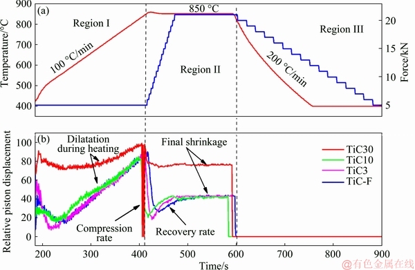
Fig. 2 SPS processing parameters (a) and densification behavior during SPS process (b)
The SPS materials are referred to as TiC-free (TiC-F), TiC3, TiC10, and TiC30 in accordance to their TiC content. SPS samples were ground and polished using conventional metallographic preparation in order to obtain mirror finished surfaces with an average roughness of 50 nm. Once being polished, the samples were etched with Kroll��s reagent for microstructural analysis. The identification of the crystalline structure was done through X-ray diffraction (PANanalytical, Empyrean diffractometer) with Cu K�� radiation (��=1.54  ) at 40 kV and 30 mA in a Bragg-Brentano configuration in the 2�� range of 30��-75��, with a step size of 0.02 (��)/s. Quantitative phase analysis was conducted using Rietveld refinement with MAUD software. The microstructure of the TMCs was characterized by field emission scanning electron microscopy (FE-SEM, TESCAN, Mira 3 LMU Microscope) coupled with an energy dispersive X-ray spectrometer (Bruker, XFlash 6|30) for elemental and mapping analysis. The density of the SPS materials was measured according to the Archimedes principle in distilled water at 20 ��C on a Sartorius analytical balance with a precision of 0.1 mg. The theoretical density was calculated assuming the rule of the mixtures based on the XRD phase composition analysis, using a theoretical density of 4.5, 3.76 and 4.93 g/cm3 for Ti, TiH2 and TiC, respectively. In addition, the samples were encapsulated into a lacquer of known density in order to avoid water absorption during immersion according to the following expression:
 (1)
(1)
where ��SL is the density of the sample and lacquer,  is the water density, wSL is the mass of sample and lacquer and wSL(H2O) is the mass of sample and lacquer in water. Finally, in order to obtain the theoretical density of the porous sample ��s, the following equation was used:
 (2)
(2)
where wL and wS are the masses of the lacquer and non-encapsulated sample, respectively, and ��L is the known density of the lacquer.
2.3 Hardness evaluation
The Vickers hardness of the open porosity SPS material was measured, while nanoindentation tests were carried out to punctually measure the bulk material without the influence of porosity. The Vickers hardness was measured under a constant load of 300 g and a dwell time of 15 s by means of a FutureTech FM-800 microdurometer. On the other hand, nanohardness was measured using a Nanovea CB500 nanoindenter at a maximum force of 80 mN in a programmed square matrix of 4��4 and 60 ��m between indentations. The reduced elastic modulus, Er, and hardness, H, were calculated from the loading-unloading curve and maximum load, respectively, according to the Oliver and Pharr method [28]:
 (3)
(3)
and
 (4)
(4)
where dP/dh is the slope at the start of the unloading curve, A is the projected area of the Berkovich indenter on the sample, �� is a geometric factor correction for the Berkovich indenter (��=1.034), and Pmax is the maximum load used.
The reduced elastic modulus is the elastic property combination of the indenter tip and sample as follows:
 (5)
(5)
where v and E are Poisson ratio and elastic modulus of the bulk material, respectively; vt and Et are Poisson ratio and elastic modulus of the indenter.
2.4 Wear testing
Reciprocating sliding wear tests were performed on a CETR UMT-2 microtribometer with a ball-on-flat configuration at a constant load of 2 N, a stroke length of 10 mm, a frequency of 1 Hz for 1800 s and 10 mm alumina ball counterpart (Redhill precision, 99.5% Al2O3) with an initial calculated Hertzian contact stress of 374 MPa. A metallographic microscope (Nikon eclipse MA100) was used to observe the worn surface of the Al2O3 ball after reciprocating testing. SPS samples were ground and polished using conventional metallographic techniques to obtain a mirror-like surface finish using a 0.05 ��m Al2O3 suspension. The samples were ultrasonically cleaned and dried in a muffle furnace at 95 ��C for 3 h prior to wear testing. The roughness and volumetric wear loss were measured through 3D optical profilometry by means of a FILMETRICS 3DProfilm equipment.
3 Results and discussion
3.1 Sintering behavior
Figure 2 shows the sintering evolution during the SPS process in which three different regions can be distinguished. The first region is influenced only by the temperature ramp, where dilatation of the powders occurred in all cases, leading to an expansion of the powder compact. The densification curves of the TiC-F, TiC3 and TiC10 composites are comparable, whereas the densification curve of the TiC30 is substantially different. In Fig. 2(b), the thermal expansion and final shrinkage of TiC30 are less pronounced. This discrete expansion is explained by the higher TiC content and its lower thermal expansion compared to TiC-F. The lower final shrinkage is due to the percolated network of TiC particles that inhibit plastic deformation of the powder compact, resulting also in higher residual porosity. A second region starts after 410 s, showing an increment of the force accompanied by a rapid piston displacement, i.e., densification, leading to a final shrinkage. Since the SPS TiC-F, TiC3 and TiC10 grades had a substantial amount of residual TiH2, whereas TiC30 was partially dehydrogenated, it is assumed that there was not enough time to complete the dehydrogenation. Moreover, since the H2 gas might be trapped in the closed porosity of the plastically deformed Ti matrix, the TiC30 presented a substantially higher amount of open porosity allowing a better evacuation of H2. Dehydrogenation of TiH2 occurs in the temperature range of 450-570 ��C in pressureless sintering conditions [29]. The third region begins with a rapid cooling rate and a progressive release of the piston pressure.
Table 1 summarizes the densification and recovery rate, along with the measured density. The reinforcing content accelerates the densification and recovery rate of the powder compact during sintering of TiC-F, TiC3 and TiC10. Therefore, in this study, the densification/ compression rate is driven by hard particles for content up to 10 vol.%. However, in TiC30, the percolation network due to the large fraction of hard particles hinders the densification during the compression process. BOUVARD [30] described that the densification process is driven by the soft particles when they reach their yield stress, while hard particles stop the densification process in mixtures of soft and hard particles under isotropic or quasi-isotropic pressure. Hard particles may create a percolation network, as in TiC30, due to the rearrangement during the compression process. If hard particles do not present plastic deformation or fragmentation, an increment in densification is not possible.
Table 1 Punch compression/recovery rates during SPS and relative density of SPS materials

3.2 Phase identification of composite compacts
Figure 3 shows the XRD patterns of the SPS materials with different TiC contents. Due to the rapid densification, Ti and TiH2 phases are present in all grades except TiC30, which apparently contains only Ti and TiC. The peaks corresponding to the TiC phase clearly become intenser with increasing TiC content in the starting powder mixture. Rietveld refinement of SPS processed composites did not show any shift of the TiC peak position. A direct comparison between PDF card for TiC (PDF#32-1383, 4.3274 ) and the lattice parameter of TiC in the composites ((4.3258��0.0002) ) showed no carbon dissolution in the Ti/TiH2 matrix. On the other hand, TiH2 was identified as fcc ��-TiH2 phase with a lattice parameter of (4.3999��0.0004) . The measured c/a ratio of the unit cell for the ��-Ti phase was 1.58, which matched well with the lattice parameters of the Ti reference card PDF#44-1294, confirming no change in the ��-Ti phase.
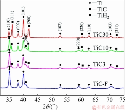
Fig. 3 X-ray diffraction patterns of SPS Ti matrix composites
Table 2 gives the numerical results of the Rietveld refinement compositional analysis. The TiH2 content clearly decreased with increasing TiC content, since the de-hydrogen process requires an open porous network for H2 evacuation during SPS processing [31]. Residual TiH2 has been reported for pressureless sintered cold isostatically pressed materials [12] and spark plasmasintering [32], since there is a difficulty of a complete dehydrogenation in short periods of time, even at elevated temperatures of 1300 ��C and 20 min holding time, as shown in Ref. [33]. Table 2 indicates that almost no TiH2 dehydrogenation occurred during SPS of the TiC-F and TiC3 materials, whereas 10 and 30 vol.% TiC addition allowed partial dehydrogenation in the applied SPS cycle.
Table 2 Constituent phases (vol.%) in SPS TiC-F, TiC3, TiC10 and TiC30 materials, as determined by XRD Rietveld analysis

3.3 Microstructural analysis
Figures 4(a-d) show backscattered electron (BSE) SEM images of the microstructure of the four TMCs materials. The matrix phase corresponds to gray-colored rounded C.P. Ti particles and randomly dispersed smaller grained TiH2 particles with the same contrast characteristics. The darker contrast reinforcing phases are the TiC ceramic particles. Additionally, residual porosity is present as a black contrast phase, concentrated, and surrounding the C.P. Ti particles.

Fig. 4 BSE SEM micrographs of TMC composites
Figure 4(a) shows a distribution of fine pores within the matrix, which could be formed by two routes: the released hydrogen from TiH2 and the remaining porosity after sintering. Figures 4(b-d) show coarser pores in comparison to those in Fig. 4(a). Here, pore formation is mainly due to the TiC addition and its low compressibility during SPS processing. The TiC particles and residual porosity are evenly distributed at the periphery of C.P. Ti particles. A fine acicular ��-phase in the C.P. Ti particles is presented, most probably as a result of the rapid cooling during the fabrication process. The low sintering temperature below the ��-�� transus temperature and the high cooling rate resulted in a microstructure resembles to that of C.P. Ti starting particles.
3.4 Hardness
Figure 5 shows the micro- and nanohardness data, along with the relative density of the investigated materials. The standard deviation on the hardness increased with increasing TiC content. This is explained by the increasing inhomogeneity of the composites as a result of the increasing quantity of the reinforcing particles and porosity, as shown in Fig. 4. On the other hand, the density is reduced with increasing TiC content in the composites. Although the microhardness is expected to increase with the reinforcing content, the average microhardness of TiC-F is higher than that of TiC3 and TiC10, which can only be attributed to the higher porosity as shown in Refs. [29,31]. Despite TiC30 has the lowest density, it showed the highest microhardness, clearly revealing that the higher TiC content counteracts the lower density. The nanoindentation results showed an almost linear increment in hardness as a function of the TiC volume fraction. The difference between the Vickers microindentation and nanoindentations hardness results is that nanoindentation is more punctual and uses lower loads, recording the composite as a bulk material. For the wear testing, the TiC content should therefore be considered to be more important than the residual porosity.
The microhardness of TiC-F, TiC3 and TiC10 is comparable to the microhardness HV0.2 value of 2.5 GPa reported for nanostructured (125 nm grain size) C.P. Ti [34]. TiC particles are not the only component that contributes to the hardness enhancement. Previous reports indicated that the hardness of TiH2 was also superior to that of C.P. Ti, i.e. 3.70 GPa vs 2.74 GPa [32]. Thus, the residual TiH2 content also contributed to an increased hardness of the TMCs after SPS. Figure 6 presents the nanoindentation load-displacement curves with a maximum applied load of 80 mN. The curves present a continuous and smooth profile during penetration of the tip which indicates the absence of cracks on the surface of the sample during testing. As expected, the penetration depth decreased with increasing reinforcement content.

Fig. 5 Nanoindentation, microhardness, and relative density as function of TiC content in particle-reinforced Ti matrix composites after SPS

Fig. 6 Nanoindentation load-displacement curves for TiC-F, TiC 3, TiC10 and TiC30
Table 3 summarizes the numerical data obtained from sixteen nanoindentations over the surface of each sample. SETOYAMA et al [35] pointed out that materials with an H/Er ratio around 0.05, such as ceramics, have an elastic behavior, whereas metals with a ratio below 0.006 deform plastically [36,37]. Furthermore, H3/Er2 (sometimes referred as yield pressure) reflects the resistance against plastic indentation [38]. Basically, high H3/Er2 ratios can be related to the wear resistance capacity of a material and consequently, the wear process is most of the time a result of plastic deformation. Additionally, H/Er and H2/Er2 ratios have been suggested as a good indicator of wear resistance, for instance, in the study of titanium base alloys [39]. Experimentally, the validation of the H/Er and H2/Er2 magnitudes and their relationship with wear, was developed by ATTAR et al [40] for Ti-TiB composites, proving that high values of yield strain and yield pressure are concomitant to increase the wear resistance.
3.5 Coefficient of friction and wear analysis
The coefficient of friction (CoF) during mechanical contact gives a numerical value of the resistance to movement in a tangential direction. Figure 7 shows the evolution of the CoF of the investigated composites. The CoF of TiC-F is below 0.18 during the initial 500 s, due to the low roughness and the native oxide film on the surface of the composite material provoked a smooth contact. Beyond 500 s, an increase to a constant value of 0.36 of the CoF is presented, with slight oscillations as a consequence of the breakdown of the oxide film, and the detachment of material which formed an oxide-based tribofilm. The CoF of TiC3 rapidly increased during the first 60 s to a stationary value of 0.36, comparable to that of TiC-F. The early increment in the CoF might be attributed to the effect of the reinforcing particles. The CoF of TiC10 reached a maximum during the first 100 s. Then, the CoF shifted to a continuous and steady low value of 0.20. Finally, the TiC30 composite presented the highest CoF, ~0.54, among all investigated materials. As expected, the CoF evolved according to the reinforcing phase content and residual porosity.
The wear track on TiC-F (Figs. 8(a-c)) shows abrasion and material adhesion as the main wear mechanisms with some oxidized material transfer located inside the grooves. In the absence of reinforcing ceramic particles, the wear test resulted in a partly-polished surface. Due to its microstructure shown in Fig. 4(a), TiC-F sample showed that due to applied normal force, asperities deformation increased exceeding the value of their elastic limit. Subsequently, the plastic deformation on asperities occurs until the total contact area increases enough to support the applied load. Thus, adhesive bonds are formed in the actual contact area, where the shear stress during movement cuts the joints. Therefore, the adhesive term specifies the formation of metal joints between the asperities of the material and the contact surfaces. For this case, abrasion caused plowing and cutting of soft material, resulting in plastic flow during tangential movement [41].
Upon adding reinforcing particles in TiC3, the presence of small-size debris is noticed in the wear track shown in Figs. 8(d, e). Moreover, the grooves seem to be narrow, but deeper as confirmed in Fig. 8(f).
Table 3 Numerical results from nanoindentation testing of TiC-F, TiC3, TiC10 and TiC30


Fig. 7 CoF evolution during reciprocating sliding of TiC-F, TiC3, TiC10 and TiC30 against Al2O3 sphere

Fig. 8 Wear track images and removed volume for TiC particle-reinforced Ti matrix composites after reciprocating sliding against Al2O3 sphere for 1800 s
Additionally, a higher degree of abrasion is observed in comparison to TiC-F, due to the addition of 3 vol.% TiC particles as they might act as abrasive debris pulling out material from the metal matrix during the reciprocating test, resulting in a higher wear rate of the composite [27,42]. The major wear volume and dispersion of the debris across the wear scar explained the early action of a third body element, which affected the CoF evolution with a sudden increment from 0.18 to 0.45 after hundred seconds.
Figures 8(g, h) show the formation of either a tribofilm or a mechanically mixed layer (MML) in the wear track of TiC-10. BISWAS [43] identified that the formation of new structures and materials in the interface is possible. This film has a major influence on the CoF and wear resistance since this can be protective or destructive depending on several factors. A tribofilm is chemically formed as a result of the interaction of the system with the environment and/or thermally activated by friction. During tribofilm formation, it has been shown that rubbing leads to the following phenomena: fine wear particles are oxidized by reaction with the environment and some fine particles at interphase are compacted and sintered, consequently, a protective film is formed and mild wear is established [44]. On the other hand, MMLs can be formed by a mechanical process with the addition of material from the counterpart, resulting in a new composite material formation. In order to know if there exists detachment material from the alumina ball, Fig. 9 shows the worn surface of the counterbody. The diameter (dashed line) and the damage on the Al2O3 sphere are directly related to the removed material volume from the TiC-F and TiC3 composites. The Al2O3 ball slid against TiC10 does not show a well-defined circular track and it presents the lowest damage. The Al2O3 sphere in contact with TiC30 shows a zone of concentrated damage with a low degree of penetration, which can be explained by the TiC particles in the composite acting as load carrier. Nonetheless, alumina ball had material removed in each case. Therefore, the partly delaminated oxide film shown in Fig. 8(g) could be considered as a new MML formed during sliding. Additionally, TiC reinforcing particles are important, providing good adhesion and mechanical interlocking in the film. STACHOWIAK [45] pointed out that the formation of TiO2 is usually due to the changes at the interface in the range of nanoscale to microscale. On the nanoscale, the surface material is released and reacts chemically to form the oxide, as confirmed in the EDS mapping shown in Fig. 8(h). The protective layer was mechanically and chemically formed at the interface, contributing to maintaining the so-called mild wear regime.
Recently, studies carried out on near-�� titanium and ��+�� alloys [46] concluded that the transition between mild and severe wear is characterized by the crack growth in the oxide film as a result of the local stress concentration. In this case, the MMLs presented cracking, followed by crack propagation, and finally delamination. The chosen testing parameters with normal force of 2 N and frequency of 1 Hz resulted in a mild wear regime since no transition to severe wear occurred. The initial CoF of TiC10 is 0.22, but was slightly reduced to 0.19 after the first 2 min with the formation of the protective MML. During the test, the Al2O3 ball slid on the MML film with a low tangential force leading to a smooth and relatively low CoF value which was continuously maintained at 0.19 during the whole reciprocating test. As a result, the TiC10 composite presented the lowest material loss, as shown in Fig. 8(i) and in Fig. 10.
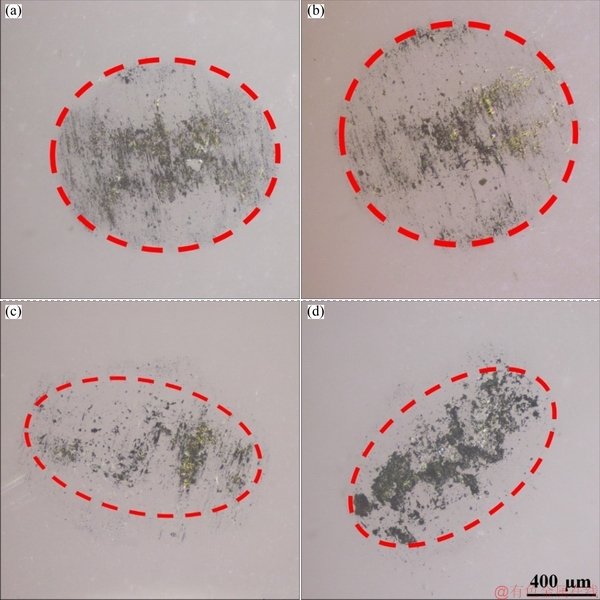
Fig. 9 Micrographs of Al2O3 ball surface after reciprocating testing against TiC-F (a), TiC3 (b), TiC10 (c) and TiC30 (d) for 1800 s
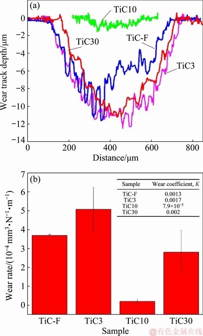
Fig. 10 Depth profile of wear track (a) and volumetric wear rate and wear coefficient (b) for TiC particle-reinforced Ti matrix composites reciprocatively-slid against Al2O3 sphere counterpart
The morphology of the worn surface of the TiC30 composite, presented in Figs. 8(j, k), shows that the probability of contact between removed TiC reinforcing particles and soft matrix alloy during the reciprocating test was highly recurrent. The hard particles, being the reinforcing phase, avoid the plastic deformation of the matrix due to their load-carrying capacity during rubbing, as evidenced in Fig. 9(d). The EDS mapping in Fig. 8(k) shows the TiC particles, colored in green, embedded in the matrix. This figure also shows a dark blue color corresponding to oxygen, confirming the formation of titanium oxide on the reinforcing phase. The TiC30 sample shows the second-best wear resistance among the investigated materials, as shown in Figs. 10(a, b).
In order to estimate the regime of the occurred wear, the wear coefficient (K) was calculated from ARCHARD��s equation [47]:
 (6)
(6)
where Q is the volume removed, L is the sliding distance, H is the hardness of the sample material, W is the normal load and K is a dimensionless constant. The calculated wear coefficient is reported in Fig. 10(b).
STACHOWIAK [45] identified mild and severe wear regimes under dry sliding conditions based on the K value. The mild wear regime has K values ranging from 10-6 to 10-4, whereas K ranges from 10-4 to 10-2 corresponding to the severe wear regime. Based on this, TiC30 has a major tendency to severe wear. However, it should be noted that one wear regime could present different wear mechanisms. For TiC30, the predominant wear mechanism was abrasion, mainly generated by the TiC particles which are the causes of abrasive wear at the end of the wear track, as shown in Figs. 8(j-l), and adhesion, due to the plastic deformation and oxidation of the matrix phase. During sliding, the abrasive wear mechanism is predominant due to a large number of reinforcing loose particles showing the above-mentioned load carrying effect [48]. In addition to the enhanced wear resistance, matrix strengthening occurred by the load transfer from the reinforcing particle to the matrix via thermally induced dislocation. This phenomenon occurs via thermal mismatch as a consequence of the difference in thermal expansion coefficient (CTE) between matrix and TiC particles (CTE(TiC) Figures 10(a, b) show the cross-sectional profiles of the wear track and the wear rates of the different materials. The wear rate was obtained from ARCHARD��s equation [47]: Q=kiWL (7) where ki is the wear rate in mm3/(N��m). The wear rate was correlated with parameter combinations derived from nanoindentation measurements, such as H/Er and H3/Er2 ratios summarized in Table 3. Higher H/Er and H3/Er2 ratio values were measured for TiC30, as a consequence of the higher hardness. However, TiC30 was only the second-best material regarding the measured wear rate, as presented in Fig. 10(b). This implies that the highest hardness, as an indirect measure of wear resistance, not always results in the best wear resistance of composite materials, and ceramic inclusions are not necessary to enhance the wear resistance. TiC3 showed a higher volumetric wear loss due to detached TiC particles acting as an abrasive agent, whereas the higher TiC content in TiC10 resulted in the formation of a protective MML. 4 Conclusions (1) The 0, 3 and 10 vol.% TiC composites showed the same densification behavior, resulting in a residual porosity of 4-11 vol.% and a substantial residual TiH2 content. The 30 vol.% TiC composite showed a lower densification rate and a concomitantly higher porosity of 17 vol.% with the lowest residual TiH2. (2) The nanoindentation hardness increased with increasing TiC content along with the material density, whereas the microhardness (HV) did not clearly correlate with the TiC content nor residual porosity. (3) The predominant wear mechanism in the TiC-F material was adhesion, while a predominant abrasive mechanism was observed upon adding 3 vol.% TiC. On the other hand, 10 vol.% TiC addition showed adhesion wear with the formation of a protective MML film, resulting in the lowest volumetric wear rate and coefficient of friction. The 30 vol.% TiC material showed a combination of adhesive and abrasive wear mechanisms, resulting in the second-best volumetric wear rate despite the highest coefficient of friction of 0.6. (4) The calculated wear coefficients of all materials fall in the mild wear regime range (from 10-6 to 10-4) for dry sliding conditions. The 10 vol.% TiC composite showed wear coefficient values close to those reported for lubricated conditions. Acknowledgments The authors thank The Mexican Council of Science and Technology (CONACYT) for the support received under the scholarship (449474) and Mrs. Bensu Tunca Altintas (KU Leuven) for the XRD Rietveld analysis. References [1] LEYENS C, PETERS M. Titanium and titanium alloys: Fundamentals and applications [M]. New York: John Wiley & Sons, 2006. [2] DOGAN O, HAWK J, TYLCZAK J, WILSON R, GOVIER R. Wear of titanium carbide reinforced metal matrix composites [J]. Wear, 1999, 225-229: 758-769. [3] TJONG S, MA Z. Microstructural and mechanical characteristics of in situ metal matrix composites [J]. Materials Science and Engineering R: Reports, 2000, 29: 49-113. [4] RANGANATH S. A review on particulate-reinforced titanium matrix composites [J]. Journal of Materials Science, 1997, 32: 1-16. [5] ABKOWITZ S, WEIHRAUCH P F, ABKOWITZ S M, HEUSSI H L. The commercial application of low-cost titanium composites [J]. The Journal of the Minerals, Metals & Materials Society, 1995, 47: 40-41. [6] SUAREZ M, FERNANDEZ A, MENENDEZ J L, TORRECILLAS R, HENNICKE H U J, KIRCHNER R, KESSEL T. Challenges and opportunities for spark plasma sintering: A key technology for a new generation of materials, in sintering applications [M]. London: InTechOpen, 2013. [7] BALAJI V S, KUMARAN S. Densification and microstructural studies of titanium�Cboron carbide (B4C) powder mixture during spark plasma sintering [J]. Powder Technology, 264, 2014: 536-540. [8] SAHEB N, IQBAL Z, KHALIL A, SAEED HAKEEM A, AL AQEELI N, LAOUI T, AL-QUTUB A, KIRCHNER R. Spark plasma sintering of metals and metal matrix nanocomposites A review [J]. Journal of Nanomaterials, 2012, 2012: 1-13. [9] GROZA J R, ZAVALIANGOS A. Sintering activation by external electrical field [J]. Materials Science and Engineering: A, 2000, 287: 171-177. [10] GUILLON O, GONZALEZ-JULIAN J, DARGATZ B, KESSEL T, SCHIERNING G, RATHEL J, HERRMANN M. Field-assisted sintering technology/spark plasma sintering: Mechanisms, materials, and technology [J]. Advanced Engineering Materials, 2014, 16: 830-849. [11] YANG C, KANG L M, LI X X, ZHANG W W, ZHANG D T, FU Z Q, LI Y Y, ZHANG L C, LAVERNIA E J. Bimodal titanium alloys with ultrafine lamellar eutectic structure fabricated by semi-solid sintering [J]. Acta Materialia, 2017, 132: 491-502. [12] PENG Q, YANG B, FRIEDRICH B. Porous titanium parts fabricated by sintering of TiH2 and Ti powder mixtures [J]. Journal of Materials Engineering and Performance, 2018, 27: 228-242. [13] PARAMORE J D, FANG Z Z, DUNSTAN M, SUN P, BUTLER B G.. Hydrogen-enabled microstructure and fatigue strength engineering of titanium alloys [J]. Scientific Reports, 2017, 7: 1-12. [14] ROBERTSON I M, CHAFFER G B S. Comparison of sintering of titanium and titanium hydride powders [J]. Powder Metallurgy, 2010, 53: 12-19. [15] IVASISHIN O, MOXSON V. Titanium powder metallurgy [M]. Amsterdam: Elsevier, 2015. [16] ZHANG Y, WANG C, ZHANG Y. Fabrication of low-cost Ti-1Al-8V-5Fe by powder metallurgy with TiH2 and FeV80 alloy [J]. Materials and Manufacturing Processes, 2017, 32: 1869-1873. [17] KERR W R. The effect of hydrogen as a temporary alloying element on the microstructure and tensile properties of Ti-6Al-4V [J]. Metallurgical Transactions A, 1985, 16: 1077-1087. [18] SENKOV O. Thermohydrogen processing of titanium alloys [J]. International Journal of Hydrogen Energy, 1999, 24: 565-576. [19] KAPTYUG I S, SYSHCHIKO V I. Effect of alloy content on fractional properties of titanium [J]. Metal Science and Heat Treatment, 1959, 1: 27-32. [20] BUDINSKI K G. Tribological properties of titanium alloys [J]. Wear, 1991, 151: 203-217. [21] PRAMANIK A. Effects of reinforcement on wear resistance of aluminum matrix composites [J]. Transactions of Nonferrous Metals Society of China, 2016, 26: 348-358. [22] MIYAJIMA T, IWAI Y. Effects of reinforcements on sliding wear behavior of aluminum matrix composites [J]. Wear, 2003, 255: 606-616. [23] MIRAZIMI J, ABACHI P, PURAZRANG K. Microstructural characterization and dry sliding wear behavior of spark plasma sintered Cu-YSZ composites [J]. Transactions of Nonferrous Metals Society of China, 2016, 26: 1745-1754. [24] ZHAN Y, ZHANG G. Friction and wear behavior of copper matrix composites reinforced with SiC and graphite particles [J]. Tribology Letters, 2003, 17: 91-98 [25] CABEZAS-VILLA J L, OLMOS L, VERGARA-HERNANDEZ H J, JIMENEZ O, GARNICA P, BOUVARD D, FLORES M. Constrained sintering and wear properties of Cu-WC composite coatings [J]. Transactions of Nonferrous Metals Society of China, 2017, 27: 2214-2224. [26] SHAFIEI-ZARGHANI A, KASHANI-BOZORG S F, ZAREI- HANZAKI A. Microstructures and mechanical properties of Al/Al2O3 surface nano-composite layer produced by friction stir processing [J]. Materials Science and Enginnering A, 2009, 500: 84-91. [27] RAM PRABHU T, VARMA V K, VEDANTAM S. Tribological and mechanical behavior of multilayer Cu/SiC + Gr hybrid composites for brake friction material applications [J]. Wear, 2014, 317: 201-212. [28] OLIVER W, PHARR G M. An improved technique for determining hardness and elastic modulus using load and displacement sensing indentation experiments [J]. Journal of Materials Research, 1992, 7: 1564-1583. [29] BRAEM A, MATTHEYS T, NEIRINCK B, SCHROOTEN J, van der BIEST O, VLEUGELS J. Porous titanium coatings through electrophoretic deposition of TiH2 suspensions [J]. Advanced Engineering Materials, 2011, 13: 509-515. [30] BOUVARD D. Densification behaviour of mixtures of hard and soft powders under pressure [J]. Powder Technology, 2000, 111: 231-239. [31] ZHAO Y, TAYA M. Processing of porous NiTi by spark plasma sintering method [J]. Smart Structures and Materials, 2006, 6170: 617013. [32] LIU B, HUANG S, CHEN L, VAN HUMBEECK J, VLEUGELS J. Rapid synthesis of dense NiTi alloy through spark plasma sintering of a TiH2/Ni powder mixture [J]. Materials Letters, 2017, 191: 89-92. [33] ZOU Y, SUN Z, TADA S, HASHIMOTO H. Rapid synthesis of single-phase Ti3AlC2 through pulse discharge sintering a TiH2/Al/TiC powder mixture [J]. Scripta Materialia, 2007, 56: 725-728. [34] SERGUEEVA A, STOLYAROV V, VALIEV R, MUKHERJEE A. Advanced mechanical properties of pure titanium with ultrafine grained structure [J]. Scripta Materialia, 2001, 45: 747-752. [35] SETOYAMA D, MATSUNAGA J, MUTA H, UNO M, YAMANAKA S. Mechanical properties of titanium hydride [J], Journal of Alloys and Compounds, 2004, 381: 215-220. [36] MURA T, YAMASHITA N, MISHIMA T, HIROSE Y. A dislocation model for hardness indentation problems��II [J]. International Journal of Engineering Science,1989, 27: 1-9. [37] FINKIN E F. Examination of abrasion resistance criteria for some ductile metals [J]. Journal of Lubrication Technology, 1974, 96: 210-217. [38] TSUI T, PHARR G, OLIVER W, BHATIA C, WHITE R, ANDERS S, BROWN I. Nanoindentation and nanoscratching of hard carbon coatings for magnetic disks [J]. MRS Online Proceedings Library Archive, 1995, 383: 447-452. [39] EHTEMAM-HAGHIGHI S, CAO G, ZHANG L C. Nanoindentation study of mechanical properties of Ti based alloys with Fe and Ta additions [J]. Jornal of Alloys and Compounds, 2017, 692: 892-897. [40] ATTAR H, EHTEMAM-HAGHIGHI S, KENT D, OKULOV I V, WENDROCK H, BONISCH M, VOLEGOV A S, CALIN M, ECKERT J, DARGUSCH M S. Nanoindentation and wear properties of Ti and Ti-TiB composite materials produced by selective laser melting [J]. Materials Science and Enginnering A, 2017, 668: 20-26. [41] MENEZES P, INGOLE S, NOSONOVSKY M, KAILAS S. Tribology for scientists and engineers [M]. Switzerland: Springer, 2013. [42] ALPAS A T, ZHANG J. Effect of SiC particulate reinforcement on the dry sliding wear of aluminium-silicon alloys (A356) [J]. Wear, 1992, 155: 83-104. [43] BISWAS S. Some mechanisms of tribofilm formation in metal/metal and ceramic/metal sliding interactions [J]. Wear, 2000, 245: 178-189. [44] KATO H, KOMAI K. Tribofilm formation and mild wear by tribo-sintering of nanometer-sized oxide particles on rubbing steel surfaces, Wear [J]. Wear, 1992, 155: 83-104. [45] STACHOWIAK G W. Wear: materials, mechanisms and practice [M]. New York, Willey & Sons, 2005. [46] FAROKHZADEH K, EDRISY A. Transition between mild and severe wear in titanium alloys [J]. Tribology International, 2016, 94: 98-111. [47] ARCHARD J F. Contact and rubbing of flat surfaces [J]. Journal of Applied Physics, 1953, 24: 981-988. [48] TOPTAN F, REGO A, ALVES A C, GUEDES A. Corrosion and tribocorrosion behavior of Ti-B4C composite intended for orthopaedic implants [J]. Journal of the Mechanical Behavior of Biomedical Materials, 2016, 61: 152-163. [49] CHAWLA N, SHEN Y L. Mechanical behavior of particle reinforced metal matrix composites [J]. Advanced Engineering Materials, 2001, 3: 357-370. I. FARIAS1, L. OLMOS2, O. JIMENEZ1, M. FLORES1, A. BRAEM3, J. VLEUGELS3 1. Departamento de IngenierIa de Proyectos, Universidad de Guadalajara, 45100, Zapopan, Jalisco, MExico; 2. Instituto de Investigaciones en Ciencias de la Tierra - INICIT, Universidad Michoacana de San Nicolas de Hidalgo, 58060, Morelia, Michoacan, MExico; 3. KU Leuven Department of Materials Engineering, Kasteelpark Arenberg 44, B-3001 Heverlee, Belgium ժ Ҫ�����÷ŵ�������սᷨ�Ʊ����п���϶���ѻ����ϲ���(TMCs)���о�����TiC ��ǿ�����Բ���Ħ�����ܵ�Ӱ�졣�����к���ͬ��Ħ���ȵ�Ti��TiH2�Լ���ͬ���������TiC(0��3%��10%��30%)���ս��¶�Ϊ850 ��C����������ѹ�ۺ�ĥ�������������ϵ�����Ӳ�Ⱥ���ĥ���ܣ�Ħ�����������-ƽ��Ӵ���������ģʽ�������ʾ������TiC���������ӣ����ϵ�����Ӳ�ȴ�5 GPa���ӵ�14 GPa�� ��TiC����Ϊ10%ʱ�����ϵ�Ħ���������(0.2)��ĥ����Ҳ��͡���TiC�����ϵ�ʱ����Ʒ����ճ��ĥ�𣬲��������ص����Ա��Σ���TiC ��������ʱ����Ʒ�����γɻ�е��ϲ�(MML)����TiC�����ϸ�ʱ����Ʒ����Ҫĥ�����Ϊĥ��ĥ����֮������TiC�����ı仯�����ϵ�ĥ����ơ�Ħ��������ĥ����Ҳ��֮�仯�� �ؼ��ʣ�����ѣ��ŵ�������սĥ���ѻ����ϲ��� (Edited by Bing YANG) Corresponding author: O. JIMENEZ; E-mail: omar.aleman@academicos.udg.mx DOI: 10.1016/S1003-6326(19)65072-7�ŵ�������ս�����TiC�����ѻ����ϲ��ϵ�ĥ��ģʽ
Abstract: This work focused on the influence of TiC reinforcing particles on the tribological properties of titanium matrix composites (TMCs) with open porosity, processed by spark plasma sintering (SPS). Materials composed of an equimolar mixture of Ti and TiH2 with 0, 3, 10 and 30 vol.% of TiC were sintered at 850 ��C. Nanoindentation and wear tests were carried out to assess the nanohardness and the wear resistance in a tribometer with a reciprocating sliding ball-on-flat configuration. Results showed a nanohardness increment from 5 to 14 GPa with increasing TiC content. The coefficient of friction (CoF) showed a minimum of 0.2 for 10% TiC grade, which also showed the lowest wear rate. For the low TiC content sample, adhesive wear with severe plastic deformation was identified. Meanwhile, medium content TiC sample showed a mechanical mixed layer (MML), whereas high TiC content composite showed abrasive as the main wear mechanism. In conclusion, the wear mechanisms, CoFs and wear volume changed with TiC content.
