

Influences of fillet radius and draft angle on local loading process of titanium alloy T-shaped components
ZHANG Da-wei, YANG He, SUN Zhi-chao, FAN Xiao-guang
State Key Laboratory of Solidification Processing, School of Materials Science and Engineering,
Northwestern Polytechnical University, Xi��an 710072, China
Received 5 November 2010; accepted 2 April 2011
Abstract:
In order to study influences of geometric parameters on the T-shaped components local loading process, a new mathematical model considering the fillet radius and draft angle was established by using the slab method. The results obtained by the mathematical model agree with the data form experiment and numerical simulation, and the results are closer to the experimental and simulation results. The influence of draft angle may be neglected under the forming conditions used. The influence of fillet radius is notable, especially in the case that the ratio of fillet radius to rib width is less than 0.75.
Key words:
fillet radius; draft angle; T-shaped component; local loading; slab method;
1 Introduction
The large-scale rib-web components of titanium alloy are the key lightweight load-bearing components in aircraft and aerospace vehicles. In order to form these integral components, the isothermal local loading technology (which is the isothermal forging realized by local loading) has been used in the plastic forming process of the components [1-3]. SHAN et al [4] used the transition die plate and bolster plate to realize local loading. SUN and YANG [5] presented another local loading way: the local loading is realized by dividing the upper die into several parts. However, it is difficult to analyze and study the forming process of the whole component due to the complex shape and large geometric size. SHAN et al [4] selected two typical positions from the aluminum alloy hatch with cross ribs on one side to investigate the forming process. For the bulkhead with thin web and different height ribs on both sides, SUN and YANG [5] modeled the finite element (FE) model of isothermal local loading process and only considered one side of bulkhead. Through analysis of geometric characteristics and the local loading processes of large-scale rib-web components, it is found that the local loading for T-shaped components can comprehensively reflect the local loading characteristics of rib-web components. Based on the metal flow, cavity fill and forming law of eigenstructure such as T-shaped components, initial analysis of local loading process of large-scale rib-web components may be carried out to provide a reasonable parameter range for three- dimensional finite element (3D-FE) simulation.
Much research for the whole loading process of rib and the extrusion forging process has been carried out. Using the slab method (SM), ALTAN et al [6] presented a classical rib extrusion model which includes only rib but does not take into consideration fillet radius. And BO?R et al [7] presented a model of whole forging process, which included only the rib. By specifying the pressure on the entry section of rib cavity, the influences of fillet radius and draft angle on the height of forged rib have been studied by means of the model. But the model is not suitable to local loading process. WU and HSU [8] studied the influences of fillet radius and draft angle on the extrusion forging process. However, there are notable differences between extrusion forging process and the T-shaped components local loading process because of the local loading characteristics and the structural characteristics of the components and billets [9].
WU et al [10] established the FE model of the local loading process of T-shaped components. The mass numerical simulation results have to be analyzed in order to obtain the influence laws of different parameters on metal flow. And lots of numerical simulations are yet carried out for specific parameters when the laws are used to analyze the local loading process of large-scale components. In order to predict the influences of initial forming conditions on the metal flow and cavity fill quickly, the SM model of the local loading process of T-shaped components is established [9]. However, the shape of cavity in the forging die plays an important role in forming process, and the fillet radius and draft angle would almost master the cavity shape after the forging components are confirmed [8, 11], but above researches did not explore the influences of fillet radius and draft angle.
In the interest of solving by using analytic solution, the fillet radius and draft angle are not considered in the SM model established in Ref. [9]. For studying the influences of fillet radius and draft angle on the process, a new SM model is developed based on the study [9]. And the new model includes the draft angle (��) and the fillet radius (r) between a rib and web. A program is developed to solve the new SM model. The influences of fillet radius and draft angle on metal flow, cavity fill, forming load, etc., are studied by means of the program. The influence laws in the present study are compared with those in the whole loading process of thin rib and the extrusion forging process.
2 Analysis of fillet zone
2.1 Local loading of T-shaped components
For studying the deformation behavior in local loading process of large-scale rib-web components, the local loading of T-shaped components was put forward and designed. During the local loading process of large-scale rib-web components, there is a constraint clearance between billet and un-loaded upper die, which is used to prevent warping or haunch-up of un-loaded area in local loading process. In order to simplify the experiment of T-shaped local loading, the constraint clearance is simulated by the gap Lc between the punch and the vertical wall of lower die in the experiment, as shown in Fig. 1. The constraint gap should make the material between the punch and the vertical wall yield but not warp to go from horizontal surface AB (Fig. 1) of lower die. The constraint gap is not considered in SM analysis. It may be a source for the discrepancy between SM and experimental results, but the error caused by this can be neglected when the constraint gap satisfies the condition that material between the punch and the vertical wall yield but not warp to go from horizontal surface AB [9].
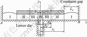
Fig. 1 Sketch of local loading process of T-shaped components
In order to study the local loading process of T-shaped components by using SM, some key assumptions and treatments have been made according to basic assumptions of classical slab method and isothermal local loading forming characteristics of large-scale complex components [7, 9, 12]: 1) the die is considered a rigid body, and the billet a rigid-plastic material; 2) the plastic deformation is by plane strain, and the volume is invariable in the process; 3) the change of temperature is neglected, and flow stress is considered constant in the deformation region; 4) the planes perpendicular to the metal flow direction define principal plane, and the principal stresses do not vary on these planes; 5) the shear friction model is employed to describe the friction at die-billet interface; 6) the shear surface in neighborhood of cavity is simplified as a vertical line. And according to local loading experiment with lead as experimental material, two simplified deformation patterns are established in the study [9]. Deformation pattern 1 is of shearing deformation, in which the metal of web in loading area flows outward. Deformation pattern 2 (Fig. 1) is of upsetting-extruding deformation, in which the metal of web in loading area has two flowing directions: 1) flowing towards lateral portion (region II), and 2) flowing into rib cavity (region III). In deformation pattern 1, the region of IV-II interface is neutral layer; and in deformation pattern 2, the region of II-III interface is neutral layer. The position of neutral layer is expressed as xk.
If the fillet radius has to be included in the model, the region IV can be described as shown in Fig. 2. The unit pressure in x axial direction at x=xb is expressed as q, and the unit pressure in y axial direction at y=0 is expressed as p.
2.2 Description of fillet zone
In order to conveniently analyze the influence of fillet radius on local loading process of T-shaped components, the fillet zone at the base of rib is discretized into elements as shown in Fig. 3. The arc of fillet radius is divided into N equal-length arcs, of which radius angle is ��/2N, and then the line linking two ends of the divided arc is adopted instead of the divided arc.
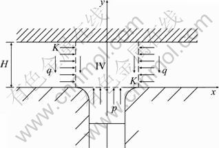
Fig. 2 Sketch of region IV with considering fillet radius
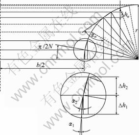
Fig. 3 Discretized elements in fillet zone
According to the geometrical relationship shown in Fig. 3, ��1-��N, ?h1-hN can be expressed as
 (1)
(1)
2.3 Slab method analysis in discretized elements
The fillet zone is discretized into N elements, and the line is adopted instead of arc in each element, as shown in Fig. 4(a).
The boundary condition in discretized element is
![]() (2)
(2)
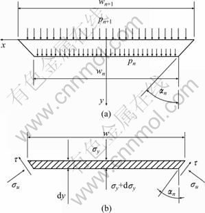
Fig. 4 Stress sketch in the nth discretized element: (a) Force and coordinate; (b) Stress state of small element
The SM analysis is carried out in each element, and a small slab element that is taken from the n-th discretized element is shown in Fig. 4(b).
The width is expressed as
![]() ,
, ![]() (3)
(3)
2.3.1 First analysis in discretized elements (1st ADEs)
A classical rib extrusion model [6] which includes only rib but does not take into consideration fillet radius can be used to analyze discretized elements. BO?R et al [7] used this approach to determine the height of forged rib based on knowing the pressure, i.e., p in the present study, on the entry section of rib cavity, and then analyzed the influence of fillet radius on the height of forged rib.
In the present study, the stress distribution, ��y, in discretized elements is expressed as
![]()
![]() (4)
(4)
where K is the shear yield stress and m is shear friction factor.
For y=0, it is
![]()
![]() (5)
(5)
2.3.2 Second analysis in discretized elements(2nd ADEs)
Another classical slab method model which is used in drawing process by GONZ?LEZ ROJAS et al [13] is that the shear stress is negligible and the stress ��u produced by the die is approximately expressed as
![]() (6)
(6)
By substituting Eqs. (3) and (6) into force equilibrium equation in y axial direction and neglecting second order terms, the following expression can be obtained:
![]() (7)
(7)
By direct integration of Eq. (7), the stress distribution, ��y, in discretized elements, is expressed as
![]() (8)
(8)
Considering the boundary condition Eq. (2), the following expression is obtained:
![]() (9)
(9)
Then, for y=0, it is
![]()
![]() (10)
(10)
2.3.3 Third analysis in discretized elements (3rd ADEs)
With the increasing in angle ��, the discrepancy between Eq. (6) and the fact becomes larger and larger. If the angle �� is close to ��/2, stress ��u can be approximately expressed as ��u=��y. So it is necessary to improve Eq. (6), and Eq. (11) is employed to describe the relationship between ��u and ��y.
![]() (11)
(11)
In the same way (deducing in Section 2.3.2), ��y in discretized elements is expressed as
![]()
![]() (12)
(12)
For y=0, it is
![]()
![]() (13)
(13)
2.4 Synthesizing discretized elements
The fillet zone is discretized into N elements, and the SM analysis is carried out in each element which is filled. If the rib height (h) in local loading process is known, then the pressure p can be solved, and the description of solution algorithm is given: 1) if h��r then
![]() , if h>r then i=2; 2) pi, pi+1, ��,
, if h>r then i=2; 2) pi, pi+1, ��,
pN+1 are obtained by an iteration; and 3) p=PN+1. According to Eqs. (5), (10) and (13), the PN+1 can be expressed as
![]() (14)
(14)
There are two cavity filling cases in consideration of the metal filled in fillet zone: 1) h��r, as shown in Fig. 5(a); 2) h>r, as shown in Fig. 5(b).
Fig. 5 Sketch of cavity fill: (a) h��r; (b) h>r
In different cavity filling cases, the boundary condition, pi-1, is expressed as
 (15)
(15)
where p�� can be obtained according to different conditions of draft angle. If the draft angle is not considered in the model or the draft angle is zero, then p�� is approximately expressed as Eq. (16) with neglecting the friction between the body of rib and the vertical wall of cavity:
p��=0 (16)
If the draft angle is included in the model, i.e., �á�0, p�� is approximately expressed as Eq. (17) according to the SM analysis in Section 2.3.
![]() (17)
(17)
Thus, p can be expressed as
![]() (18)
(18)
3 Mathematical model
3.1 Stress distribution in loading area
Based on the simplified deformation pattern, the expressions of the stress distributions were established [9]. If the fillet radius and draft angle are included in the model, the expressions of the stress distributions can be written as
![]() (19)
(19)
![]() (20)
(20)
![]() (21)
(21)
![]() (22)
(22)
where H is the thickness of web in loading area; b is the rib width (rib entrance); r is the fillet radius between rib and web; xl=l/2, xb=b/2+r; l is the width of punch.
If the region III appear in loading area (the deformation pattern is pattern 2), then Eq. (23) should be satisfied. And if Eq. (23) is not satisfied, then the deformation pattern is pattern 1.
![]() (23)
(23)
whether or not considering the fillet radius would affect the simplification and analysis of region IV, especially the pressure p at region of IV-V interface. And then it affects the values of stresses (Eqs. (19), (20) and (22)) and the transition condition (Eq. (23)) of deformation patterns.
3.2 Neutral layer
In deformation pattern 1, there is xk=xb. In deformation pattern 2, the position of neutral layer can be determined according to the condition that ��y of region II is equal to ��y of region III at the neutral layer. Thus the position of neutral layer which takes into consideration the fillet radius and draft angle can be expressed as
 (24)
(24)
3.3 Rib height
In time increment dt, suppose the position of neutral layer is invariable, the thickness of web in loading area decreases dH (i.e. reduction amount, ds), and the rib height increases dh, as shown in Fig. 6.
Fig. 6 Deforming sketch of center region: (a) h��r; (b) h>r
By taking the initial thickness of billet as H0, the relationship between thickness of web in loading area and reduction amount (s) in loading process can be expressed as
H=H0-s (25)
In the case of h��r (Fig. 6(a)), there is ![]() . According to volume constancy principle, the following expression can be deduced:
. According to volume constancy principle, the following expression can be deduced:
![]() (26)
(26)
where wi=b+2r(1-sin��h), wi-?i=b+2r(1-sin��h+dh); wi and wi-1 in Eq. (26) are not to be confused with those in Eq. (15) and the algorithm for solving p in Section 2.4, of which values are different.
Therefore dh can be solved from Eq. (26).
![]() (27)
(27)
When![]() , the zone below
, the zone below
the fillet zone can be filled. In this case, Eq. (27) should be improved in which draft angle is included. Thus, the solution (in the case of h��r) of dh can be expressed as
![]() (28)
(28)
In the case of h>r (Fig. 6(b)), the following expression can be obtained according to volume constancy principle:
![]() (29)
(29)
Neglecting second order terms, dh can be expressed as
![]() (30)
(30)
However, l is much larger than b in actual practice, and the large dh may be caused by small ds. If second order terms are neglected, the large error is prone to occurrence. The solution of dh has to be improved. The algorithm is shown as follows (�� is a small positive number):
Let![]() ,
,![]() .
.
For i=1, 2, ��, M implement:
1) If![]() then stop, else go to 2);
then stop, else go to 2);
2)![]()
If ��=0, the solution of above procedure is dh=2xkdH/b, which implies that the procedure will stop when i=1. The solution can be expressed as
![]() (31)
(31)
3.4 Loading force
Based on the results in Ref. [9] and above analysis, the loading force (F) per unit length which takes into consideration the fillet radius and draft angle can be expressed as
 (32)
(32)
3.5 Program development and its verification
In order to distinguish between the new SM model (including draft angle and fillet radius) and the SM model in the study [9], the SM model in the study [9] is expressed as Simplified SM model, and the new SM models established based on 1st ADEs, 2nd ADEs and 3rd ADEs are expressed as Improved SM model 1, 2 and 3 respectively.
The new mathematical model established in the present study can describe the relationship between the geometric parameters of cavity such as fillet radius and draft angle and the forming results. However, the model is complicated and difficult to be solved by analytic solution. It can be seen from Eqs. (19), (20), (22)-(24) and (26)-(32) that the results are inter-coupled with forming parameters and are an implicit function of unknown h. Thus, the numerical method is used to implement quantitative calculation and analysis.
Based on the above work, the program for solving the new SM model is developed, and the flowchart is shown in Fig. 7. In order to make cavity fill steady and reduce possibility of defects such as under-filling, folding, flow lines disturbance, it is better to make cavity be filled under deformation pattern 2. If shearing deformation which is one of output results is true (i.e. non-zero), then it is necessary to increase width of loading area or decrease thickness of billet for making xk>xb in the process.
Fig. 7 Flowchart of calculation-program
Neglecting fillet radius and draft angle, the analytical result of rib height can be obtained from Simplified SM model. Let r=0 and ��=0, the computational conditions are retrogressed to the conditions of Simplified SM model, and then the numerical results should equal the analytical results. So, the comparison of rib height between analytic and numerical solutions is carried out in order to verify the reliability of the calculation-program. The analytical and numerical results of rib height are listed in Table 1, where l=60 mm, b=8 mm, m=0.3 mm. It can be seen from Table 1 that the numerical results show a good agreement with the analytical results. This indicates that the developed calculation-program is reliable.
Table 1 Comparison of rib height between analytic (hana) and numerical (hnum) solutions
4 Results and discussion
4.1 Verification of model
4.1.1 Experiment and finite element simulation
In order to validate the prediction of the improved SM model in the present study, experiment and finite element simulation were carried out. Lead can be selected as modeling material for titanium alloy hot forming, as declared by DUTTA and RAO [14]. ZHANG et al [9] also presented that the distribution of strain in the local loading process (at room-temperature) using lead is similar to the distribution of strain in the local loading process (at elevated temperature) using Ti-6Al-4V alloy. In order to simplify the experiment, reduce the cost and save the time, the lead is selected as formed material. The dies used in experiment consist of punches and split segment lower die.
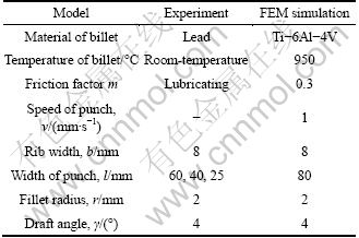
In the numerical simulation by means of finite element method (FEM), the commercial software DEFORM is used. The FE model of local loading process of T-shaped component is built based on plane strain. In the FE model, the metal yields based on the Mises yielding criteria, and the shear friction model is employed. The formed material is Ti-6Al-4V alloy, of which material properties come from the material library of DEFORM. The main parameters are summarized in Table 2.
Table 2 Main parameters in experiment and FEM simulation
4.1.2 Comparison with experimental results
Figure 8 shows the analytical, numerical and experimental results of rib height under different local loading conditions. The analytical results are based on Simplified SM model in the study [9], and the numerical results are based on Improved SM models 1, 2 and 3, respectively in the present study. It can be seen from Fig. 8 that the results based on Improved SM model 3 show a good agreement with the analytical and experimental results, and the results based on Improved SM model 3 are closer to the experimental results. However, the discrepancies between the results based on Improved SM models 1 and 2 and the experimental results are larger. With the decrease in width of punch, the results respectively based on Improved SM models 1 and 2 gradually close, and the results are equal when l/b<5. The reasons are: 1) based on Improved SM models 1 and 2, the calculation values of Eq. (23) are almost the same, which estimates that the deformation pattern in the whole process is pattern 1 (i.e. shearing deformation) when l/b<5; and 2) in shear deformation, the predicted results are determined by reduction amount, fillet radius and draft angle, which have no relationship with local loading condition l. The second reason is also contributive to the fact that the deformation behavior in deformation pattern 1 is difficult to be described by the SM model.
When l=40 mm, the deformation pattern is almost the pattern 1 in the whole local loading process, which is estimated by Improved SM models 1 and 2; but the deformation pattern is the pattern 1 at initial stage and the deformation pattern is the pattern 2 at late stage, which is estimated by Improved SM model 3 and Simplified SM model. Figure 9 shows the meshes in cross-section when l=40 mm, and it can be seen from the meshes that there is a notable neutral layer in web region. This indicates that Improved SM models 1 and 2 are not suitable to analyze the local loading process of T-shape components but Improved SM model 3 can be used to analyze the process.
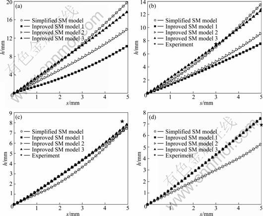
Fig. 8 Comparison of experimental, analytical and numerical results: (a) l=80 mm; (b) l=60 mm; (c) l=40 mm; (d) l=25 mm

Fig. 9 Meshes of cross-section of T-shaped component under l=40 mm
The research of finite element method and experiment indicate that [9]: with the decrease in l/b, more and more cavity filling behaviors are performed under the deformation pattern 1 (shearing deformation); the SM model is difficult to describe the shearing deformation accurately; the analytical results can be as reliable as the FEM results when l/b>5; the larger the l/b, the smaller the error. When l=25 mm, the shearing deformation occurs throughout forming process dominantly which is also estimated by Improved SM model 3, and then the results based on Improved SM models 1, 2 and 3 are the same (see Fig. 8(d)). Even if the width of punch is less than 25 mm, the predicted results are also the same in Fig. 8(d) because of the assumptions and simplifications in Section 2. Thus Improved SM model 3 also difficultly describes the deformation behavior when l/b<5, although the relative error between predicted and experimental results in Fig. 8(d) is less than 10%. The error between numerical (based on Improved SM model 3) and experimental results is expressed as en (en=|(hn-hexp)/hexp|��100%), and the error between analytical (based on Simplified SM model) and experiment results is expressed as ea (ea=|(ha-hexp)/hexp|��100%). It can also be seen from Fig. 8 that: when l=40 mm, en reduces 3% comparing ea; when l=60 mm, en reduces 3% comparing ea at s=3 mm, and en reduces 7% comparing ea after forming where the error en is less than 1%.
4.1.3 Comparison with FEM results
The yield stress used in the slab method model for calculating loading force is considered a constant in local loading process. So, the SM model is difficult to predict loading force accurately. ZHANG et al [9] presented that if the flow stress Y at mean effective strain rate (for a material sensitive to strain rate, such as titanium alloy) of different forming stages is adopted instead of the constant yield stress ��s, the error between SM and FEM will be reduced. However, the SM modeling is more complicated by using this way, and error of loading force is also larger than error of rib height. Thus, to predict the loading force accurately, FEM is a well approach.
Shearing yield strength K is a factor which can directly reflect the influence of material behavior on SM model. It can be seen from Sections 2.4, 3.2, 3.3 and 3.4 that there is no relationship between the shearing yield strength and the neutral layer and rib height, and the value of shearing yield strength only affects the value of loading force F. To some extent, the nondimensional parameter F/K can reflect the changing tendency of loading force. It can be seen from Fig. 10(a) that changing tendency predicted by Improved SM model 3 is closer to the true station than that predicted by Simplified SM model. At the late stage of local loading process, the material between the punch and the vertical wall warps to go from horizontal surface AB in FEM simulation, so the loading force becomes smooth at the late stage.
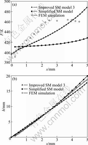
Fig. 10 Comparison between FEM and SM results: (a) Loading force; (b) Rib height
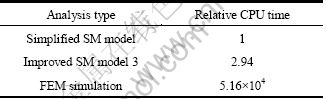
Figure 10(b) indicates that the rib heights predicted by SM show a good agreement with FEM results. In the process of rib-web components isothermal forming under high temperature and low strain rate, the metal flow and rib height predicted by SM may be accepted to provide an initial range of the processing parameters and boundary condition. Although the improved SM model involves iterations, the consuming CPU time is also much less than that by FEM consuming. For example, the rib height in the local loading process (l=80 mm) of T-shaped component is solved by Simplified SM model, Improved SM model 3 and FEM. The consuming CPU time of the improved SM model is also less than 0.1 s, which is about three times as much as the CPU time of the simplified SM model. And the consuming CPU time of the improved SM model is also much less than that by FEM consuming, as shown in Table 3.
Table 3 Comparison of CPU time
In the initial analysis of local loading process of large-scale rib-web components, it may be concerned chiefly with the metal distribution and cavity fill when the laws based on eigenstructure such as T-shaped components are used to analyze the local loading process of large-scale components. Calculation and theoretical analysis are carried out for specific parameters, and then the initial geometrical parameter of billet, division of die, simulation parameter and boundary condition would be obtained. The reasonable parameter ranges can be determined quickly by using SM. The detailed parameter optimization, process optimization and process control are carried out by means of three-dimensional finite element simulation.
4.2 Influences of fillet radius and draft angle
Using the Improved SM model 3, the influences of fillet radius and draft angle on the local loading process of T-shape component were studied. According to the precision forging process of rib-web components and considering the extended parameters range, the values of fillet radius and draft angle are r/b=0.25-1.25 and ��=1��-5��.
The rib height and loading force under different fillet radii are shown in Fig. 11. With the increasing in fillet radius, the volume of fillet zone increases. Thus, at initial forming stage, the larger the fillet radius, the slower the heightening velocity of rib; and force decreases obviously when fillet radius increases. But the cavity section becomes narrow after half of fillet zone is filled, and then the heightening velocity becomes high and the force increases notably. Finally, there are notable differences in rib height (he, i.e. the maximum height) after forming and there are a few differences in maximum loading force. For different draft angles, the tendency of influence of fillet radius is the same. In local loading process, he increases when fillet radius increases; but in extrusion forging process, the boss height after forming decreases when fillet radius increases [8].
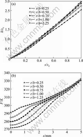
Fig. 11 Rib heights and loading forces in process under different r/b: (a) Rib height; (a) Loading force
With the increasing in fillet radius, he increases notably when r/b<0.75, and there are a few changes in he when r/b>0.75. L? [11] summarized that not only the cavity fill is difficultly but also some defects such as folding and cutting metal wool are prone to occurrence for some components under smaller fillet radius. Of course, the larger fillet radius will increase the machining allowance and material loss. Thus, the value of fillet radius of rib-web forging may be chosen from r/b=0.25-0.75 in consideration of rib height after forming.
The influences of draft angle on rib height and loading force are shown in Fig. 12. It can be seen from Fig. 12 that there are a few influences on rib height and there are differences in loading force. With the increasing in draft angle, the loading force also increases which is similar to the analysis in conventional forging. However, its relative value is small. In Fig. 12, the maximum loading force only increases by 2.83% from ��=1�� to ��=5��. And this law is the same for different fillet radii.
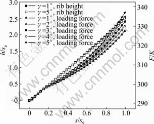
Fig. 12 Rib heights and loading forces in processes under different draft angles
Figure 13 shows the rib height under different fillet radii and draft angles. Under different fillet radii, the influence of draft angle on he represents two cases as the following and there is a critical fillet radius rk: 1) when r<>k, he decreases with increasing in draft angle; 2) when r>rk, he increases with increasing in draft angle. The former is similar to the influence of draft angle on he in the whole forging of thin rib [7]; and the later is similar to the influence of draft angle on boss height after extrusion forging [8]. It can be seen from Fig. 13 that the critical fillet radius decreases when the l/b increases. Of course, the relative value of increasing or decreasing is small. In Fig. 13, its relative value (|(he|��=5��-he|��=1��)/ he|��=1��|��100%) is less than 2.5% if the other parameters are not varied. The influence of draft angle on the whole forged rib height under hot forming condition is also small [7].
Just as PARK and HWANG [15] declared in his publication that the rib-web type aerospace and aircraft components in general have small draft angle even with zero draft angle. For large-scale rib-web components, the changes in dimensions caused by draft are small compared with the dimensions of the forging. It brings difficultly to describe geometry and to mesh workpiece in 3D-FE modeling and it adds the CPU time and storage capacity. Fortunately, according to the above analysis, there are a few influences of draft angle on forming results. Thus the draft angle can be neglected in 3D-FE modeling to simplify the FE model.
One large-scale titanium alloy bulkhead (greater than 1.2 m in length, about 1 m in width) is formed by using isothermal local loading forming technique. In the process, the formed material is Ti-6Al-2Zr-1Mo-1V, the temperature in holding-furnace is 970 ��C, the speed of upper die is 0.2 mm/s, and the draft angle of the forging is 1.5��. The local loading forming process is realized in ordinary isothermal forging press, and it has two local loading steps: the first local loading step, the upper 2 is higher than the upper 1, thus the load is applied to billet by upper die 1; and the second local loading step, the upper 1 and the upper 2 are at the same height, but the load is applied to billet by upper die 2 due to local forming in the first step.
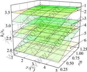
Fig. 13 Rib heights after local loading under different forming conditions: 1��l/b=9, Improved SM model 3; 2��l/b=9, simplified SM model; 3��l/b=7.5, Improved SM model 3; 4��l/b=7.5, Simplified SM model; 5��l/b=6, improved SM model 3; 6��l/b=6, Simplified SM model
The finite element analysis (FEA) of the isothermal local loading process of titanium alloy bulkhead is performed. Two simulations (FEA-I and II) are carried out, which differ in terms of the modeling. In 3D-FE modeling, draft angle (��=1.5��) is considered for FEA-I, and draft angle is not considered for FEA-II.
The changes of loading force in the second local loading step are shown in Fig. 14. It can also be seen from Fig. 14 that the changing tendency and the value in both simulations are almost the same. Of course, the value in FEA-I is closer to the value in experiments. The relative error of load between FEA-I and experiment is less than about 10%, and relative error between FEA-II and experiment is less than about 15%. All of the above indicate that draft angle has a few influences on the local loading process, and these also indicate farther that the conclusions obtained by SM model are credible.
The rib heights after forming under different fillet radii and draft angles are compared with the analytical results in the study [9], as shown in Fig. 13. The error (e=|(hn-ha)/ha|��100%) between numerical and analytical results decreases when l/b increases. In Fig. 13, the value of the error is generally less than 10% and the maximum is about 20% in the range of r/b=0.25-0.75. Simplified SM model which does not include fillet radius and draft angle can be used to determinate the initial forming parameters such as thickness of billet and division of die at the first optimization stage for large-scale rib-web components local loading.

Fig. 14 Loading force in second local loading step
5 Conclusions
1) Three SM analyses such as 1st ADEs, 2nd ADEs and 3rd ADEs are used to analyze the fillet zone at the base of rib. Based on the analyses of fillet zone, the fillet radius and draft angle are taken into SM analysis of the local loading process of T-shaped components, and the new mathematical models are established, such Improved SM models 1, 2 and 3 based on 1st ADEs, 2nd ADEs and 3rd ADEs, respectively. The experimental results indicate that Improved SM model 3 is suitable to analyze the local loading process of T-shape components. When l/b>5, Improved SM model 3 can describe the deformation behavior, and the predicted results are closer to the experimental and FEM results compared with the predicted results by Simplified SM model.
2) Improved SM model 3 is used to study the influences of fillet radius and draft angle on the local loading process of T-shape component. The results show that there are a few influences of draft angle on rib height and loading force; the influence of fillet radius on the rib height after forming, he, is notable, but the influence of fillet radius on the maximum loading force is small.
3) There are a few changes in he when r/b>0.75, and thus the value of fillet radius of rib-web forging may be chosen as r/b=0.25-0.75 in the interest of rib height. The draft angle can be neglected in 3D-FE modeling of the local loading process of rib-web type aerospace and aircraft components.
References
[1] YANG He, LI Luo-xing, WANG Qu-dong, GUO Liang-gang. Research on the development of advanced forming for lightweight alloy materials area [J]. Journal of Mechanical Engineering, 2010, 46(12): 31-42. (in Chinese)
[2] SHEN G, FURRER D. Manufacturing of aerospace forging [J]. Journal of Materials Processing Technology, 2000, 98: 189-195.
[3] YANG He, SUN Zhi-chao, ZHAN Mei, GUO Liang-gang, LIU Yu-li, LI Hong-wei, LI Heng, WU Yue-jiang. Advances in control of unequal deformation by locally loading and theories related to precision plastic forming [J]. Journal of Plasticity Engineering, 2008, 15(2): 6-14. (in Chinese)
[4] SHAN D B, XU W C, LU Y, SI C H. Research on local loading method for an aluminium-alloy hatch with ribs and thin webs [J]. Journal of Materials Processing Technology, 2007, 187-188: 480-485.
[5] SUN Z C, YANG H. Mechanism of unequal deformation during large-scale complex integral component isothermal local loading forming [J]. Steel Research International, 2008, 79(S1): 601-608.
[6] ALTAN T, et al. Modern forging: Equipment, materials and process [M]. LU Suo, trans. Beijing: Defence Industrial Press, 1982. (in Chinese).
[7] BO?R C R, REBELO N, RYDSTAD H, SCHR?DER G. Process modelling of metal forming and thermomenchanical treatment [M]. Berlin: Springer-Verlag, 1986.
[8] WU C Y, HSU Y C. The influence of die shape on the flow deformation of extrusion forging [J]. Journal of Materials Processing Technology, 2002, 124: 67-76.
[9] ZHANG D W, YANG H, SUN Z C. Analysis of local loading forming for titanium-alloy T-shaped components using slab method [J]. Journal of Materials Processing Technology, 2010, 210: 258-266.
[10] WU Yue-jiang, YANG He, SUN Zhi-chao, FAN Xiao-guang. Simulation on influence of local loading conditions on material flow during rib-web components forming [J]. China Mechanical. Engineering, 2006, 17(Sl): 12-15 (in Chinese).
[11] L? Yan. Technology of precision plastic bulk forming [M]. Beijing: Defence Industrial Press, 2003. (in Chinese).
[12] ALTAN, T, OH S I, GEGEL H L. Metal forming: Fundamentals and application [M]. Metal Park, OH: American Society for Metals, 1983.
[13] GONZ?LEZ ROJAS H A, CALVET J V, BUBNOVICH V I. A new analytical solution for prediction of forward tension in the drawing process [J]. Journal of Materials Processing Technology, 2008, 198: 93-98.
[14] DUTTA A, RAO A V. Simulation of isothermal forging of compressor disc by combined numerical and physical modeling techniques [J]. Journal of Materials Processing Technology, 1997, 72: 392-395.
[15] PARK J J, HWANG H S. Preform design for precision forging of an asymmetric rib-web type component [J]. Journal of Materials Processing Technology, 2007, 187-188: 595-599.
Բ�ǰ뾶����ģб�ȶ��ѺϽ�T����
�ֲ����ع��̵�Ӱ��
�Ŵ�ΰ, �� ��, ��־��, ������
������ҵ��ѧ ����ѧԺ�����̼��������ص�ʵ���ң����� 710072
ժ��Ҫ��Ϊ���о����β�����T�����ֲ����ع��̵�Ӱ�죬Ӧ����Ӧ���������˳�ֿ���Բ�ǰ뾶����ģб�ȵ���ģ�͡�ʵ�����ֵģ������֤��������ѧģ�͵Ľ�����ӽ���ʵ�����ֵģ��ֵ����ģб�ȵ�Ӱ����Ժ��ԣ�Բ�ǰ뾶��Ӱ���������ر�����Բ�ǰ뾶�ͽ���ı���С��0.75������¸�Ϊ������
�ؼ��ʣ�Բ�ǰ뾶����ģб�ȣ�T�������ֲ����أ���Ӧ����
(Edited by LI Xiang-qun)
Foundation item: Project (50935007) supported by the National Natural Science Foundation for Key Program of China; Project (2010CB731701) supported by the National Basic Research Program of China; Project (50905145) supported by the National Natural Science Foundation of China
Corresponding author: YANG He; Tel/Fax: +86-29-88495632; E-mail: yanghe@nwpu.edu.cn; zhangdawei2000@yahoo.com.cn
DOI: 10.1016/S1003-6326(11)61112-6
Abstract: In order to study influences of geometric parameters on the T-shaped components local loading process, a new mathematical model considering the fillet radius and draft angle was established by using the slab method. The results obtained by the mathematical model agree with the data form experiment and numerical simulation, and the results are closer to the experimental and simulation results. The influence of draft angle may be neglected under the forming conditions used. The influence of fillet radius is notable, especially in the case that the ratio of fillet radius to rib width is less than 0.75.
