

Collapse behavior evaluation of hybrid thin-walled member by stacking condition
Kil-Sung LEE1, Hyeon-Kyeong SEO2, Yong-June YANG2,
Woo-Chae HWANG2, Kwang-Hee IM3, In-Young YANG4
1. R&D Center, Dacc LTD., 948-13 Dunsan-ri, Bongdong-eup, Wanju-gun, Jeonbuk 565-902, Korea;
2. Departments of Advanced Parts and Materials Engineering, Graduate School, Chosun University,
375 Seosuk-dong, Dong-gu, Gwangju 501-759, Korea;
3. Department of Automotive Engineering, Woosuk University, 490 Hujung-ri, Samrae-up,
Wanju-kun, Chonbuk 567-701, Korea;
4. Departments of Mechanical Design Engineering, Chosun University, 375 Seosuk-dong,
Dong-gu, Gwangju 501-759, Korea
Received 21 April 2010; accepted 10 September 2010
Abstract:
The recent trend of vehicle design aims at crash safety and environmentally-friendly aspect. For the crash safety aspect, the energy absorbing members should absorb collision energy sufficiently but for the environmentally-friendly aspect, the vehicle structure must be light weight in order to improve the fuel efficiency and reduce the tail gas emission. Therefore, the light weight of vehicle must be achieved in a securing safety status of crash. An aluminum or carbon fiber reinforced plastics (CFRP) is representative one of the light-weight materials. Based on the respective collapse behavior of aluminum and CFRP member, the collapse behavior of hybrid thin-walled member was evaluated. The hybrid members were manufactured by wrapping CFRP prepreg sheets outside the aluminum hollow members in the autoclave. Because the CFRP is an anisotropic material whose mechanical properties, such as strength and elasticity, change with its stacking condition, the effects of the stacking condition on the collapse behavior evaluation of the hybrid thin-walled member were tested. The collapse mode and energy absorption capability of the hybrid thin-walled member were analyzed with the change of the fiber orientation angle and interface number.
Key words:
collapse behavior; aluminum and CFRP; hybrid thin-walled member; stacking condition;
1 Introduction
The car parts as the configuration are made up of various materials. These materials due to consumers and the environment continue to change and have been developed. According to these demands, the automotive materials are changed. As well as the high-strength materials, light-weight metal and plastic, environmentally-friendly materials and nano-materials have been developed. The light-weight materials, such as the aluminum, magnesium alloy, non-ferrous metal and glass fiber reinforced plastics (GFRP) and carbon fiber reinforced plastics (CFRP) are used. The research for these advanced applications and the extend use is predicted. When the hybrid thin-walled members, such as aluminum and carbon fiber reinforced plastics (CFRP) members, which are representative light-weight materials, are subjected to axial loading, the aluminum member absorbs energy through stable plastic deformation [1-5]. The CFRP member has higher specific strength and stiffness than the aluminum member, but it absorbs energy by unstable brittleness fracturing [6-8].
The hybrid thin-walled members were manufactured using aluminum and carbon fiber reinforced plastics (CFRP) which are representative light-weight materials. The disadvantages of aluminum and CFRP members were considered to be mutually complimentary while the advantages of each member were combined to exhibit the collapse characteristics of effective structural members. The impact axial collapse tests were carried out for the hybrid thin-walled members, which comprised an aluminum member externally reinforced by stacking CFRP. In particular, among the design variables of the anisotropic CFRP, the axial collapse characteristics have been examined according to the changes of orientation angle. The CFRP is an anisotropic material whose mechanical properties, such as strength and elasticity change with its stacking condition. The collapse mode and energy absorption capability of hybrid thin-walled member were analyzed with change of the fiber orientation of CFRP and interface number.
2 Experimental
2.1 Specimen
The circular and square members, which are the basic structure as side members of automobile, were used as specimens. The aluminum circular and square members were 6063-T5 with thickness of 1.0 mm. The circular member has outside diameter of 38 mm and length of one side of square member of 30 mm. The hybrid thin-walled member was molded using autoclave by laminating the exteriors of aluminum circular and square member with unidirectional carbon fiber/epoxy resin prepreg sheet (CU125NS) produced by HANKUK Fiber Co. In addition, in order to examine the influence of CFRP interface number of composite structural member on the characteristics of energy absorption, it was stacked in 2, 3, 4, 6 and 7 interface with outside angle of 90��. And in order to investigate the effect of the fiber orientation angles of CFRP, the orientation angle of the hybrid thin-walled members were stacked to [+15��/-15��]4, [+45��/-45��]4, [90��]8, [0��/90��]4 and [90��/0��]4 of 8 plies, respectively.
Fig.1 shows the schematic diagram of experimental specimen shape. A molding of specimen was manufactured in the method of vacuum bag molding using autoclave. It was manufactured by a heater located inside the circumference of chamber by setting hardening point temperature of 130 ��C and hardening time of 90 min and also it was manufactured by providing about
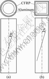
Fig.1 Schematic diagram of specimens: (a) Circular member; (b) Square member
300 kPa compression from outside of vacuum bag with a compressor after vacuuming inside of vacuum bag up to 0.1 Pa by vacuum pump during molding. Fig.2 indicates the molding cycle during manufacturing specimens.
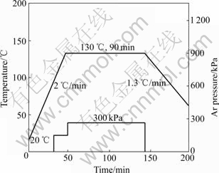
Fig.2 Curing cycle of CFRP specimens
All specimens were cut to pieces with a length of 120 mm using a diamond cutter in order to be not affected by the end effects and observe repetitive and agreeable collapse mode with the theoretical folding width of 22 mm [9].
2.2 Impact collapse test
The axial impact collapse testing device using compressed air is shown in Fig.3. Fig.4 shows the schematic diagram of measurement system. The cross head, which is accelerated by the compressed air and guided by four guide bars, dropped and collided with the specimen on the load cell. In the tests, the impact loads were obtained by converting the electrical resistance variations on the strain gage into loads. In collision, the resistance variations on the strain gage going through the shield line and bridge box were fed into a dynamic strain amplifier which converted the signal into voltage variations. The specimen deformation was measured by an optical deformation system (ZIMMER 100F) which captured the movement of the target on the cross head. The impact velocity was measured just before the cross head collided with the specimen by determining the time taken for cross head to pass two laser beams.
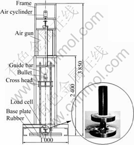
Fig.3 Impact testing device set up (mm)
A load��displacement curve for the collapse history was obtained by eliminating the time axis from the measured time��load and time��displacement curves. The absorbed energy is equal to the area below the load�� displacement curves and is calculated by integrating the load with respect to the displacement as Eq. (1).
![]() (1)
(1)
The specimens did not collapse equally in length. It was assumed that the specimens would collapse as much as the total length of 120 mm in order to analyze the total absorbed energy quantitatively [10]. The total absorbed energy (Et) is given as below Eq.(2):
![]() (2)
(2)
The value of the impact energy (EI) is similar to that given by Eq.(3): 1 136.64 J at 7.54 m/s, 833.07 J at 6.45 m/s and 465.96 J at 4.82 m/s.
![]() (3)
(3)
where m is the mass of the cross head (40 km) and v is the impact collapse velocity.
The impact collapse velocities were selected as follows: the impact velocities of hybrid members whose fiber orientation angles of CFRP are 45��, 90��, 0��/90�� and 90��/0�� were 7.584 m/s (circular members) and 6.45 m/s (square members). And those of hybrid circular and square members whose fiber orientation angle of CFRP is 15�� were 4.82 m/s. The impact velocities were selected due to the energy absorption capability of hybrid members during the impact collapse. The higher velocity could not be selected owing to the limits of energy absorption capability of the hybrid members.
3 Results and discussion
3.1 Collapse mode
The aluminum members collapsed stably with axial symmetrical mode, non-axial symmetrical mode, and compound mode comprising a mixture of axial symmetrical and non-axial symmetrical modes [11-15]. However, the CFRP member collapsed in transverse shearing, lamina bending and local buckling according to the shape of the member and the mechanical properties of the fiber and matrix [16-18]. Three unique collapse modes, as defined by Farley and Jones [18-21], were exhibited by continuous fiber-reinforced composite member (transverse shearing, laminar bending and local buckling). Most members fabricated from brittle-fiber reinforcements collapse in a combination of transverse shearing and lamina bending modes. This combined mode is referred to be the brittle fracturing crushing.
In this study, the hybrid members collapsed in a combination of aluminum collapse modes and CFRP collapse modes. These collapse modes were determined mainly by the fiber orientation angle. Fig.5 shows the typical collapse modes of hybrid circular and square members with change of the fiber orientation angle.
When the fiber orientation angle is stacked similarly to the axial direction ([+15��/-15��]4), the fibers of outer CFRP member are splayed and split at interface of the CFRP member and aluminum member. Therefore, the CFRP member cannot be held between the folds of the aluminum member and is separated from the aluminum member. The interaction effect by combination of two members is not shown. This member absorbed energy by progressive deformation in the inner aluminum member and laminar bending in the outer CFRP member. With increasing the fiber orientation angle ([+45��/-45��]4), some of the fibers are held between the folds of the aluminum member by local buckling, and the remaining fibers are broken. This member absorbed energy by progressive deformation of the inner aluminum member and local buckling and fiber breaking of the outer CFRP member. When the orientation angle approaches the direction perpendicular to the axis ([90��]8), in the case of square member, most of fibers of outside CFRP member are inserted into the folding of aluminum members. However, in the case of circular member, most of the fibers are broken without being inserted between the folds of the aluminum member due to the excessively small gap in the folding.
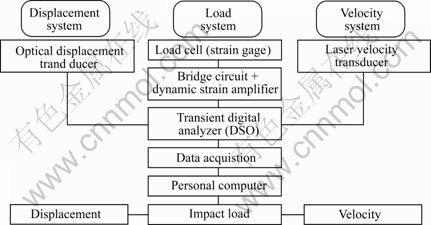
Fig.4 Schematic diagram of measurement system
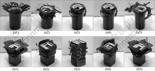
Fig.5 Collapse modes of circular (a) and square (b) members according to fiber orientation angle: (a1) [+15��/-15��]4; (a2) [+45��/-45��]4; (a3) [90��]8; (a4) [0��/90��]4; (a5) [90��/0��]4; (b1) [+15��/-15��]4; (b2) [+45��/-45��]4; (b3) [90��]8; (b4) [0��/90��]4; (b5) [90��/0��]4
In the member with [0��/90��]4 fiber orientation angle, the outer 0�� fibers are splayed to the external by laminar bending, while the inner 90�� fibers are held between the folds of the aluminum member by local buckling. When the fiber orientation angle of the member is [90��/0��]4, the outer 90�� fibers of the member are broken and held between the folds of the aluminum member, while the inner 0�� fibers are splayed to the external of the member.
3.2 Energy absorption capability
Table 1 indicates the average value of the result obtained after conducting impact collapse test in axial direction by changing the fiber orientation angle. Fig.6 shows the impact test results of the total absorbed energy according to fiber orientation angle. Fig.7 shows RT relationship between total absorbed energy and interface number.
As shown in Table 1 and Fig.6, the total absorbed energy of the member with [0��/90��]4 and [90��/0��]4 fiber orientation angle is larger than that of the member with [90��]8 fiber orientation angle, while the member with [0��/90��]4 fiber orientation angle exhibits the highest value.
With increasing the fiber orientation angle of the hybrid member, the fibers are oriented perpendicularly from the axial direction and supported loaded in the form of hoop stress. These fibers interrupt the folding of the inner aluminum member as it approaches collapse, and thereby raises the load and absorbs energy before the hybrid member collapses in a stable manner. At this time, the fibers are broken and inserted between the folds of the aluminum member.
Table 2 indicates the average value obtained after conducting impact collapse test in axial direction by changing interface. In Fig.7, the relation of interface number and total absorbed energy is indicated.
From Table 2 and Fig.7, it is found out that the absorbed energy does not affect significantly the changes of interface number. The reason is that the biggest factor of absorbed energy of CFRP member is the fiber breaking and propagation of crack. The crack can largely be classified into inter-laminar crack, the intra-laminar crack and central crack [21]. Therefore, in the case of CFRP member, it is found out that it is effective for the absorbed energy as the number of frequency of generating cracks between layers according to the increase of interface number increases. However, in the case of the hybrid thin-walled member, the influence of energy absorption capability by interface number does not appear because the energy is absorbed mainly by the fiber breaking and stabled plastic deformation of aluminum not the propagation of crack.
And absorbed energy of circular member is approximately 47% higher than square member. Since the stress is concentrated on their edges when the strength member receives axial load and therefore, it is believed that the circular member has infinite number of corners absorbing more energy than the square member with four corners.
Table 1 Average value of test results of specimens according to fiber orientation angle of CFRP
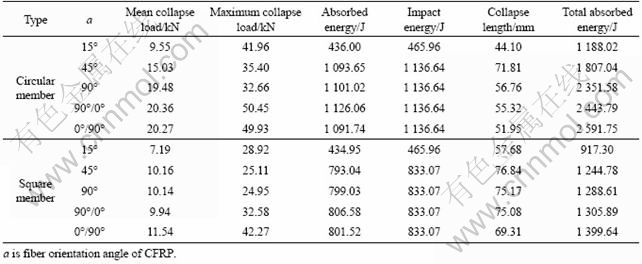
Table 2 Average value of test results of specimens according to interface number
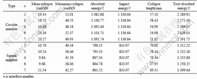
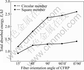
Fig.6 Relationship between total absorbed energy and fiber orientation angle
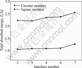
Fig.7 RT Relationship between total absorbed energy and interface number
4 Conclusions
1) The hybrid member is collapsed at high load due to the high specific stiffness and strength of CFRP, and it shows relatively stable collapse mode by complimenting disadvantage of brittle fracture of CFRP member with stable collapse of aluminum member.
2) Both the circular and square members are collapsed as outside CFRP fiber is being inserted into the folding of aluminum member, and the absorbed energy is accomplished mostly by the fiber breaking and also is accomplished by the propagation of cracks partially.
3) The total absorbed energy of the member with fiber orientation angle of [0��/90��]4 and [90��/0��]4 is larger than that of the member with fiber orientation angle of [90��]8, while the member with fiber orientation angle of [90��/0��]4 exhibits the highest value.
4) The influence of energy absorption capability by interface number does not appear, because the energy is absorbed mainly by the fiber breaking and stabled plastic deformation of aluminum not the propagation of crack.
References
[1] KIM S K, IM K H, KIM Y N, PARK J W, YANG I Y, ADACHI T. On the characteristics of energy absorption control in thin-walled members for the use of vehicular structures [J]. Key Engineering Materials, 2003, 233-236: 239-244.
[2] LI S, REID S R. Relationship between the elastic bucking of square tubes and rectangular plates [J]. International Journal of Applied Mechanics, 1990, 57: 969-973.
[3] YAMASHITA M, GOTOH M, SAWAIRI Y. Axial crush of hollow cylindrical structures with various polygonal cross-sections numerical simulation and experiment [J]. Journal of Materials Processing Technology, 2003, 140: 59-64.
[4] SINGACE A A. Axial crushing analysis of tubes deforming in the multi-mode [J]. International Journal of Mechanical Science, 1999, 41: 865-890.
[5] AVALLE M, BELINGARDI G. Experimental evaluation of the strain field history during plastic progressive folding of aluminum circular tubes [J]. International Journal of Mechanical Science, 1997, 39(5): 575-583.
[6] MAMALIS A G, MANOLAKOS D E, IOANNIDIS M B, PAPAPOSTOLOU D P. Crashworthy characteristics of axially statically compressed thin-walled square CFRP composite tubes [J]. Composite Structures, 2004, 63: 347-360.
[7] FARLEY G L, JONES R M. Crushing characteristics of continuous fiber-reinforced composite tubes [J]. Journal of Composite Materials, 1992, 26(1): 37-50.
[8] KIM Y M, HWANG J J, BAEK K Y, CHA C S, YANG I Y. Impact collapse characteristics of CF/Epoxy composite tubes for light-weights [J]. KSME International Journal, 2003, 17(1): 48-56.
[9] MAHMOOD H F, PALUZNY A. Axial collapse of thin wall cylindrical column [J]. Society of Automotive Engineers, 1985, 3: 995-1005.
[10] CHA C S, CHUNG J O, PARK J W, KIM Y N, YANG I Y. Collapse analysis of spot welded thin section members in a vehicle body structure at various impact velocities [J]. KSME International Journal, 2003, 17(4): 501-510.
[11] KIM S K, IM K H, KIM Y N, PARK J W, YANG I Y, ADACHI T. On the characteristics of energy absorption control in thin-walled members for the use of vehicular structures [J]. Key Engineering Materials, 2003, 233-236: 239-244.
[12] LI S, REID S R. Relationship between the elastic bucking of square tubes and rectangular plates [J]. International Journal of Applied Mechanics, 1990, 57: 969-973.
[13] YAMASHITA M, GOTOH M, SAWAIRI Y. Axial crush of hollow cylindrical structures with various polygonal cross-sections numerical simulation and experiment [J]. Journal of Materials Processing Technology, 2003, 140: 59-64.
[14] SINGACE A A. Axial crushing analysis of tubes deforming in the multi-mode [J]. International Journal of Mechanical Science, 1999, 41: 865-890.
[15] AVALLE M, BELINGARDI G. Experimental evaluation of the strain field history during plastic progressive folding of aluminum circular tubes [J]. International Journal of Mechanical Science, 1997, 39(5): 575-583.
[16] MAMALIS A G, MANOLAKOS D E, IOANNIDIS M B, PAPAPOSTOLOU D P. Crashworthy characteristics of axially statically compressed thin-walled square CFRP composite tubes [J]. Composite Structures, 2004, 63: 347-360.
[17] KIM Y N, HWANG J J, BAEK K Y, CHA C S, YANG I Y. Impact collapse characteristics of CF/Epoxy composite tubes for light-weights [J]. KSME International Journal, 2003, 17(1): 48-56.
[18] FARLEY G L, JONES R M. Crushing characteristics of continuous fiber-reinforced composite tubes [J]. Journal of Composite Materials, 1992, 26: 37-50.
[19] FARLEY G L, JONES R M. Analogy for the effect of material and geometrical variables on energy-absorption capability of composite tubes [J]. Journal of Composite Materials, 1992, 26: 78-89.
[20] FARLEY G L, JONES R M. Crushing characteristics of composite tubes with ��near-elliptical�� cross sections [J]. Journal of Composite Materials, 1992, 26: 1741-1751.
[21] FARLEY G L, JONES R M. Prediction of the energy-absorption capability of composite tubes [J]. Journal of Composite Materials, 1992, 26: 388-404.
(Edited by LI Yan-hong)
Corresponding author: In-Young YANG; Tel: +82-62-230-7840; E-mail: iyyang@chosun.ac.kr
