

Effect of electromagnetic force on melt induced by traveling magnetic field
SU Yan-qing(������), XU Yan-jin(���Ͻ�), ZHAO Lei(�� ��), GUO Jing-jie(������), FU Heng-zhi(����־)
School of Materials Science and Engineering, Harbin Institute of Technology, Harbin 150001, China
Received 9 March 2009; accepted 14 July 2009
Abstract:
A new apparatus was designed to measure the electromagnetic force and a computational study of the traveling magnetic field (TMF) and its application to the Ga-In-Sn melt (with low melting point), then the forces on Al, Mg, and Li melt, were simulated. The result show that the electromagnetic force on the melt increases linearly with the increasing length of the melt in the TMF. The TMF-induced Lorentz force increases with increasing frequency, and then decreases. The maximum value is obtained when the current frequency is 160 Hz, over that frequency the force decreases rapidly. When the iron-core is activated, the force increases when the melt closes to the iron-core. The Lorentz forces have inversely-proportional relationships with the electrical resistivity, the d?x/d�� decreases and the d?y/d�� increases with the increasing electrical resistivity (d?/d�� is the slope of the Lorentz force profile).
Key words:
electromagnetic force; traveling magnetic field; Ga-In-Sn melt; molten metal;
1 Introduction
The application of traveling magnetic field (TMF) in crystal growth of materials with electrical conductivity is well known for a long time[1-4]. The TMF proves to be favorable for convenient control of the temperature distribution, interface shape and mass transport by relatively low power consumption[5-7]. Note that the application of a TMF for stirring purposes has a tradition in metal processing[8-10]. ZAIDAT et al[11] found that macro segregation can be induced by force convection driven by TMF. A downward directed TMF also proves to be advantageous for silicon crystal growth[12], it shows that a nearly ideal uniform oxygen distribution along the grown crystals can be obtained. KRAUZE et al [13] found that the temperature fluctuations particularly in the outer crucible region were significantly decreased. These are caused by convection directly. Convection plays an even more important role in crystal growth, since not only the liquid moves, but both nuclei (resulting from fragmentation of dendrites arms or refining particles added to the melt) and growing crystals may be driven by the flow[14-17]. TMF is a direct way to introduce a body force[8]. One can adjust the magnitude of the force by adjusting the TMF to create a
flow in the melt. TMF is created by placement of a number of co-axial coils around the charge. The coils carrying out-of-phase harmonic currents induce a Lorentz force in the electrically conducting melt. The geometry of the coils, the phase difference between them, the modulation frequency and the amplitude of the currents can be used to control the magnitude and to some extent the distribution of the force field in the melt. So, it is important to study the distribution of the electromagnetic force induced by a TMF. In this work, the electromagnetic forces induced by PTMF on molten metals are measured via a new apparatus we presented, and coherent simulations are also made.
2 Formulation of problem
In this section, we present YESILYURT��s derivation[18] of the TMF-induced Lorentz force of the molten metal. In this study, we use TMF generator, and the calculation model is shown in Fig.1.
The calculation model is simplified, we assume that each turn coil is evenly symmetrical, and the spatial distribution of the magnetic field along the x-axis of symmetry does not interact. Consider a coil positions at (x0, y0), carrying a time-dependent current given by
![]()
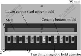
Fig.1 Traveling magnetic field generator calculation model
where t is the time, �� is the frequency of the current, and �� is the phase angle for which ��/�� represents a time- delay in the coil. From the Biot-Savart Law of magnetostatics, we can obtain the magnetic field in the space due to the current in the coil. One can show that the vector potential, A, due to the coil has only z-directional component, and given by[19]
![]()
In the absence of free charges in the space, the function A(x, y) is scalar function and given by[20]
![]()
where ��m is the magnetic permeability of the free space and equal to 4��10-7 H/m, and J1 is the first order Bessel function.
Using the vector potential, one can calculate the magnetic field B(y, t) and the electric field E(y, t) created by the current in the coil as
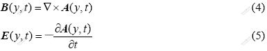
The current-loop creates a magnetic field in the x- and y-direction, and ��x component (direction of the current) of the magnetic field is zero.
Using the Ohm��s Law one can calculate the current density, j��, formed inside the liquid conductor, the current density in the conductor is, then, obtained as
![]()
where �� is the conductivity of the melt.
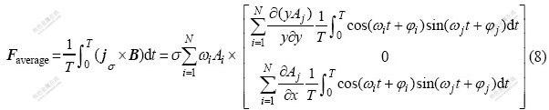
Furthermore, by neglecting the effect of the induced magnetic field due to the currents in the conductor, and the effect of the moving charges in the liquid conductor, we can also calculate the time-averaged Lorentz force F in the conducting melt as follows[18]:
![]()
Since the z-component of the magnetic field is zero, and the current is in the z-direction only, the Lorentz force also is in x- and y-direction only. For a single coil, from Eq.(7), one can show that the time-averaged Lorentz force acting on the liquid conductor. In the case of multiple coils, the time-averaged Lorentz force given in Eq.(7) becomes[18]
In the case of three coils,��1=��2=��3����, and ��1=0, ��2=2�ШM3, ��3=4�ШM3, one can show that Eq.(8) becomes
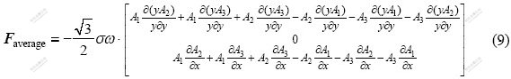
Eqs.(8) and (9) show that the multiple current carrying out-of-phase coils can create a body force in x-and y-directions; the force is zero in z-direction.
3 Computational models of TMF
Fig.1 shows the computational model of the TMF, the total length of the TMF is 726 mm, width 300 mm, height 110 mm, inter spacing of iron-teeth 32 mm, width of iron-tooth 22 mm, height of iron-tooth 38 mm, and coil cross-sectional area is 600 mm2.
Table 1 lists the properties and dimensions of some parameters used in simulations. TMF calculations are carried out for twelve coils, placed at yc=72 mm and xc=50, 104, 158, 212, 266, 320, 374, 428, 482, 536, 590, 644, and 698 mm equal magnitude currents with phase angles of 0, 2�ШM3, 4�ШM3,0, 2�ШM3, 4�ШM3,0, 2�ШM3, 4�ШM3,0, 2�ШM3, 4�ШM3, and different frequencies. We neglected the effect of the conductor in the traveling magnetic field, and the density, relative permeability, resistivity used in simulations are assumed to be constant, and the melt is considered as rigid body. Since the current is the in z-direction only and the z-component of the magnetic field is zero, so we set up two-dimension model for calculating. Then we apply the boundary condition that the magnetic flux is parallel to the border of the free space. And the vector diagram of electromagnetic force on Ga-In-Sn melt and the magnetic flux density in TMF are shown in Fig.2.
Table 1 Properties and dimensions of some parameters used in simulations
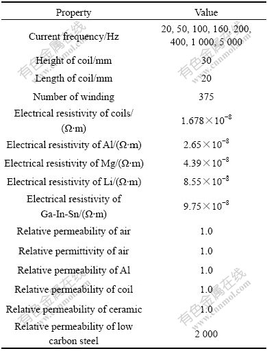
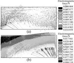
Fig.2 Vector diagram of electromagnetic force of Ga-In-Sn melt (a) and magnetic flux density (b) in TMF (f=50 Hz, I= 1 800 A)
4 Results and discussion
4.1 Experimental results and numerical simulations of electromagnetic force
The electromagnetic force on the melt in the TMF can be divided into Fx and Fy. The convection of the melt is driven by Fx, and Fy is the pulse force. Since it is difficult to measure the electromagnetic force directly, we use low melting point Ga-In-Sn melt, of which the melting point is about 10.2 �� to measure Fx. The flow status of the Ga-In-Sn melt is shown in Fig.3, it can be seen that the melt moving from left side to right side, and then accumulating at the end of the right side of the container. At the end of the left side of the container, the Ga-In-Sn melt is so little that we can see the bottom of the container. Meanwhile, the melt in the middle of the container is moving rightward, and the thickness of the melt increases from left to right side. A new apparatus designed to measure the Lorentz force is shown in Fig.4. Dimensions of the container are 300 mm��150 mm��3 mm, there are nine plastic tubes position at the right side of the container and a bigger one at the left side, the distance between the two tubes is 15 mm, and we can put the Ga-In-Sn melt into the container through the tube positioned at the left side of the container.
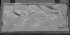
Fig.3 Flow status of Ga-In-Sn melt (f=50 Hz, I=1 272 A)

Fig.4 Apparatus for measuring the Lorentz force (f=50 Hz, I= 1 272 A)
The height of the melt in the tubes is higher than that in the container when the electromagnetic force applying on the melt. According to that, we can calculate the Lorentz force. So the results were recorded as the length of the melt changing in the TMF. Fig.5 shows the electromagnetic force of different lengths of the Ga-In-Sn melt in the TMF, the Lorentz force increases continually with the length increasing of the melt, and the measured values is compared with the results obtained by the numerical simulation, as we can see, the simulated course is very close to the experimental one. Note that the measurement of the Lorentz fore profile reproduces the computed one very well. These facts verify the correctness of the used simulation code and emphasize the reliability of the calculated TMF too.

Fig.5 Electromagnetic force on Ga-In-Sn melt with different lengths in TMF
4.2 Effects of current frequency and upper iron-core on electromagnetic force
Fig.6 shows the calculated horizontal time average Lorentz force profile. We calculated the time average Lorentz force profile of the melt with different current frequencies and different y, (y is the distance between the TMF generator surface and the melt surface). The time average Lorentz force profile is shown in Fig.6(a) for the container of the measuring apparatus without upper iron-core. The force first increases slightly, and then decreases rapidly as y approaches 7 mm. The TMF-induced Lorentz force increases with increasing frequencies, and the maximum value is 0.63 N when the current frequency is 160 Hz compared with 1.1 N in TMF with the iron-core shown in Fig.6(b), over that frequency the force decreases, in this case all the force are nearly zero at the height of 19 mm. In other case when the iron-core is activated, the force increases when the melt closes to the iron-core.
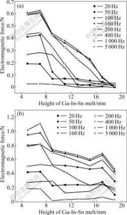
Fig.6 Curves of time-average Lorentz force of Ga-In-Sn melt at different heights under different current frequencies: (a) Without iron-core (b) With iron-core
The TMF concept emerged from recognizing deficiencies in the rotating magnetic field (RMF) technique to generate an optimal flow for solidification, the flow induced by the x-direction Lorentz force. The greater the differential forces of melts with different heights in x-direction are, the more intense the flow is. So the current frequency plays a more important role in the casting process, the ideal current frequency has chosen to master the flow. The forced convection is used for reducing the temperature gradient of solidification front, making the solute distribution homogeneous, and consequently changing the interface shape. However, when the convection is too intense, segregation will happen. The analysis shows that frequency in range of 100-200 Hz is the optimum condition for the fast casting, in this case the maximum value of the Lorentz force when the current frequency is 160 Hz is obtained by relatively lower power consumption, and in the rangeof 50-100 Hz and 200-400 Hz without iron-core, the turbulent flow is generated.
4.3 Electromagnetic force of metals with different conductivities
The electromagnetic forces on Ga-In-Sn, Li, Mg, Al melt were simulated, the horizontal Lorentz force profile and force vectors are presented in Fig.7, Figs.7(a)-(d) show the simulation fields of the horizontal Lorentz force distribution of the Ga-In-Sn, Li, Mg, Al respectively, the distributions of the force are similar, and the body force induced by the TMF is concentrated mostly near the surface of the TMF generator. The ratio of the electrical resistivity of the four materials, Ga-In-Sn, Li, Mg, and Al is 3.68:2.22:1.14:1, correspondingly. Due to the significant difference in electrical resistivity, the value of the Lorentz force increases linearly with the decreasing of electrical resistivity, and the time average Lorentz forces is as high as 1.279 55, 1.441 20, 2.640 19, and 3.719 55 N, respectively. The d?x/d�� decreases with the electrical resistivity increasing, the d?y/d�� (where �� is the electrical resistivity, the d?x/d�� and d?y/d�� are the slopes of the Lorentz force profile) increases with the increasing electrical resistivity, it is shown in Fig7(e), according to Eq.(9), the result reproduced the computed one very well. This fact demonstrates the correctness of the studied simulation model perfectly well.
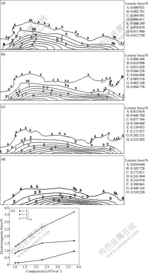
Fig.7 Simulation fields of horizontal Lorentz force distribution and electro- magnetic force-conductivity curves: (a) Ga-In-Sn melt; (b)Li melt; (c) Mg melt; (d) Al melt; (e) Force conductivity curve with TMF (I=1 800 A, f=50 Hz, ��=120?)
5 Conclusions
1) The electromagnetic force of the molten metal increases linearly with the increasing length of the melt under the TMF.
2) The TMF-induced time average Lorentz force increases with the increasing of frequencies, and the maximum value is obtained when the current frequency is 160 Hz, over that frequency the force decreases. In the case without the iron-core the force is nearly zero at the melt height of 19 mm. In other case when the iron-core is activated, the force increases when the melt closes to the iron-core.
3) The time average Lorentz force increases linearly as the electrical resistivity decreasing. And the d?x/d�� decreases with the increasing of electrical resistivity, while the d?y/d�� increases with the increasing of electrical resistivity.
References
[1] SHINMURA T, YAMAGUCHI H. Study on a new internal finishing process of a nonferromagnetic tube by the application of a linearly traveling magnetic-field on the process principle and the behaviors of magnetic finishing tool [J]. International Journal of the Japan Society for Precision Engineering, 1994, 28(1): 29-34.
[2] TANAKA Y, SASSA K, IWAI K. Separation of nonmetallic inclusions from molten-metal using traveling magnetic field [J]. Journal of the Iron and Steel Institute of Japan, 1995, 81(12): 1120-1125.
[3] ONO N, TRAPAGA G. A numerical study of the effects of electromagnetic stirring on the distributions of temperature and oxygen concentration in silicon double-crucible Czochralski processing [J]. Journal of the Electrochemical Society, 1997, 144: 764-472.
[4] TOMZIG E, VIRBULIS J, von AMMON W, GELFGAT Y, GORBUNOV L. Application of dynamic and combined magnetic fields in the 300 mm silicon single-crystal growth [J]. Materials Science in Semiconductor Process, 2003, 5: 347-351.
[5] ABRICKA M, GELFGAT Y, KRUMINS J. Influence of combined electromagnetic fields on the heat/mass transfer in the Bridgman process [J]. Energy Conversion and Management, 2002, 43: 327-333.
[6] ZAIDAT K, OULED-KHACHROUM T, VIAN G, GARNIER C, MANGELINCK-NOEL N, DUPOUY M D, MOREAU R. Directional solidification of refined Al�C3.5wt% Ni under natural convection and under a forced flow driven by a traveling magnetic field [J]. J Crystal Growth, 2005, 275: 1501-1505.
[7] SCHWESIG P, HAINKE M, FRIEDRICH J, MUELLER G. Comparative numerical study of the effects of rotating and travelling magnetic fields on the interface shape and thermal stress in the VGF growth of InP crystals [J]. J Crystal Growth, 2004, 266: 224-228.
[8] MAZURUK K, RAMACHANDRAN N, VOLZ M P. Use of traveling magnetic fields to control melt convection [C]// Conference on Materials Research in Low Gravity, 1999: 19-21.
[9] MEDINA M, DU TERRAIL Y, DURAND F, FAUTRELLE Y. Channel segregation during solidification and the effects of an alternating traveling magnetic field [J]. Metallurgical and Metals Transactions B��Process Metallurgy and Materials Processing Science, 2004, 4: 743-754.
[10] KUNSTREICH S. Electromagnetic stirring for continuous casting��Part I [J]. Revue De Metallurgie-cahiers D Information Techniques 2003, 100(4): 395-408.
[11] ZAIDAT K, MANGELINCK-NOEL N, MOREAU R. Control of melt convection by a traveling magnetic field during the directional solidification of Al-Ni alloys [J]. Comptes Rendus Mecanique, 2007, 335(5): 330-335
[12] TOMZIG E, VIRBULIS J, VON AMMON W, GELFGAT Y, GORBUNOV L. Application of dynamic and combined magnetic fields in the 300 mm silicon single-crystal growth [J]. Materials Science in Semiconductor Processing, 2002, 5(4/5): 347-351.
[13] KRAUZE A, MUIZNIEKS A, MUHLBAUER A, WETZEL T, GORBUNOV L, PEDCHENKO A, VIRBULIS J. Numerical 2D modelling of turbulent melt flow in CZ system with dynamic magnetic fields [J]. J Crystal Growth, 2004, 266(1/3): 40-47.
[14] GREER A L, BUNN A M, TRONCHE A, EVANS P V, BRISTOW D J. Modeling of inoculation of metallic melts: Application to grain refinement of aluminium by Al-Ti-B [J]. Acta Materialia, 2000, 48(11): 2423-2835.
[15] GANDIN C A. From constrained to unconstrained growth during directional solidification [J]. Acta Materialia, 2000, 48(10): 2483-2501.
[16] LIU S, LU S Z, HELLAWELL A. Dendritic array growth in the systems NH4Cl-H2O and [CH2CN](2)-H2O: The detachment of dendrite side arms induced by deceleration [J]. J Crystal Growth, 2002, 234(4): 740-750.
[17] VANDYOUSSEFI M, GREER A L. Application of cellular automaton-finite element model to the grain refinement of directionally solidified Al-4.15 wt% Mg alloys [J]. Acta Materialia 2002, 50(7): 1693-1705.
[18] YESILYURT S, MOTAKEF S, GRUGEL R, MAZURUK K. The effect of the traveling magnetic field (TMF) on the buoyancy-induced convection in the vertical Bridgman growth of semiconductors [J]. J Crystal Growth, 2004, 263(1/4): 80-89.
[19] JACKSON J D. Classical electrodynamics [M]. New York: Wiley, 1975.
[20] DERBY J J, ATHERTON L J, GRESHO P M. An integrated process model for the growth of oxide crystals by the Czochralski method [J]. J Crystal Growth, 1989, 97(3/4): 792-826.
Foundation item: Project supported by the Program of Excellent Team in Harbin Institute of Technology, China
Corresponding author: SU Yan-qing; Tel: +86-451-86417395; +86-451-86418415; E-mail: suyq@hit.edu.cn
DOI: 10.1016/S1003-6326(09)60195-3
Abstract: A new apparatus was designed to measure the electromagnetic force and a computational study of the traveling magnetic field (TMF) and its application to the Ga-In-Sn melt (with low melting point), then the forces on Al, Mg, and Li melt, were simulated. The result show that the electromagnetic force on the melt increases linearly with the increasing length of the melt in the TMF. The TMF-induced Lorentz force increases with increasing frequency, and then decreases. The maximum value is obtained when the current frequency is 160 Hz, over that frequency the force decreases rapidly. When the iron-core is activated, the force increases when the melt closes to the iron-core. The Lorentz forces have inversely-proportional relationships with the electrical resistivity, the d?x/d�� decreases and the d?y/d�� increases with the increasing electrical resistivity (d?/d�� is the slope of the Lorentz force profile).
