

J. Cent. South Univ. (2018) 25: 38-50
DOI: https://doi.org/10.1007/s11771-018-3715-x

Effect of montmorillonite on hydrate-based methane separation from mine gas
ZHANG Qiang(��ǿ)1, 2, 3, WU Qiang(��ǿ)2, 3, ZHANG Hui(�Ż�)1,ZHANG Bao-yong(�ű���)2, 3, XIA Ting(����)3
1. School of Materials Science and Engineering, Harbin University of Science and Technology,Harbin 150080, China;
2. Department of Safety Engineering, Heilongjiang University of Science & Technology,Harbin 150022, China;
3. National Central Laboratory of Hydrocarbon Gas Transportation Pipeline Safety, Harbin 150022, China
 Central South University Press and Springer-Verlag GmbH Germany,part of Springer Nature 2018
Abstract:
Three types of mine gas samples were used in the solutions of tetrahydrofuran (THF), sodium dodecyl sulfate (SDS) and THF-SDS with/without MMT respectively to investigate the effect of montmorillonite (MMT) on separation characteristics of methane recovered from mine gas based on hydrate method. The partition coefficient, separation factor and recovery rate were used to evaluate the effects of MMT, and the selection factor was primarily proposed to define the selectivity of mine gas hydrate in the relative target gases. The experimental results indicate that MMT could improve the following factors including hydration separation factor, the selection factor, the partition coefficient, and the recovery rate. Furthermore, the effect of SDS on the function of MMT is analyzed in the process of hydration separation. Finally, due to the results of the experiment, it is concluded that MMT hydration mechanism explores the effect of MMT enrichment methane from mine gas.
Key words:
Cite this article as:
ZHANG Qiang, WU Qiang, ZHANG Hui, ZHANG Bao-yong, XIA Ting. Effect of montmorillonite on hydrate-based methane separation from mine gas [J]. Journal of Central South University, 2018, 25(1): 38�C50.
DOI:https://dx.doi.org/https://doi.org/10.1007/s11771-018-3715-x1 Introduction
Methane (CH4) is a kind of greenhouse gas with the greenhouse effect 21 times that of CO2 and it takes up 18% of the global greenhouse effects [1]. The environmental protection agency (EPA) estimates that coal mine methane holds 8%�C10% of human-made methane emissions worldwide. A key source of methane emissions in China is coal production, whereas Russia emits most of its methane from natural gas and oil systems. Reducing methane emissions takes a large amount of important energy and safety, economic, and environmental benefits [2]. Thus, the collection and utilization of methane provides a valuable and clean-burning energy source that improves quality of life in local communities and can generate revenue and improve living standards.
Instead of releasing methane to the atmosphere, profitable method for the methane can be identified and implemented. WU et al [3] proposed a new method using coal mine gas separation based on hydrate technology in 2009. Various view points should be considered to choose a more appropriate separation process depending on the desired separation product. There are two key factors for the evaluation of separation performances: separation efficiency and the production rate. Economic studies for such processes mainly focus on the price of the promoters needed to reduce the pressure and increase the temperature of the separation steps because the design of the other required equipment is generally simple [4]. It seems that the industry will be interested in such investments when the environmental regulations are rigid and the coal mine gas reserves tend to reach their half-lives. There are mechanical and chemical methods to promote the gas hydrate formation or gas separation. The mechanical methods mainly include agitation [5], spray [6], and microbubbles [7], while the chemical methods mainly consist of surfactants and the crystal seeds. However, the disadvantages of the mechanical method are the large power consuming and complex process.
The simple chemical method is widely used in the past, and currently the dynamics accelerator sodium dodecyl sulfate (SDS) and the thermodynamic accelerator tetrahydrofuran (THF) are applied widely. The main function of SDS is to reduce the surface tension of liquid phase, which has the effect of solubilization and can increase the gas content of the hydrate phase [8]. Under the same temperature condition, the pressure of THF hydrate phase equilibrium is lower, and then THF can form the basis of gas hydrate to provide the material foundation for gas hydrate and reduce the gas hydrate phase equilibrium condition [9]. However, SDS and THF are not selective, and the mine gas is kind of mixed gas where each gas component can form the hydrate. Therefore, the difference of promoting effect on gas between SDS and THF is not very obvious. As a result, the application of the hydrate-based separation technique is not very mature. Montmorillonite is the most common mineral in the nature and gas hydrates are widely present in the sediments [10]. Montmorillonite is considered to be one of the gas hydrate fingerprints [11] and has a good quality of water swelling, adhesion and adsorption properties [12]. It can be considered as a kind of carrier in the hydrate-based separation method. Series of results of the gas hydrate formation capability of montmorillonite (MMT) are recorded as followed. CHA et al [13] found that gas hydrate has a higher temperature and lower stable steady pressure (296.1 K and 5.54 MPa) with MMT present, comparing with pure water system (295.7 K and 8.28 MPa). The surface adsorption of MMT makes it easier to form gas hydrates, OUAR et al [14] confirmed the former view by experiments. KOTKOSKIE et al [15] found that the reserves of gas hydrate are higher with MMT present by geological survey. CYGAN et al [16] first compounded methane hydrate in the interlayer of MMT and studied the stability of the hydrate layer within the temperature and pressure range. It was proved that methane molecules can enter the MMT and form stable hydrate [16]. By computer simulation, PARK et al [17] found that MMT can form the stable cage-type structure of methane. Research scholars indicated that MMT had a role of promoting hydrate formation and selecting adsorption character for CH4 [18, 19].
In summary, the methane hydrate formation can be promoted by the addition of MMT, which is used to explore the method to improve the efficiency of methane recovery from the coal mine by hydrate separation. The author conducts the mine gas hydrate separation experiment in different mixture systems of MMT, SDS and THF and sets up the blank test as well. Simultaneously, the effect of MMT on coal mine gas hydrate separation is examined and its mechanism is analyzed. The separation effect is evaluated by the separation difficulty, purification degree and product quantity. For the separation difficulty, it is determined by the partition coefficient, while the purification degree and the product quantity depend on the separation factor and the recovery rate. The separation experiments are conducted with the methane concentration of 24.90%, 40.40% and 59.50%, respectively.
2 Experimental
2.1 Apparatus and material
A visual high pressure apparatus was developed to conduct gas hydrate formation experiment for mine gas separation, as shown in Figure 1.
The experimental apparatus mainly included high pressure cell, thermotank, vacuum pump, data collection system, fiber photography system and gas chromatography. The reactor held the volume of 150 mL, with a maximum pressure of 20 MPa. The operation temperature for the thermotank ranged from 263.15 K to 323.15 K. The gas chromatograph GC-4000A was suitable to analyze the mole fraction of gases, with the sensitivity of 0.01%.

Figure 1 Schematic illustration of hydrate formation experimental set-up
The reagents used in the experimental systems are listed in Table 1. The gas sample mole fraction compositions are as followed: sample A x(CH4)= 24.90%, x(N2)=60.20%, x(O2)=4.90%; sample B: x(CH4)=40.40%, x(N2)=49.50%, x(O2)=10.10%; sample C: x(CH4)=59.50%, x(N2)=35.20%, x(O2)= 5.30%. The amount of MMT was 1.5 g, and the volume of all reactors was 60 mL. The concentrations of SDS and THF were 0.50 mol/L and 0.10 mol/L (a better hydration separation rate obtained in the previous experiment at this concentration [20]) and water was distilled.
2.2 Procedure
Each experimental procedure was performed according to the following steps:
2.2.1 Preparation process of experimental system
1) In the typical separation experiment, the reactor was first vacuumed and a certain amount of solution (MMT, SDS, THF) of 60 mL was then loaded into the reactor using the liquid feed pump.
Table 1 Reagents and materials of experimental system

2) Pure nitrogen was poured into the system rapidly with the pressure up to 7 MPa, measuring the air tightness of experimental system.
3) The vacuum pump could ensure that the reactor was thoroughly clean and air was absent.
4) The gas samples were full of the hydration reactor up to 6 MPa by the pressurization system, recording real-time temperature of thermotank.
5) The thermotank was set to 274.15 K.
2.2.2 Gas hydrate formation
6) Macroscopic phenomena of gas hydrate formation were detected by fiber photography system.
7) During the experiment, temperature and pressure in the system were recorded.
8) When the pressure in the reactor was stable, evacuate the residual gas.
9) Gas hydrate was dissociated recording the temperature and pressure of reactor.
2.2.3 Gas chromatography
10) Determination of methane concentrations of the vapor phase: an equilibrium state of three- phase coexistence was established and the equilibrium composition was measured. The vapor phase was analyzed at least 3 times by gas chromatography (the sample volume was 100 ��L using the GC4000A gas chromatograph). The average concentration was then taken as an equilibrium vapor-phase composition.
11) Determination of methane concentrations of the hydrate phase: when the corresponding vapor phase compositions were measured and the vapor- phase analysis was finished, the reactor was evacuated to ensure the gas was absent. The hydrate in the reactor was then dissociated by increasing the temperature gradually until vapor and water formed, and the gas composition in hydrate phase was analyzed by gas chromatography.
3 Results and discussion
3.1 Gas hydrate morphology in reactor
Evidence from visual observation of natural and laboratory grown hydrate was that hydrate took a variety of morphologies which depended on host molecules.
The hydrate formation process in system IV was observed and depicted in this work. A small amount of white granular hydrate crystals appeared on liquid surface after 57 min of test, as shown in Figure 2(a). With the experiment proceeding to 82 min, the solution surface quickly became jagged and exhibited a certain amount of white foamy solid crystals, as demonstrated in Figure 2(b). As the reaction proceeded to the moment of 137 min, a large number of white flocculent hydrates were generated, as shown in Figure 2(c). When the reaction reached 276 min, hydrates were formed as a unit, and it is macroscopically indicated that gas hydrate formation is finished, as seen in Figure 2(d). At that moment, the pressure in the cell was stable, quantitatively indicating that the hydrate formation is finished.
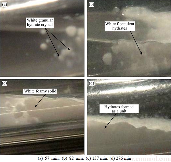
Figure 2 Typical pictures of hydrate formation in experimental reactor 4�C1 (MMT free):
For test 4�C2, the flocculent white hydrate formed at gas�Cliquid interface after the refrigeration of 45 min, and large ice-shaped white hydrates appeared on liquid surface of the reactor, as illustrated in Figure 3(a). After 61 min, more white ice-shaped hydrate crystals appeared around the different positions of the reactor. The hydrates grew increasingly and covered most part of the liquid surface as shown in Figure 3(b). At 73 min, the white hydrate crystals became larger. White hydrate grew massively, as shown in Figure 3(c). After 234 min of refrigeration, a large number of white hydrate crystals formed and solution has almost wholly changed into solid, as shown in Figure 3(d).
3.2 Calculations for partition coefficient, separation factor, recovery rate
This work adopted partition coefficient, separation factor and recovery rate to evaluate the separation efficiency based on hydrate technology.
In the chemical and pharmaceutical perspectives, the two phases are often restricted to two immiscible solvents. In this work, the partition coefficient is the ratio of concentrations of the compound in the two phases of two immiscible liquids at equilibrium [21]. Hence the coefficient is the factor to measure differential solubility of the compound between these two solvents. In this work, partition coefficient (K) reflects the transfer ability and separation efficiency of methane in residual gas phases and hydrate phases.
 (1)
(1)
where  and
and  represent the mole fractions of hydrate and residual gas phases, respectively.

Fig. 3 Typical pictures of hydrate formation in experimental reactor 4�C2 (MMT present):
Two parameters, recovery rate (Rr) and separation factor (Fs), are introduced, ignoring the impact of gas hydrate growth on residual gas volume. Methane is separated from coal mine gas by gas hydrate formation. The decomposition of hydrate is carried out at room temperature (about 293 K) by reducing pressure inside the reactor to the atmospheric pressure. After decomposition of the recovered hydrate, the generated gas is analyzed by the gas chromatograph (GC4000A) to determine the components. The gas recovery rate Rr in hydrate phase is expressed by [22]:
 (2)
(2)
where  and
and  represent the total number of methane moles of the feed gas and in hydrate phase, respectively. For the mixed gas, the separation factor Fs is calculated using the following equation [23]:
 (3)
(3)
where y is mole fraction; subscripts ��feed��, ��H�� and ��gas�� represent feed gas, hydrate and residual gas, respectively. Subscripts ��CH4��, ��N2�� and ��O2�� are defined as the number of methane, nitrogen molecules and oxygen molecules in hydrate and residual gas phases, respectively.
The gas mole fraction is calculated combined with Clapeyron equation as
 (4)
(4)
The compression factor is calculated as [24]
 (5)
(5)
where Z0 and Z1 are the complex functions of pr and Tr, respectively; �� is defined as a centric factor.
There is a similar linear relationship between the logarithmic of comparative vapor pressure and absolute temperature [25].
 (6)
(6)
where  is critical saturated vapor pressure, Tr is reduced temperature, a and b represent correction factors, determined by the critical point:

 (7)
(7)
 (8)
(8)
where pr is reduced pressure, pc is critical pressure, Tc is critical temperature and �� is defined as acentric factor by Pitzer.
Substituting Eq. (8) into Eq. (5) yields:
 (9)
(9)
where Z0 and Z1 are calculated by the Pitzer compression factor table [25].
Substituting Z into Eqs. (2)�C(3) yields:
 (10)
(10)
where P in Table 2 is defined as the partial pressure; V is gas volume and Z is the compressibility factor in different phases, respectively.
3.3 Evaluation of effect of MMT by developed equations
The partition coefficient, separation factor and recovery rate are shown in Table 3, which shows the mole fraction of methane in the hydrate phase with MMT present for sample A. It is increased by 3.02%, 2.64% and 10.59%, respectively, comparing with the MMT free. For sample B, in the reactors 4�C2, 5�C2 and 6�C2, the methane concentrations reaches 67.28%, 56.43% and 62.36%, respectively with MMT present, which are 12.05%, 5.84% and 6.50% larger than systems MMT free 4�C1, 5�C1 and 6�C1. For sample C, in the hydrate phase reactors 7�C2, 8�C2 and 9�C2, the concentrations of methane increase by 6.09%, 0.15% and 7.09%, respectively, by adding MMT. The separation concentration of methane increases from 0.15% to 12.05%, which indicates that MMT can increase the concentration of CH4 of hydrate phase with the experimental range.
In equilibrium state, the concentration coefficient of the partition component in the stationary phase and mobile phase is called partition coefficient. It reflects the degree of difficulty for gas separation.
According to the data in Table 3 and the curve in Figure 4, it shows that the partition coefficients of the three kinds of mine gas samples in MMT are higher than that of the MMT free. Meanwhile, the partition coefficient of mine gas hydrate in THF and THF-MMT system is lower, and it indicates that the addition of SDS could reduce the difficulty of the mine gas hydrate separation and promote the mine gas entering the liquid phase, which has the effect of solubilization. By comparing the partition coefficients of the three kinds of mine gas hydrate, it is found that sample B is less difficult to be separated than sample A and sample C when adding the same additive.
Table 2 Hydration separation results of each experimental system
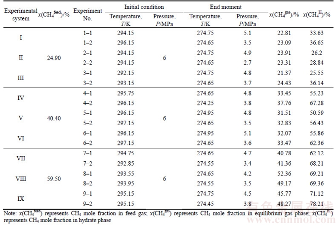
Table 3 Partition coefficient, separation factor, selection factor and recovery rate for each experimental system

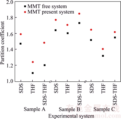
Figure 4 Distribution of partition coefficient in different systems
Coordinate is used to reflect CH4 in mine gas selected by the hydrate separation system, as shown in Figure 5. Taking sample A for example, the initial state of CH4 concentration in the gas phase is 24.9%, and the concentration of CH4 in the hydrate phase is 0, thus the coordinate point is recorded as (24.9%, 0). As a result, the initial coordinates of CH4 in sample B and sample C are (40.4%��0) and (59.5%, 0), respectively. The ideal separation state of CH4 in mine gas with the method of mine gas hydrate is that CH4 concentration in the hydrate phase is 100% and the residual in the gas phase is 0, denoted (0, 100%). However, hydrate growth process is divided into nucleation stage and growth stage. The growth stage is mainly the adsorption process. Once the basic hydrate is formed, the subsequent hydrate grows based on the hydrate structure which has been formed by sharing the surface and bond of hydrate crystal cavity [26�C28]. The mechanism of separating the mixed gas by the method of hydrate separation is that the difference of the hydrate phase equilibrium pressure of various kinds of gas is obvious at the same temperature. The gas with lower phase equilibrium pressure is made to form the hydrate by controlling the pressure, so that it could be enriched in the hydrate phase to achieve the purpose of separation. However, when the phase equilibrium pressure is lower and the basic hydrate of mine gas is formed, the other gases could enter into the hydrate phase state, even if they did not reach the phase equilibrium conditions of hydrate formation, in order to affect the concentration of mine gas that the hydrate phase is enriched. Therefore, the hydration method is applied to separate the mixed gas at present and the separating concentration could not reach the ideal separation state (0, 100%), as shown in Figure 5. The concentrations of CH4 in the gas phase and hydrate phase are noted as abscissa and ordinate respectively and formed the coordinate system after the hydrate separation. It is analyzed that the separating point could not appear in regions B and C in the image. If the purified gas concentration of the target is far less than that of the other gas components, the collision frequency of the gas with higher concentration to the hydrate lattice is higher after the basic hydrate formation. The probability of reaching the hydrate phase state is higher as well. In this particular case, the separated gas concentration point was possible in the region D, and it would not appear in region A under normal circumstances. Therefore, when the point of the separating gas concentration is closer to the ideal points (0, 100%), it indicated that the hydrate selects CH4 more obviously. The distance between the gas separation point and the ideal point in the curve is calculated and the distance is defined as selection factor, denoted as
 (11)
(11)
According to the results of the calculation shown in Table 3 and Figure 5, it is found that the selection factor of MMT present system is smaller, which demonstrates that MMT could improve the enrichment concentration of hydrate for CH4.
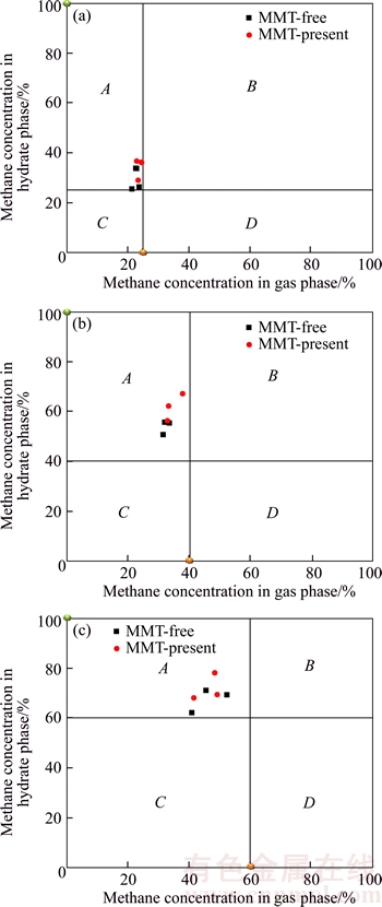
Figure 5 Distribution of methane concentration in residual gas phases and hydrate phase
The results of the calculation of the separation factor Fs are presented in Figure 6. It is clear that the separation factors Fs for MMT present systems ranged from 1.78 to 14.8 while those for MMT free systems ranged from 1.21 to 8.51 and they are higher than those for MMT free systems, indicating MMT could promote the coal mine gas purification based on hydrate method. For gas sample A with methane concentration of 24.9%, the separation factors Fs is increased from 1.21 to 2.94 in MMT free systems while it is from 1.78 to 3.71 in MMT present systems. For gas sample B with methane concentration of 40.4%, the separation factors Fs is from 4.95 to 7.19 in MMT free systems and the number value is 7.94 to 13.21 in MMT present systems. For gas sample C with methane concentration of 59.5%, the separation factors Fs is up from 4.18 to 8.51 in MMT free systems while from 5.48 to 14.8 in MMT present systems. It is obvious that MMT has more notable purification effect on the gas samples B and C than A. It may be estimated that with the methane concentration increasing, purification effect for MMT is more notable.
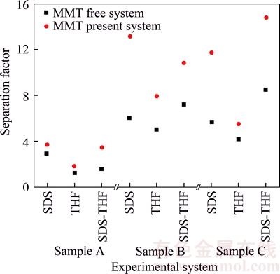
Figure 6 Distribution of separation factor in different systems
Furthermore, when it appears the same methane concentration in the feed gas, the hydrate separation factor is in the minimum state in the experimental system without SDS, indicating that SDS could improve the degree of separation purification, and THF plays a role of reducing the degree of purification.
As seen Figure 7, it is indicated that the recovery rates are much larger for MMT present systems than those for systems MMT free, implicating that MMT benefited for more methane recovery from coal mine gas. The methane recovery rate of THF-MMT system is lower than that of SDS-MMT system and SDS-THF-MMT system for the same feed gas.
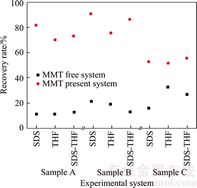
Figure 7 Distribution of recovery rate in different systems
The results of the experiment are analyzed and it is found that MMT has the effect of improving the gas content of the mine gas hydrate phase, and has a certain function of selecting CH4. It is believed that MMT minerals have a higher specific surface area and abundant interlayer charge (Figure 8); the radius of the particle is between 0.2�C2.0 ��m; the specific surface area is large enough, which makes it have a relatively strong adsorption capacity [29, 30]. MMT layers form a stable methane clathrate structure, and 0.5 methane molecules could be formed in each lattice. Methane molecule is nested within the six-membered ring of the clay [31]. One side reacts with the interlayer water and the other side reacts with the silico- oxygen tetrahedron layer (Figure 9). EDS analysis shows that the structure of MMT is the same as the clathrate structure of the granular gas hydrate, indicating that surface adsorption of the MMT makes the gas hydrate formation easily. MMT provides the basic platform for gas hydrate formation to increase methane content in the hydrate phase. Therefore, the separation factor is increased, improving the gas hydrate purification degree. It is also proved that using MMT could enhance the enrichment capability of methane in the hydrate, improve the mole fraction of methane in the hydrate phase and meet the purpose of separation and purification of low-concentration gas.
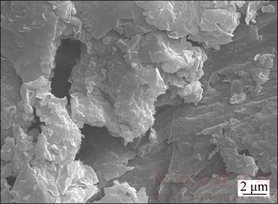
Figure 8 Micrograph of MMT
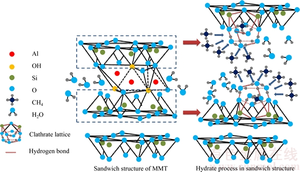
Figure 9 Mechanical model of MMT promoting hydrate formation
By adding MMT, the enrichment and selection of CH4 is relatively weaker in THF-MMT system, because THF could form hydrate before gas, which consumes more material basis and affects the gas storage capacity of hydrate. SDS is used to reduce the surface tension of liquid phase and improve the gas entering into the liquid phase, which has the effect of solubilization and increases the gas content of the hydrate phase, which has been confirmed by many scholars [32, 33]. The author believes that MMT is a kind of clay which is insoluble in water and the density is higher than water, therefore, the precipitation is formed in liquid phase and could not easily reach the gas, so as to weaken its function in the process of hydrate separation. Contrastively, SDS has the function of suspension and the SDS and MMT compound solution could make the MMT suspend and dispersed uniformly in the liquid phase, which increases the probability of MMT in contact with the gas phase and provides the conditions for MMT promotion in hydrate separation process. As a result, it is possible to improve the gas storage ability of gas hydrate phase and enhance the selectivity and enrichment of gas hydrate phase for CH4 by adding SDS and MMT together.
4 Conclusions
In this work, the idea of hydrate formation in MMT-accelerator system is suggested for N2 and O2 gaseous mixture to apply CH4 separation process. Compared with systems MMT free, adding MMT could increase the separation factor, partition coefficient and the recovery rate, providing an enhanced result for CH4 separation through gas hydrate formation. Meanwhile, the author primarily proposes the definition of selection factor to define the enrichment ability of hydrate in the relative target gases. Through the analysis, the MMT has the selective enrichment effect on CH4. The promotion performance of MMT may be related to its surface adsorption and it provides the basic platform for gas hydrate formation easily in the separation process. MMT would take a better consequence by adding SDS and MMT together. The hydrate formation kinetics would be investigated and measured in near future work. At the same time, the effect of MMT and SDS with varying concentration will be studied in mine gas hydrate separation process in the next step, so that the best compound concentration could be selected.
References
[1] TAKAHISA U. Development of coal mine methane concentration technology for reduction of greenhouse gas emissions [J]. Science China (Technological Sciences), 2010, 40 (1): 28�C32.
[2] LI Kong-zhai, WANG Hua, WEI Yong-gang, AO Xian-quan, LIU Ming-chun. Partial oxidation of methane to synthesis gas using lattice oxygen [J]. Progress in Chemistry, 2008, 20(9): 1306�C1314.
[3] WU Qiang, ZHANG Qiang, ZHANG Bao-yong. Influence of super-absorbent polymer on the growth rate of gas hydrate [J]. Safety Science, 2012, 50(4): 865�C868.
[4] LINGA P, KUMAR R, ENGLEZOS P. The clathrate hydrate process for post and pre-combustion capture of carbon dioxide [J]. Journal of Hazardous Materials, 2007, 149(3): 625�C629.
[5] SEBASTIEN B, JUAN G B, PHILLIP S. Reaction rate constant of methane clathrate formation [J]. Fuel, 2010, 89(2): 294�C301.
[6] NIMALAN G, ROBERT A. Modelling hydrate formation kinetics of a hydrate promoter-water-natural gas system in a semi-batch spray reactor [J]. Chemical Engineering Science, 2004, 59(18): 3849�C3863.
[7] TAKAHASHI M, KAWAMURA T, YAMAMOTO Y, OHNARI H, HIMURO S Z, SHAKUTSUI H. Effect of shrinking microbubble on gas hydrate formation [J]. The Journal of Chemical Physics B, 2003, 107(10): 2171�C2173.
[8] ZHONG Y, ROGERS R E. Surfactant effect on gas hydrate formation [J]. Chemical Engineering Science, 2000, 55(19): 4175�C4187.
[9] MAKOGON T Y, LARSEN R, KNIGHT C A, SLOAN E D. Melt growth of tetrahydrofuran clathrate hydrate and its inhibition: method and first results [J]. Journal of Crystal Growth, 1997, 179(1, 2): 258�C262.
[10] CLENNELL M B, HOVLAND M, BOOTH J S, HENRY P, WINTERS W J. Formation of natural gas hydrates in marine sediments: Conceptual model of gas hydrate growth conditioned by host sediment properties [J]. J Geophys Res, 1999, 104(B10): 22985�C23003.
[11] BEATRICE C, MIRKO F, ANDREA N, FRANCO C, FEDERICO R. Carbon dioxide capture using gas hydrate technology [J]. Journal of Energy and Power Engineering, 2013, 7(5): 883�C890.
[12] PETERS A, CANDAU S J. Kinetics of swelling of spherical and cylindrical gels [J]. Macromolecules, 1988, 21(7): 2278�C2282.
[13] CHA S B, OUAR H, WILDEMAN T R. A third-surface effect on hydrate formation [J]. The Journal of Physical Chemistry, 1988, 92(23): 6492�C6494.
[14] OUAR H, CHA S B, WILDEMAN T R. The formation of natural-gas hydrates in water-based drilling-fluids [J]. Transactions of I Chem E (A), 1992, 70(1): 48�C54.
[15] KOTKOSKIE T S, AL-UBALDI B, WILDEMAN T R, SLOAN E D. Inhibition of gas hydrates in water-based drilling muds [J]. SPE Drilling Engineering, 1992, 7(2): 130�C136.
[16] CYGAN R T, GUGGENHEIM S, GROOS A F K. Molecular models for the intercalation of methane hydrate complexes in montmorillonite clay [J]. The Journal of Physical Chemistry B, 2004, 108(39): 15141�C15149.
[17] PARK S H, SPOSITO G. Do montmorillonite surfaces promote methane hydrate formation? Monte Carlo and molecular dynamics simulations [J]. The Journal of Physical Chemistry B, 2003, 107(10): 2281�C2290.
[18] TITILOYE J O, SKIPPER N T. Molecular dynamics simulation of methane in sodium montmorillonite clay hydrates at elevated pressures and temperatures [J]. Molecular Physics, 2001, 99(10): 899�C906.
[19] REYNOLDS J A, TANFORD C. The gross conformation of protein-sodium dodecyl sulfate complexes [J]. The Journal of Biological Chemistry, 1970, 245(19): 5161�C5165.
[20] WU Qiang, ZHANG Bao-yong. The effect of THF-SDS on separation of methane-hydrate from mine gas [J]. Journal of China University of Mining & Technology, 2010, 39(4): 484�C489. (in Chinese)
[21] LEO A, HANSCH C, ELKINS D. Partition coefficients and their uses [J]. Chem Rev, 1971, 71(6): 525�C616.
[22] LINGA P, KUMAR R, ENGLEZOS P. The clathrate hydrate process for post and pre-combustion capture of carbon dioxide [J]. Journal of Hazardous Materials, 2007, 149(3): 625�C629.
[23] LI Xiao-sen, XU Cun-gang, CHEN Zhao-yang, WU Hui-jie. Hydrate-based pre-combustion carbon dioxide capture process in the system with tetra-n-butyl ammonium bromide solution in the presence of cyclopentane [J]. Energy, 2011, 36(3): 1394�C1403.
[24] LEE B I, KESLER M G. Generalized thermodynamic correlation based on three-parameter corresponding states [J]. AIChE Journal, 1975, 21(3): 510�C527.
[25] ELLIOTT J R, LIRA C T. Introductory chemical engineering thermodynamics. [M]. 2nd Edition. New York: Prentice Hall, 2012: 60�C62.
[26] VYSNIAUSKAS A, BISHNOI P R. A kinetic study of methane hydrate formation [J]. Chem Eng Sci, 1983, 38(7): 1061�C1072.
[27] VYSNIAUSKAS A, BISHNOI P R. Kinetics of ethane hydrate formation [J]. Chem Eng Sci, 1985, 40(2): 299�C303.
[28] LI Li, XU Hai-liang, YANG Fang-qiong. Three-phase flow of submarine gas hydrate pipe transport [J]. Journal of Central South University. 2015, 22: 3650�C3656.
[29] MILLER F P, VANDOME A F, MCBREWSTER J. Montmorillonite [M]. Beau Bassin: Alphascript Publishing, 2010: 10�C16.
[30] GUO Yu-ting, DONG Fa-qin, LIU Ming-xue, QIN Yong-lian, ZHOU Qing, WU Chuan-long, ONG Mei-rong, HUANG Ting, LIU Yuan-yuan. Adsorption characteristics and mechanism of glycine on montmorillonite in aqueous solutions [J]. Journal of Central South University (Science and Technology), 2016, 47(4): 1092�C1099. (in Chinese)
[31] GAYET P, DICHARRY C, MARION G, GRACIAA A, LACHAISE J, NESTEROV A. Modeling heating curve for gas hydrate dissociation in porous media [J]. Chemical Engineering Science, 2005, 60(21): 5751�C5758.
[32] KARAASLAN U, PARLAKTUNA M. Effect of surfactants on hydrate formation rate [J]. Annals of the New York Academy of Sciences, 2000, 912(1): 735�C743.
[33] BAHRI Z, REZAI B, KOWSARI E. Selective separation of gallium from aluminum in SDS�CGa�CAl and SDS�CGa�CAl�C fluoride systems by ion flotation [J]. Journal of Central South University, 2017, 24(04): 789�C795.
(Edited by FANG Jing-hua)
���ĵ���
����ʯ��ˮ�������ú����˹�м����Ӱ��
ժҪ������˹���Լ���(CH4)Ϊ���Ļ�����壬CH4�ǽྻ����Ч��������Դ��ͬʱ��Ҳ�ǶԳ����ƻ�������ǿ���������塣������Ũ�Ƚϵͣ�ʹ�ó����˹��ֱ�����ã�����ˮ����ܹ������ᴿ�����˹��CH4�����÷����Ĺؼ���ѧ��������μӿ�ˮ�Ϸ������ʣ�������˹ˮ���ﴢ���������CH4�����ʡ�����ʯ(MMT)���нϺõ������Ժ�ճ���ԣ������о���������ʯ�ܹ��ٽ�����ˮ�����γɡ��ݴ����3����˹�����ֱ���MMT-SDS��MMT-THF��MMT-SDS-THF���հ���ϵ�н�����˹ˮ�Ϸ���ʵ�飬������MMT����˹ˮ�Ϸ���Ч�ʡ�CH4�����ʵ�Ӱ����ɡ���������� MMT�ܹ�������˹ˮ�Ϸ������Ӻͷ���ϵ�������CH4�����ʣ�������Ϊ����˹ˮ�Ϸ�������У�CH4�ܹ���MMT��������ṹ���γ�ˮ���˵��MMT��CH4����ѡ���ԣ��������˹ˮ�Ϸ���Ч�ʡ������״ζ�����ѡ�����ӣ��Դ˲�������ˮ�������Ŀ������ĸ���������ʵ��������MMT�ٽ���CH4��ˮ�������еĸ�����
�ؼ��ʣ�ú����˹��ˮ�������ʯ������Ӱ�죻����ϵ�����������ӣ������ʣ�ѡ������
Foundation item: Projects(51404102, 51334005, 51274267) supported by the National Natural Science Foundation of China; Project(UNPYSCT-2017140) supported by the Youth Innovation Personnel Training in University and College of Heilongjiang Province, China
Received date: 2016-07-22; Accepted date: 2016-10-10
Corresponding author: ZHANG Hui, Professor, PhD; Tel: +86-15004690162; E-mail: zq3946630@163.com
Abstract: Three types of mine gas samples were used in the solutions of tetrahydrofuran (THF), sodium dodecyl sulfate (SDS) and THF-SDS with/without MMT respectively to investigate the effect of montmorillonite (MMT) on separation characteristics of methane recovered from mine gas based on hydrate method. The partition coefficient, separation factor and recovery rate were used to evaluate the effects of MMT, and the selection factor was primarily proposed to define the selectivity of mine gas hydrate in the relative target gases. The experimental results indicate that MMT could improve the following factors including hydration separation factor, the selection factor, the partition coefficient, and the recovery rate. Furthermore, the effect of SDS on the function of MMT is analyzed in the process of hydration separation. Finally, due to the results of the experiment, it is concluded that MMT hydration mechanism explores the effect of MMT enrichment methane from mine gas.
