

Backward tracing simulation of precision forging process for blade based on 3D FEM
GAO Tao(�� ��)1, YANG He(�� ��)1, LIU Yu-li(������)1, 2
1. College of Materials Science and Engineering, Northwestern Polytechnical University, Xi��an 710072, China;
2. State Key Laboratory of Plastic Forming Simulation and Die and Mould Technology,
Huangzhong University of Science and Technology, Wuhan 430074, China
Received 10 April 2006; accepted 25 April 2006
Abstract:
In order to obtain the desired final shape, the blade precision forging requires a reasonable preformed billet which can be obtained from a given final shape by using backward tracing scheme based on FEM. The key technologies of backward tracing scheme based on 3D rigid-viscoplastic FEM were explored, and some valid algorithms or methods were proposed. A velocity field was generated by combining the direct iterative method with Newton-Raphson iterative method, and then the initial velocity field of backward tracing simulation was achieved by reversing the direction of the velocity field. A new method, namely the tracking-fitting-revising method, was proposed and can be used to determinate the criterion of separating a node from die in the backward tracing simulation. The ceasing criterion of the backward tracing simulation is that all the boundary nodes are detached from dies. Based on the above key technologies, the 3D backward tracing simulation system for the blade precision forging was developed, and its feasibility and reliability were verified by forward loading simulation.
Key words:
blade precision forging; preform design; backward tracing scheme; FEM;
1 Introduction
A blade is one of the most important mechanical components in aero-engine. Due to a complicated shape of workpiece and the limited workability of material, one or more preforming processes stages are typically employed to ensure high quality of the blade. Thus, preform design is one of the most important aspects in the blade precision forging process.
The traditional preform design in the blade precision forging is mainly achieved through the experience and the trial-and-error experiments, which was hard to be carried out due to the absence of experienced personnel and the excessive waste of materials. Even though a series of numerical simulations for several predetermined preform shapes were carried out[1, 2], optimum shape could not be obtained. Whereafter a finite element method based sensitivity analysis method is utilized for preform design[3-6], which needs a great deal of computation time. A approach of preform design, called ��backward tracing scheme��, was proposed by REBELO and co-workers[7]. The concept of the approach is to trace backward the loading path of a forming process from a given final shape. Now the approach is a tendency for development of preform design technology, and has been applied to preform design in the blade precision forging. WANG et al[8-10] has determined a preform shape by using upper boundary element backward simulation. But the simulation results need the further validation due to the difference between the assumptive and the actual flow model of material. In addition, KANG et al[11] utilized the change of the boundary conditions based on the slight modifications to the results of forward simulation, and only the position of the preformed billet within the dies was determined from the results of the backward tracing simulation by FEM. As a result, the preform shape was almost the same as the predetermined preform shape. Moreover, above investigations of the backward tracing simulations into the blade precision forging are all based on the assumption that the blade precision forging is a 2D plane-strain problem.
However, the blade precision forging is a 3D non-steady state forming process with complicated geometric shape. Up to now, 3D backward tracing simulation is applied to forming processes with simple shape such as ring rolling[12], sheet-metal forming[13] and hydroforming[14, 15]. The solutions to the key technologies in the above study can not be employed to the blade precision forging. In this paper, the key technologies of backward tracing scheme based on 3D rigid-viscoplastic FEM are explored, and some valid algorithms or methods are proposed. On the basis of the solution to these key technologies, a 3D backward tracing simulation system for the blade precision forging is developed, and its feasibility and reliability are verified by forward loading simulation. This study may provide a basis for designing preform for the blade precision forging processes.
2 Backward tracing scheme
2.1 Basic principle
The backward tracing simulation used in preform design is an approach for determining the configuration at one time increment backwards, based on the current known configuration. By repeating the procedure for all time increments, the preform shape or its starting conditions can be determined. Therefore, once the procedure is implemented into the finite element program, the application of the technique to preform design problem is straightforward, if the boundary conditions can be specified at each time increment in the backward tracing simulation procedure.
Fig.1 represents schematically the concept of the backward tracing simulation and the change of the configuration during forward loading and backward tracing. During the forward simulation, the change of the geometrical configuration of a deforming body is represented as
![]() (1)
(1)
where x0=x0-1+?t?v0-1, v0-1 is the velocity field at time t=t0-1, and ?t is a small time increment. As shown in Fig.1, the geometrical configuration of a deforming body x0 at time t=t0{nth step} representing by a point Q, is achieved from the point P, whose configuration is given as x0-1 at time t=t0-1{(n-1)th step}.
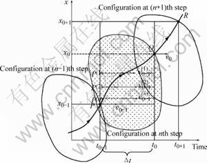
Fig.1 Concept of backward tracing simulation and update of configuration during forward loading and backward tracing
In backward tracing, the change of the geometrical configuration of a deforming body is represented as follows:
![]() (2)
(2)
where x0-1=x0-?t?v0-1. The geometrical configuration x0-1 at time t=t0-1{(n-1)th step} is achieved from the point Q. Therefore, the problem is to determine the velocity field v0-1, based on the information of the geometrical configuration x0 at time t=t0.
As shown in Fig.1, the solution of one step during backward tracing is as follows.
1) Take v0, x0 at Q(t=t0).
2) Set i=1.
3) While i��N do steps (1)-(6);
(1) Set P(i)=x0-v0??t;
(2) Calculate ![]() at
at![]()
(3) Set ![]()
(4) If ![]() , then
, then
OUTPUT (current step at ![]() completed successfully)
completed successfully)
Go to previous time step at ![]()
(5) Set ![]() (Update
(Update![]() )
)
(6) Set ![]()
4) OUTPUT (procedure completed unsuccessfully) STOP
where![]() is the maximum number of iteration and TOL is a tolerance.
is the maximum number of iteration and TOL is a tolerance.
2.2 Key technologies in 3D backward tracing scheme of blade precision forging
2.2.1 Initial velocity field
The blade precision forging is usually a hot forming process which depends on the strain-rate significantly, but the effect of material strain harden is not significant during the process, so the rigid-viscoplastic material model without material strain harden is adopted. Thus, the generation of the initial velocity field of backward tracing simulation does not depend on the history of deformation and the detailed generation steps are as follows.
1) The normal velocity of boundary nodes contacting with dies is obtained by means of the velocities of dies.
2) Regard the results of step 1) as an input condition, a velocity field is generated by combining the direct iterative method with Newton-Raphson iterative method;
3) The initial velocity field of backward tracing simulation is achieved by reversing the direction of the velocity field achieved in step 2).
2.2.2 Criterion of separating node from dies
The boundary conditions for non-steady state forming processes change during forward loading and the way by which this change occurs depends on the preform shapes. It is not difficult to see that different preform shapes can be obtained by imposing different dynamic boundary conditions in backward tracing simulation. Dynamic boundary conditions are controlled by altering the time and sequence of separating a node from dies. However, it is difficult to obtain proper alteration to the separating time and sequence due to the complicated shape of blade in the backward tracing simulation. In this paper, a new method, namely the tracking-fitting-revising method[16], is proposed, which can be used to determinate the criterion of separating a node from die in the backward tracing simulation. The detailed steps of the new method are as follows.
1) The single stage forging process of blade is tracked, and the time and coordinates of boundary nodes touching die are recorded;
2) A relationship between touching time and coordinates of touching nodes is fitted;
3) The relationship obtained by step 2) is revised to make the boundary nodes of touching die to be separated simultaneity from two edges of die during the backward tracing simulation.
2.2.3 Ceasing criterion
A series of intermediate configuration which can be used as preform shape are obtained in backward tracing simulation. Nevertheless, the blade precision forging belongs to hot forming process, and the heat exchange between the workpiece and die surfaces may do harm to the surface quality and inner microstructure distribution. In order to decrease the heat transfer between the workpiece and die surfaces, the contacting area between the preformed billet and die surface should be as little as possible at the beginning of the precision forging process, so the ceasing criterion of the backward tracing simulation is that all the boundary nodes are detached from dies.
2.3 Backward tracing simulation system
In this paper, the 3D backward tracing simulation system has been developed in terms of the structured programming method. This system is modified from the previous rigid-viscoplastic FEM program 3D-PFS[17], and is added several subroutines for backward tracing and solving of the key technologies. This system can be applied to preform design of the blade precision forging processes and other complicated massive deformation process.
3 Results and discussion
3.1 Simulation conditions and mechanical model
The material of the workpiece used in the simulation is Ti6Al4V, and the stress-strain rate relationship (measured in MPa) at the working temperature of 950�� is as follows[18]:
![]() (3)
(3)
The velocity of upper die is taken to be 20mm/s and the lower die is still. There exist neural-velocity points during the blade precision forging process, so the friction model of an arctangent function is adopted, which can be expressed as[19]
![]() (4)
(4)
where m is the friction factor as 0.2, k is the yield shear stress, us is the velocity vector of the workpiece relative to the die, u0 is a very small positive number compared to us, and t is the unit vector in the direction of us.
The work environment of blade body, the key part of blade, is severe, so the blade body is taken as object. Fig.2(a) shows the initial finite element mesh system of the blade body, including 364 hexahedral isoparameteric elements with eight-node and 536 nodes totally. Fig.2(b) shows the mesh system of the upper and lower dies used in simulation. In each die, 434 rigid triangular elements and 256 nodes are included. During the blade precision forging process, the tenon and the integral tip shroud prevent the material flowing along the axial direction, so an axial displacement constrain is applied to the end faces of the blade body in order to hold back the material from flowing along axial direction.
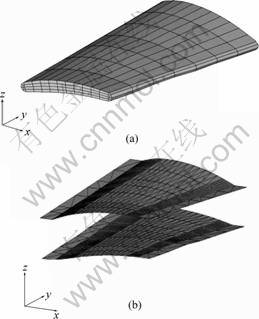
Fig.2 Meshes of blade body and dies: (a) Initial meshes of blade body; (b) Upper and lower dies
3.2 Results and discussion
Before backward tracing simulation, it would be helpful if some knowledge on metal flow involved in forging. Thus, forward loading simulation of the single stage forging process of blade is performed. Fig.3 shows the deformed meshes of this simulation, where the original billet is a round bar calculated by constancy of volume and both the two ends�� radii of the bar are almost the same. From Fig.3, it is visible that the outlet edge is unfilled, whereas small flash occurs on the inlet edge. Moreover, workpiece nearly reaches the limited workability of material in this process. Hence, preform design requires for the blade precision forging.
Taking the forward loading simulation as reference object, as shown in Fig.3, the time and sequence of separating a node from dies are obtained by using the tracking-fitting-revising method. For the blade precision forging, the final product is obtained from a preform billet which is achieved from the original billet. Because of this feature and the limited workability of material, the precision forging time of the final stage is shorter than the single-stage precision forging. In this paper, the separating time obtained above is decreased by 2/3 by the experiences.
By applying above separating time and sequence to the 3D backward tracing simulation system, the deformed meshes of the backward tracing simulation and the shape of preformed billet can be obtained, as shown in Fig.4. It is evident that the preform shape is simple and may be used in the manufacture.
In order to verify the validity of the backward tracing simulation results, it needs forward loading simulation for preformed billet above. The procedure using software DEFORM-3D is shown in Fig.5. It can be
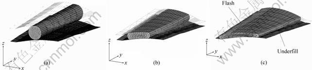
Fig.3 Deformed meshes of forward loading simulation using original billet
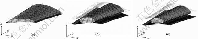
Fig.4 Deformed meshes of backward tracing simulation
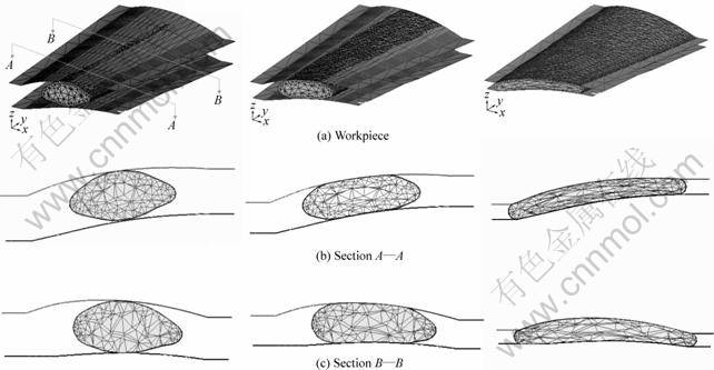
Fig.5 Deformed meshes of workpiece and typical sections in verifying simulation
seen that the die cavity is completely filled without formation of defects such as flash and overlap, and the desired shape reaches at the end of the process. Thus, the preform design satisfies the requirement of the blade precision forging.
4 Conclusions
1) The key technologies of backward tracing scheme based on 3D rigid-viscoplastic FEM are studied, and some valid algorithms or methods are proposed. A velocity field is generated by combining the direct iterative method with Newton-Raphson iterative method, and then the initial velocity field of backward tracing simulation is achieved by reversing the direction of the velocity field. The tracking-fitting-revising method is proposed and can be used to determinate the criterion of separating a node from die in the backward tracing simulation. The ceasing criterion of the backward tracing simulation is that all the boundary nodes are separated from die.
2) The 3D backward tracing simulation system has been developed, which can be applied to preform design of the blade precision forging processes and other complicated massive deformation process.
3) The preformed billet is obtained, which ensures the die cavity being completely filled without formation of defects.
References[1] LIU Yu-li. 3-D FEM Analysis of Forming Laws in Precision Forging Process of Blade [D]. Xi��an: Northwestern Polytechnical University, 2001. (in Chinese)
[2] ZHAN Mei, LIU Yu-li, YANG He. Influence of shape and position of the preform in the precision forging of a compressor blade [J]. Journal of Materials Processing Technology, 2002, 120(1-3): 80-83.
[3] ZHAO G Q, WRIGHT E, GRANDHI R V. Sensitivity analysis based preform die shape design using the finite element method [J]. International Journal of Machine Tools and Manufacture, 1997, 37(9): 1251-1271.
[4] ZHAO Xin-hai, ZHAO Guo-qun, WANG Guang-chun, et al. Preform die shape design for uniformity of deformation in forging based on preform sensitivity analysis[J]. Journal of Materials Processing Technology, 2002, 128(1-3): 25-32.
[5] ZHAO Guo-qun, MA Xin-wu, ZHAO Xin-hai, et al. Studies on optimization of metal forming processes using sensitivity analysis methods[J]. Journal of Materials Processing Technology, 2004, 147(2): 217-228.
[6] ACHARJEE S, ZABARAS N. The continuum sensitivity method for the computational design of three-dimensional deformation processes [J]. Computer Methods in Applied Mechanics and Engineering, 2006, 5: 1-21.
[7] PARK J J, REBELO N, KOBAYASHI S. A new approach to preform design in metal forming with the finite element method [J]. International Journal of Machine Tool Design and Research, 1983, 23(1): 71-79.
[8] WANG zhen, XUE Ke-min, LIU Ying-wei, et al. The application of UBET in backward tracing simulation of a blade [J]. Journal of Harbin Institute of Technology, 1996, 3(1): 78-82. (in Chinese)
[9] XUE Ke-min, LIU Ying-wei, WANG Zhen, et al. Solution of key problems in UBET backward tracing simulation of a blade [J]. Acta Metallurgica Sinaca, 1997, 33(10): 1115-1120. (in Chinese)
[10] WANG Zhen, XUE Ke-min, LIU Ying-wei. Backward UBET simulation of the forging of a blade [J]. Journal of Materials Processing Technology, 1997, 65: 18-21.
[11] KANG B S, KIM N S, KOBAYASHI S. Computer-aided preform design in forging of an airfoil section blade [J]. International Journal of Machine Tools and Manufacture, 1990, 30(1): 43-52.
[12] KANG B S, KOBAYASHI S. Preform design in ring rolling processes by the three-dimensional finite element method [J]. International Journal of Machine Tools and Manufacture, 1991, 31(1): 139-151.
[13] KU T W, LIM H J, CHOI H H, et al. Implementation of backward tracing scheme of the FEM to blank design in sheet metal forming[J]. Journal of Materials Processing Technology, 2001, 111: 90-97.
[14] KIM J, KANG B S. Implementation of backward tracing scheme of the FEM for design of initial tubular blank in hydroforming [J]. Journal of Materials Processing Technology, 2002, 125-126: 839-848.
[15] KIM J, KANG B S, HWANG S M. Preform design in hydroforming by the three-dimensional backward tracing scheme of the FEM [J]. Journal of Materials Processing Technology, 2002, 130-131: 100-106.
[16] ZHANG Jian-she, LIU Yu-li, YANG He, et al. The determination of node releasing criterion in three dimensional finite element backward of bade precision forging [J]. Heavy Machinery, 2006, (2): 18-23. (in Chinese)
[17] ZHAN Mei. Research on Three-dimensional FEM Numerical Simulation of Precision Forging For blade with a Damper Platform [D]. Xi��an: Northwestern Polytechnical University, 2000. (in Chinese)
[18] Altan T. Modern Forging-equipment, Materials and Process [M]. LU Suo transl. Beijing: Defence Industral Press, 1982. 150. (in Chinese)
[19] LIU Yu-li, YANG He, ZHAN Mei, et al. A study of the influence of the friction conditions on the forging process of a blade with a tenon [J]. Journal of Materials Processing Technology, 2002, 123(1): 42-46.
Foundation item: Project(50225518) supported by the National Science Foundation of China for Distinguished Young Scholars��Project(02H53061) supported by the Aeronautical Science Foundation of China; Project(05-1) supported by the Foundation of State Key Laboratory of Plastic Forming Simulation and Mould Technology
Corresponding author: YANG He; Tel/Fax: +86-29-88495632; E-mail: yanghe@nwpu.edu.cn
