

Microstructures of surface modification layer on Q235 steelproduced by laser melt injection of WC
LI Fu-quan(�Ȫ), CHEN Yan-bin(�����), LI Li-qun(����Ⱥ)
State Key Laboratory of Advanced Welding Production Technology,
Harbin Institute of Technology, Harbin 150001, China
Received 10 August 2009; accepted 15 September 2009
Abstract:
WC powder was injected onto the surface of Q235 steel by laser melt injection (LMI). The influence of process parameters was studied. The microstructure and composition of the coatings were analyzed by SEM, XRD and EDS. The hardness and wear-resistant property of the coatings and Q235 steel were measured. The results show that LMI layer can be achieved only under the condition that process parameters meet the strict requirements. By optimizing the process parameter, excellent coatings can be acquired by injecting WC powder onto the surface of Q235 steel. The microstructure in the coatings is complex, which consists of WC, W2C and M6C(Fe3W3C-Fe4W2C) phases. The difference of Fe3W3C microstructure in different zones of the coatings is obvious. Both the compositions of the reaction layers around the particle and dendrite precipitation carbides in the upper coating are Fe3W3C. The average hardness of LMI layer is above HV 900, which is about four times that of Q235 steel. The friction coefficient of LMI layer is only one quarter that of the substrate, which indicates that the wear resistance of the coatings is enhanced sharply.
Key words:
laser melt injection(LMI); WC; surface modification layer; wear-resistant property;
1 Introduction
Laser surface processing is appropriate to improve the surface property of metal. Previous studies[1-2] showed that laser cladding is an efficient and cost-effective technique to improve the surface properties with the ability of significantly extending the performance of the material as a whole. However, two major problems in laser cladding coating are usually observed, namely, the cracking of the cladding coating and the dissolution of the reinforced particles[3-4]. In laser cladding, only a thin layer of the substrate melts together with the additive material to form a MMCs coating. The sharp interface between the coating and the substrate is usually the potential source of cracks. In addition, the direct irradiation of the laser beam to particles promotes their dissolution, which results in excessive intermetallic compounds and thick reaction layers in the composites layer.
As an extension of laser cladding, laser melt injection(LMI) technology has great potential in the field of material surface modification. LMI was studied firstly by AYERS et al[5-7]. In recent years, with the development of laser surface process and synchronized powder feeding, great progresses in LMI has been made and many kinds of particles reinforced MMCs were produced[8-9]. In the LMI process, a high power laser locally melts the top part of a metal substrate. At the same time, a powder is injected into the melt pool. Because of limited interaction with the laser beam, the particles injected is still in a solid state. After rapid solidification of the melt pool, the particles are trapped in the top layer of the substrate. It is quite similar to the side laser cladding and all parameters in these two techniques are similar[10-11]. However, the distinct difference of these two techniques is the processing object of the laser beam. The main processing object of side laser cladding is the additive powder, while for LMI the substrate is the processing object. In LMI, the usual interfacial problems between the coating and the substrate in laser cladding are solved, because the additive powder is injected into the melt pool of the substrate directly. Consequently, there is no sharp compositional change across the interface of the MMCs layer and the substrate. Unlike laser cladding, the contact between the laser beam and particles is limited to the level that is just necessary to form strong bonding interface. The excessive dissolution of the reinforcement particles is avoided because the particles are injected into the melt pool of the substrate
directly. Due to above characteristic, LMI is exceedingly suitable for the preparation of a thin metal-matrix composite (MMC) layer on the surface of metal[12-13].
However, previous research in LMI has mainly concentrated on the high specific strength materials such as titanium alloy and aluminium alloy[14-15]. Few works chose steel as substrate to produce surface modification layer for improving the mechanical and tribological properties. In this work, WC powders were injected onto the surface of Q235 steel by LMI process. The influence of process parameters on the form of LMI coatings were studied. The microstructure and composition of the coatings were analyzed. The wear-resistant property of the coatings and Q235 steel was investigated comparatively.
2 Experimental
Q235 steel with dimensions of 200 mm��40 mm��5 mm was used as substrate. Before LMI treatment, the surface of the sample was cleaned with acetone. Casting WC powder with mean size of about 80 ��m was used as the injection particle. The LMI experiment was carried out with a DL-HL-T5000 5 kW continuous CO2 laser. The powder was supplied with a PEL-1A powder feeder and the movement of the specimen was controlled by a four-axis computer numerically controlled (CNC) table.
During the LMI process, the laser beam was defocused to a spot size of 3.5 mm at the substrate surface. In order to avoid excessive dissolution of WC, the focus point was set below the substrate surface. The carrier gas (argon, 1.5 L/min) transported the WC powder into the nozzle, where most gas escaped through the upper outlet, and the powder was injected into the melt pool. WC was injected into the back part of the melt pool at an angle of 35�� with respect to the surface normal, which can avoid excessive interaction between the particles and laser beam. In addition, a coaxial shielding gas (argon, 5 L/min) supplied by the special powder nozzle was applied on the sample, which can prevent the specimen from oxidation and focus the powder stream. The microstructures of LMI layer were analyzed by HITACHI S4700 FEI Quanta 200 scanning electron microscope (SEM) equipped with an energy dispersive spectroscope (EDS). The phase structure was identified by X-ray diffractometry (XRD). Hardness and wear- resistant property of the LMI layer and Q235 steel was measured, respectively.
3 Results and discussion
3.1 Laser melt injection process
The positioning of the powder flow during laser melt injection can be divided into pre-feeding mode and back-feeding mode. The powder feeding nozzle was aligned at the center of the laser beam, which was named as pre-feeding mode. The powder feeding nozzle was aligned at the back of the laser beam, which was named as back-feeding mode. Under the condition of laser power density P=300 W/mm2, scanning speed v=0.4 m/min and powder feeding rate vp=105 mg/s, Fig.1 shows the cross section micrographs of LMI layer under the condition of pre-feeding mode and back-feeding mode respectively. The angle of powder feeding was set at 50? and 135? respectively for Fig.1(a) and Fig.1(b). As shown in Fig.1(a), in pre-feeding mode, it can be found that most of the WC powders dissolve in the melt pool, little powder leaves in the LMI layer. There is distinctive difference under the condition of back-feeding. As shown in Fig.1(b), more powder particles can be found in the LMI layer. This can be attributed to the high rate of absorption of powder to the laser energy. Under the condition of pre-feeding mode, most of WC powder was subjected to laser irradiation directly, especially some of the WC powder move cross the center of the laser beam. The longer retention time of particles in the melt pool and higher temperature of laser beam lead to the melting of most part of WC particles. The liquid WC comes into melt pool and reacts with liquid Fe. Just because of full reaction between particles and substrate, the pre-feeding mode was widely used in laser cladding. On the contrary, under the condition of back-feeding, particles even do not cross the laser beam, most of the particles move into the back part of melt pool. This can avoid laser beam irradiation to some extent. At the same time, this also leads to the retention time of particles in the melt pool decrease distinctively. Due to the above factors, the degree of reaction between the particles and melt pool decreases distinctively. Just as shown in Fig.1 (b), sufficient WC particles remain in LMI layer. These WC particles become reinforcement phase in the substrate. Based on the above investigation, the back-feeding is more suitable to laser melt injection and is selected in our experiment.
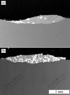
Fig.1 Cross section micrographs of LMI layer by different powder feeding modes: (a) Pre-feeding mode; (b) Back-feeding mode
Under the condition of laser power density P=300 W/mm2 and powder feeding rate vp=135mg/s, Fig.2 shows the influence of laser scanning speed on the morphology of LMI layer. As shown in Fig.2, it can be found that scanning speed has great influence on the penetration of LMI layer. The penetration of LMI layer decreases with increasing scanning speed. This is due to that the scanning speed is related to the heat input of laser beam. The increment of scanning speed leads to the reduction of heat input of laser. Consequently, the penetration of LMI layer decreases.
In the LMI process, several parameters, both for laser and powder flow, have influence on the surface modification coating. In many cases the parameters are not independence. This makes it rather difficult to
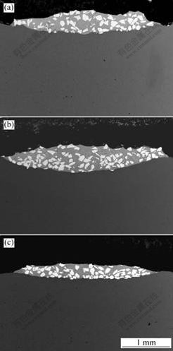
Fig.2 SEM images of LMI layer at different scanning rates: (a) v=0.3 m/min; (b) v=0.5 m/min; (c) v=0.7 m/min
optimize each individual process parameter. After systematic experiments, suitable processing parameters are obtained as follows: laser power density P=300 W/mm2��scanning speed v=0.3-0.6 m/min, powder feeding rate vp=80-135 mg/s, powder feeding angle ��=50?-60?, flux of carrier gas vf=450 L/h. Under the optimized parameters, the cross section morphology of LMI layer is shown in Fig.3. It can be observed that the LMI layer is free of defects, and WC particles distribute in the LMI layer. With the increment of depth of LMI layer, the volume fraction of WC in the matrix increases. At the middle part of LMI layer, the volume fraction of WC in matrix reaches the peak value. Most of WC particles remain in original shape, which indicates that the melting loss of WC particle is reduced during LMI process.
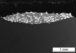
Fig.3 Cross section morphology of LMI layer under condition of optimized parameter
3.2 Microstructure of LMI layer
The microstructure of LMI layer is complicated due to the reaction between WC particles and melt pool. Under the condition of optimized parameters, the phase structure in the LMI layer was analyzed using XRD. As shown in Fig.4, the XRD result reveals that M6C (Fe3W3C-Fe4W2C) and Fe3C phases are identified besides the original ��-Fe, WC and W2C phases.
The microstructure of the matrix between the injected particles is quite complicated and can roughly be divided into there regions: the top part, center part and bottom part of LMI layer. The differences of microstructure in different zones of the LMI layer are obvious.
The microstructure at the top part of the LMI layer is shown in Fig.5(a). It can be found that, around WC particle, the matrix precipitates a large amount of dendrite primary crystal and irregular strand eutectic crystal. After composition analysis by EDX, the related EDX quantitative-analysis results of primary and eutectic microstructure indicate that the mole fractions of W and Fe are approximately the same. Referring to XRD results, it can be deduced that the phase structure of crystal is Fe3W3C. In the top part of the LMI layer, due to the higher temperature and the longer retention of the melt
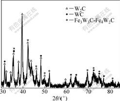
Fig.4 XRD spectrum of LMI layer
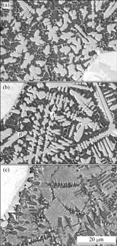
Fig.5 SEM images of substrate microstructures at different locations of LMI layer(P=300 W/mm2, v=0.4 m/min, vp=135 mg/s): (a) Top part; (b) Center part; (c) Bottom part
pool, WC particle is heated to higher temperature and dissolves partially. WC is decomposed into W and C, which reacts with Fe and forms block primary. On the other hand, the surfaces of WC particles will melt when they are heated by laser beam. After injected into the laser pool, liquid WC droplets which break away from WC particles will decompose into W and C atoms. They react with Fe atoms and form crystal nucleus in the liquid pool. The left W and C is small drop, locating far away from the WC particle, which react with melt pool and form irregular strand Fe3W3C. During the solidification of laser pool, kinds of strand eutectic precipitation carbides Fe3W3C are formed in the upper coating. The liquid WC droplets that adhere to the surfaces of WC particles will also decompose into W and C atoms. This leads to W-rich zone around WC particles. W reacts with Fe atoms in W-rich zone. Dendrite Fe3W3C primary clinging to WC particles grows up.
It can be seen in Fig.5(b) that, the microstructure precipitated at the centre part of LMI layer is complex, mainly including dendrite, columnar and block crystals. Compared with the top part of LMI layer, more fishbone-like eutectics form. EDX analysis results of dendrite crystals (A point in Fig.5(b)) is as follows(mole fraction): 23.63%W��27.36%Fe��49.01%C. Referring to XRD results, it can be deduced that the phase structure of dendrite is Fe3W3C. EDX analysis results of block crystals (B point in Fig 5.(b)) is as follow(mole fraction): 12.57%W��24.21%Fe��63.21%C. Referring to XRD results, it can be deduced that the phase structure of this block M6C precipitation is Fe4W2C. The complexity of microstructure at the center part of LMI layer is determined by the composition and cooling condition of melt pool. Compared with the top part of LMI layer, the temperature of melt pool at the centre part is lower and time-span of solidification is shorter. The convection and agitate effect in the melt pool is not sufficient. The composition of melt pool is inhomogeneous and this leads to the inhomogeneous microstructure.
At the bottom part of LMI layer, around WC particles, it cannot find primary crystal, instead of formation a large mount of tiny fishbone-like eutectic. Due to the cooling effect of substrate, the temperature at the bottom of LMI layer is low and at just about the liquidus temperature. At this temperature, primary crystal can not precipitate and mainly form eutectic structure. EDX analysis results of tiny fishbone like microstructure is as follows(mole fraction): 26.97%W, 26.63%Fe, 46.40%C. Referring to XRD results, it can be deduced that the phase structure of dendrite is Fe3W3C.
3.3 Wear-resistant property of LMI layer
The hardness profile of LMI layer and substrate is shown in Fig.6. The hardness of LMI layer is higher than that of substrate and heat-affected zone(HAZ). The microhardness of the LMI layer fluctuates from HV850 to HV1 000, with the average hardness of HV900. The microhardness of substrate is about HV240. It can be found that the hardness of LMI layer is about four times that of Q235 steel. The hardness of the LMI layer fluctuates in a wide range. This can be explained by the inhomogeneous structure in the LMI layer. There are WC particles, ��-Fe, Fe3C and M6C phases. Due to the effect of strengthening, the area of indentation locates at different positions of the matrix, and the hardness will change distinctively. WC particles and M6C dendrite has strengthening effect on the matrix. Sometimes it is so difficult to avoid making indentations close to the high hardness WC particles (HV1 500-2 200) that the hardness value is rather high. The hardness curve fluctuates at some areas despite an average of three measurements has been taken.
The friction curve of LMI sample and untreated Q235 steel is shown in Fig.7. It can be seen that the friction coefficient of the untreated sample rises up to 0.9 rapidly. There is no smooth stage in abrasion. The abrasion results show that the friction coefficient of LMI layer keeps around 0.2 in the primal 400 s, and then rise up slowly to 0.6 until 1 000 s. The results show that the wear resistance of coatings enhances sharply comparing with Q235 steel substrate. The granule abrasion dominates the abrasion process of coatings, while the adhesive abrasion is the primary abrasion mechanism of Q235 steel. The good performance of coatings is not only due to high hardness of WC particles, but also thanks to the peculiar studdeding structure. WC particles play a role as frameworks, which endure load as well as decrease the abrasion of coating. Meanwhile, dendrite precipitation carbide of M6C has nail fixing effect and strengthens the coating substrate, so that the coating substrate could support WC particles more tightly.
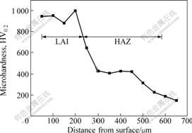
Fig.6 Hardness profile of LMI layer and heat affected zone
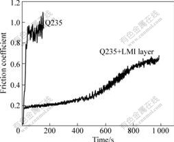
Fig.7 Friction curve of LMI sample and untreated Q235 steel (n=300 r/min, r=1.5 mm)
4 Conclusions
1) LMI layer can be achieved only under the condition that process parameters meet the strict requirements. The optimized processing parameters are obtained as follows: laser power density P=300 W/mm2��scanning speed v=0.3-0.6 m/min, powder feeding rate vp=80-135 mg/s, powder feeding angle ��=50?-60?, flux of carrier gas vf=450 L/h.
2) The LMI layer consists of WC, W2C, and M6C (Fe3W3C-Fe4W2C) phases. The differences of the M6C phase in the top part, the centre part and the bottom part of LMI layer are obvious. This can be explained by the different composition and cooling conditions at the different part of melt pool.
3) The average hardness of LMI layer is above HV900, which is about four times that of substrate. The friction coefficient of LMI layer is only one quarter that of the substrate, which indicates that the wear resistance of LMI layer is enhanced sharply.
References
[1] ZENG X Y, TAO Z Y, ZHU B D, ZHOU E H, CUI K. Investigation of laser cladding ceramic-metal composite coatings: Processing modes and mechanisms [J]. Surface and Coatings Technology, 1996, 79: 209-217.
[2] TONDU J S, SCHNICK T, PAWLOWSKI L. Laser glazing of FeCr-TiC composite coatings [J]. Surface and Coatings Technology, 2000, 123: 247-251.
[3] CHEN Y, WANG H M. Growth morphologies and mechanism of TiC in the laser surface alloyed coating on the substrate of TiAl intermetallics [J]. Journal of Alloy and Compounds, 2003, 351: 304-308.
[4] WU X L, CHEN G N. Microstructure characterization and evolution of laser cladding Fe-based alloys [J]. Acta Metallurgica Sinica, 1998, 34(10): 1033-1038.
[5] AYERS J D. Modification of metal surface by the laser metal-particle injection process [J]. Thin Solid Films, 1981, 84: 323-331.
[6] AYERS J D. Wear behavior of carbide-injected titanium and aluminum alloys [J]. Wear, 1984, 97: 249-266.
[7] AYERS J D, TUCKER T R. Particulate-TiC-hardened steel surfaces by laser melt injection [J]. Thin Solid Films, 1980, 73(1): 201-207.
[8] PEI Y T, OCELIK V, HOSSON J T M D. SiCp/Ti6A14V functionally graded materials produced by laser melt injection [J]. Acta Materialia, 2002, 50: 2035-2051.
[9] VREELING J A, OCELIK V, PEI Y T, VAN AGTERVELD D T L, HOSSON J T M D. Laser melt injection in aluminum alloys: on the role of the oxide skin [J]. Acta Materialia,2000, 48: 4225-4233.
[10] OCELIK J A, HOSSON J T M D. Ti-6Al-4V strenghened by laser melt injection of WCp particles [J]. Acta Materialia, 2002, 50: 4913-4924.
[11] YUE T M, WU Y X, MAN H C. Laser surface treatment of aluminium 6013/SiCp composite for corrosion resistance enhancement [J]. Surface and Coatings Technology, 1999, 114: 13-18.
[12] KLOOSTERMAN A B, KOOLI B J, HOSSON J T M D. Electron microscopy of reaction layers between SiC and Ti-6A1-4V after laser embedding [J]. Acta Materialia, 1998, 46(17): 6205-6217.
[13] HOSSON J T M D, OCELIK V. Fuctionally gated materials produced by high power lasers [J]. Materials Science Forum, 2003, 426/432: 123-130
[14] CHEN Y B, LIU D J, LI F Q, LI L Q. WCp/Ti-6Al-4V graded metal matrix composites layer produced by laser melt injection [J]. Surface & Coating Technology, 2008, 202: 4880-4887.
[15] OCELIK V, VREELING J A, HOSSON J T M D. EBSP study of reaction zone in SiC/Al metal matrix composite prepared by laser melt injection [J]. Journal of Materials Science, 2001, 36: 4845-4849.
(Edited by LONG Huai-zhong)
Corresponding author: Li Fu-quan; Tel:+86-451-86415506; E-mail:lifuquan@hit.edu.cn
