
J. Cent. South Univ. (2012) 19: 553-561
DOI: 10.1007/s11771-012-1039-9![]()
Numerical evaluation of uplifting effect for upper structure by grouting
ZHANG Min(����), WANG Xing-hua(���ǻ�), WANG You(����)
School of Civil Engineering, Central South University, Changsha 410075, China
? Central South University Press and Springer-Verlag Berlin Heidelberg 2012
Abstract:
A stratum grouting-soil-structure interaction model which simplified the grouted zone into a series of spherical grout bulbs was established using FLAC3D program. The hypothetical non-uniform expansion process to reach an assigned volume strain due to soil compression by grouting was achieved by imposing radial velocity on outer mesh nodes of these spheres. This new method avoids the repeated trial calculation needed in the traditional method which applied a fictitious expanding pressure in the grouting element. The deformation and additional internal forces of structure were investigated during each grouting strategy and the influences of various stiffness of grouting proof curtain and bearing capacity of pile tip were discussed simultaneously. The numerical model is proved to be effective to replicate general behavior expected in the field and is capable of modeling the uplifting effect for the surface structure by grouting.
Key words:
grouting; ground uplifting; soil-structure interaction; numerical simulation��
1 Introduction
Adopting compaction grouting or fracturing grouting under the foundation is demonstrated to be an effective way to control and offset subsidence for tilted buildings, and has been widely used in the field of jack lifting. The basic principle is to inject grout into the zone at high pressures to compensate the ground loss and stress relief induced by deep excavations or tunneling in the immediate vicinity of existing buildings. Several cases of successfully controlling foundation settlement and lifting and re-leveling settled structures were reported by some researchers [1-3].
In strict sense, building uplifting by grouting is a challenging technique which involves a set of complex soil parameters as well as grouting variables, e.g., grouting pressure, grouting stage length, injection rate, limiting injection pressure, injection pipe layout. A successful heave of building should be on the premise of compensation grouting, grouting wall completion and ground improvement and only the repeated, multi-pointed and un-dissipated ground grouting could achieve safe and effective building lifting [4]. The grouting compensation efficiency is also affected by excess pore water pressure on the thick soft clay deposit and may be a negative value, i.e. the upward displacement is offset by the consolidation settlement [5]. Several analytical models such as the conical shear failure model and inclined compaction grouting model have been developed to investigate the mechanism for structural uplifting based on various hypotheses [6-9]. By applying an internal pressure to zero-thickness interface elements embedded in mesh, WISSER [10] simulated the compaction grouting with finite-element analysis to arrest foundation settlement caused by tunneling.
At present, researches in the area of uplifting effect using numerical simulation are generally based on either the use of a prescribed strain approach to model grout injection or, alternatively, a prescribed pressure approach. In the prescribed strain approach, grout injection is simulated by imposing appropriate values of strain on the elements representing the grouted soil [11-13]. In the prescribed pressure approach, the injection process is simulated by the application of fictitious internal pressure to the grouting elements. After injection is complete, the stiffness of these elements is increased to an appropriate value [10, 14-15]. However, in order to reach the required volume strain for grout bulb, it needs a series of trial calculations through adjusting the magnitude of pressure, which will cost much time and affect the efficiency, especially for complicated models. Therefore, the prescribed strain approach is adopted in the analyses of this work.
To simulate the expansion procedure by grouting in FLAC3D, an assigned radial velocity is exerted on the nodes of outer face of grout bulb and the number of run-steps can be determined forehand to avoid the trial calculation. With the method, node velocity of various magnitudes and directions can be assigned to the specified region to achieve isotropic or anisotropic expansion such as the cases of spherical, ellipsoidal or cylindrical grouted zone, together with the fracture grouting where the slurry extends along a specified direction.
During the process of heaving, the soil expansion by grouting causes the foundation movement primarily and then brings about upward displacement and additional internal forces in the existing structure. The weight and stiffness of the building in turn affect the movement of the ground. So, the significant influence of the stratum grouting-soil-structure interaction on the heaving of the building is worth concerning. In this work, the grouting strategies to heave the inclined skirt building were studied using a full three-dimensional finite difference analysis (FDM) which simplified the grouted zone into a series of spherical grout bulbs. The heave and internal forces in different stages as well as the influence of stiffness of grouting proof curtain and bearing capacity of pile tip were discussed herein.
2 Description of heaving scheme
During the excavation of a metro station in Guangzhou, large quantities of underground water were lowering and lost. Subsequently, an adjacent four-story reinforced concrete skirt building, which was founded on pile foundation with depth of 6 m, suffered a subsidence of 96.4 mm on the east side and 22.2 mm on the west side. The maximum settlement exceeded the limit value of 30 mm, and obvious crack and deformation were found at the settlement joint. According to the site investigation report, the subsurface condition and relevant geotechnical parameters of the soil layers at the site are summarized in Table 1, and the shear strength c��, undrained friction ��' and compression modulus Es were determined from undrained test results.
According to the reinforcement scheme for the building, the technology of tracing compensation grouting with sleeve-valve-pipe was carried out to recover the settlement due to groundwater lowering. The grouted zone was located in pile bearing layer to avoid the possible damage of floor slabs due to shallow grouting. The layout of grouting holes is shown in Fig. 1. According to the sequence of the grouting, a grouting-proof curtain with depth of 45 m and width of 1 m was constructed ahead of heaving, and subvertical jet grouted columns along the axis were driven simultaneously in the order of Axis 13 to 9. All the depths of grout holes were 35 m except the ones with depth of 50 m at both corners of Axis 13.
In grouting, the cement-sodium silicate slurry with a volume ratio of 1:(0.5-0.7) of grout to sodium silicate of Baum 30-40 as well as the 42.5 Portland cement with a water cement ratio of 0.6-1 were selected. Additionally, the sleeve grout mixture mainly consists of 10% cement, 20%-25% (mass fraction) bentonite and sufficient water to provide proper slump.
During the both compaction grouting and lifting grouting operations, pre-buried PVC pipes were used for the grout pipes with a nominal diameter of 110 mm and grout hoses equipped with a double packer were inserted into the grout pipe. The packer sealed the grout pipe on either sides of a rubber sleeve, which allowed the grouting of each single rubber sleeve along the section to be treated. The grouting pressure used in compaction stage ranged from 0.3 to 0.6 MPa. At the later stage, the grout was pumped at a relatively high value between 2 and 3 MPa to fracture the ground. Due to relatively larger settlement in the area near Axis 13, the grouting pressure could be properly raised during the injection. The compaction was applied in stages beginning at the bottom of drilled shaft and working upward through the ground.
To alleviate the building settlement rate and avoid the structure damage resulted from differential subsidence, it is required to continuously monitor the vertical movement during the grouting operation. Once the settlement rate in some regions was found to be large, a repeated grouting reinforcement would be carried out and some grouting parameters together with the grouting process may need adjustment correspondingly. As the building deformation achieves either of the two following criteria: 1) the settlement rate reaches 2-3 mm/d, and 2) the maximum differential subsidence exceeds 8 mm/10 m, the dynamic tracking and retrieving grouting usually begin to be implemented.
Table 1 Soil properties used in analysis

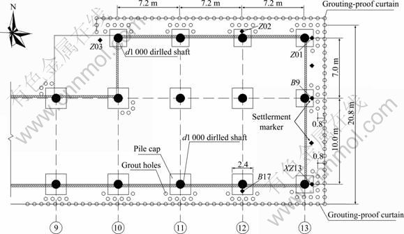
Fig. 1 Layout of grout holes
The terminal criteria of grouting at each stage are determined by the grouting pressure or grout quantity. When the injected grout volume reaches 200-300 L/m or the final grouting pressure exceeds 1.0 MPa, the grouting can be stopped for next stage. Besides, once the grout overflows and channeling appears, it should also suspend grouting and conduct complementary grouting after the grout solidification.
The building settlements of some measurement points located on the upper structure were monitored during the excavation. The location of the points in the vicinity of the excavation is reported in Fig. 1 and Fig. 2 shows the evolution of the surface settlements and heaves from August 2008 to February 2009. The observations during construction indicate that the grouting process can effectively reduce settlement and lead to a major surface heave, about 9.5 cm upward for marker XZ13. A considerable heave appears in the location near Axis 13 and the marked difference between the measurement points depends on the distance from such axis. However, a slightly upward trend appears at the end of grouting, in which the large-scale, stable, uniform and un-dissipated ground grouting is expected to achieve a safe and effective building lifting.
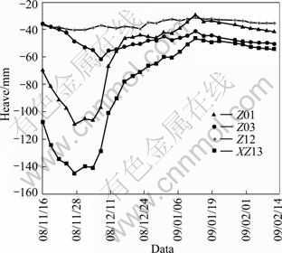
Fig. 2 Curves of in-situ building lifting deformation
3 Heaving mechanism with grouting
Normally, the building lifting can be divided into two stages: the first stage is to control and cut building subsidence, which can be regarded as a relative uplift; the second stage is the building lifting strictly. The first stage can be achieved with the dynamic tracking and retrieving grouting with the forms of grout penetration and pore filling. As the deep excavation and well-points dewatering would induce ground loss (such as soil loose, void or abscission layer), filling the pores of soil timely by injecting grout can greatly alleviate the ground settlement and is beneficial to the safety of building. The numerical analysis is usually used to estimate the location of the maximum displacement in order to limit further deformation development by compensation grouting. The building lifting in the second stage is mainly realized by means of soil compaction, consolidation and heave. As this lifting is often local, uneven, and even involves large displacement of ground, as shown in Fig. 2, it is crucially important to assess the stability of the structure and determine if or not its stability is affected by the grouting work.
The injected grout volume Qinj is the sum of the soil compression volume Qcom and the soil heaved volume Qsh, where the heaved volume can be attained by multiplying the uplifting displacement di of the observed point on surface and its corresponding area si, i.e. Qsh=��disi. Grouting efficiency �� is defined as
![]() (1)
(1)
where �� is not a constant and is influenced by soil characteristics, stress and consolidation history, and gradually decreases with time due to the soil consolidation. Sufficient related researches and experiences show that the value is generally 5%-20% [16].
The compaction grout bulb is simulated in this work as an expanding spherical cavity in an isotropic elasto-plastic continuum. As the densification and replacement affect the soil with compaction grouting, the pores of soil are assumed to be completely occupied by grout in the grouting zone. Two proposed deformation patterns of grout bulb, uniform and non-uniform expansion are shown in Fig. 3. In Fig. 3(a), radically uniformed expansion of ��R of the gout bulb is assumed to occur in all directions. However, as a matter of fact, the grouting pressure is not equivalent along various directions of the grout bulb. Consequently, the radial deformation is not uniform, as shown in Fig. 3(b). The boundary condition of the prescribed displacement for this case is illustrated as follows:
![]() (2)
(2)
where ur is the radial expansion deformation; �� is the angle of the calculated point to the horizontal; R is the diffusion radius of the slurry. It can be observed that the prescribed displacements are equal to 2?R at the crown and zero at the bottom of the grout bulb.
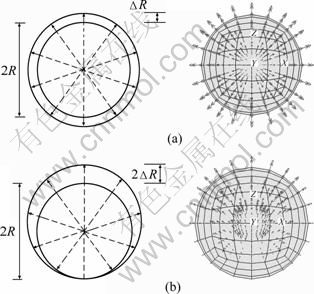
Fig. 3 Sketch of two deformation patterns of grout bulb: (a) Uniform expansion; (b) Non-uniform expansion
In order to compare the heave induced by both deformation patterns on the surface heave with different grouting depths, four groups of heave curves with H0=5 m, 8 m, 10 m and 15 m are illustrated in Fig. 4. The results with non-uniform expansion pattern, on the whole, are greater than the ones with uniform expansion pattern. The discrepancy of heaves attained by both models is apparent for shallow grouting and the curves appear narrow and deep. While for deep grouting, both methods give almost the same magnitudes of heave and the curves become wide and shallow. That is to say, the impact of self-deformation pattern of grout bulb on the heave is significant for relatively shallow grouting, and is worthy noticing for engineering utility.
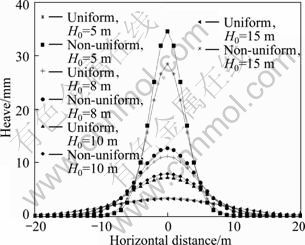
Fig.4 Influence of deformation patterns on heave
As previously mentioned, the grouting technique involves a series of unpredictable factors and the actual expansion patterns of the grout bulb should be diverse and vary considerably. The deformation assumptions shown in Fig. 3 are ideal situations and cannot perfectly represent all cases, but the non-uniform expansion model is no doubt a better choice compared with the traditional uniform expansion model.
4 Numerical model
In the view of the fact that the ground in the vicinity of Axis 13 is the key area to be heaved and in order to keep the run times to acceptable values, the overlying structure and the ground located in the area of Axes 12-13 are modeled using the finite difference program FLAC3D [17]. The actual spreading and hardening of the grouting mixture within the soil (e.g., CIVIDINI [18]) were not introduced in the calculations to simplify the problem. Figure 5(a) illustrates the finite difference mesh utilized in the analysis with overall sizes of -10��x��16.2, -9��y��26, -58��z��0, consisting of 15 772 brick elements and 15 714 nodes. At the bottom level of the computational domain, all movements are restrained; while at the lateral external sides, lateral movements perpendicular to the boundary are prohibited. The soils are assumed to be elasto-plastic and governed by Mohr-Coulomb constitutive model with an associated flow rule. And a linear elastic constitutive model is used for the grout bulbs and the grouting-proof curtain with compression modulus E=20 MPa and Poisson ratio ��=0.3. The pile and structure characteristics are given by: pile diameter D=1.0 m, pile length H=6 m, cross section size of the column 0.8 m��0.5 m, cross section size of the beam 0.6 m��0.3 m, and the height of each level he=4.5 m. All the structure elements are considered elastic with elastic modulus E=30 GPa and Poisson ratio ��=0.2.
The intruded mass may be irregularly shaped, but in uniform soil it is approximated to be a spherical or columnar shape. So, the grouted zone in this model is simplified into a series of spherical grout bulbs. The radius and spacing of the grout bulbs are chosen to be 1.6 m and 4.0 m, respectively, depending on the diffusion range in the field test. Furthermore, according to the depth of each grout hole and the length of the injection segment, the total number and spatial location of grout bulbs are determined with number of 16 for profile along Axis 12 and 30 for profile along Axis 13, as shown in Figs. 5(b) and (c). The surface heaved volume adjacent to Axis 13 is about 7.5 m3 from the monitoring data. A tentative grouting efficiency of 10% is assumed in this preliminary analysis, and the expansion deformation of the grout bulbs can be obtained: ?R=7.5/0.1/(4�С�1.62)/ 30=7.7 cm.
During the uplifting, the grout injection is operated in the order from top to bottom and the length of each segment is about 4 m. After the grout mixture in the first stage becomes hardening, it proceeds to the next stage of injection. To be consistent with the above sequence of construction, the grout bulbs with the same depth are conducted to expansion in sequence from bottom layer to top layer under Axis 13 first, and then Axis 12. The whole process is divided into 19 different stages corresponding to each layer of grout bulbs.
5 Results and discussion
5.1 Displacement analysis
As shown in Fig. 6, the surface heave profiles demonstrate that the accumulated heave increases with the grouting depth and the uplifting effect is quite apparent for shallow grouting. As the injection is not carried out under the middle pile cap of Axis 12, an uneven heave of about 4.5 cm appears after the finishing of grouting and the heave curves present a double peak shape, unlike the three peaks under Axis 13. Since heave compensation or structure lifting is a very sensitive operation, large uneven heave could result in destruction of the upper structure or would cause crack on the side-wall near the central pillar. To avoid the unfavorable condition, inclined grout holes are advised to be drilled away from the wall and their ends should be located under the central pillar. Additionally, it is also important to ensure that the grouting operation is simultaneously along one axis.
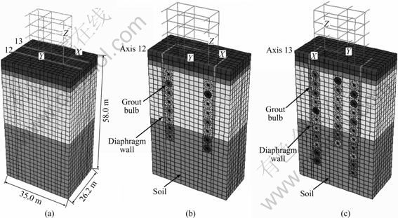
Fig. 5 Finite difference mesh and layout of grout bulbs: (a) Finite difference mesh; (b) Profile along Axis 12; (c) Profile along Axis 13
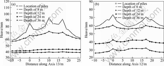
Fig. 6 Surface heave with different depth of grouting: (a) Transverse plot along Axis 13; (b) Transverse plot along Axis 12
With the restriction effect of the grouting-proof curtain, the soil lateral displacements are only two thirds of what observed on the side of Axis 12 under the same depth, as shown in Fig. 7. The maximum value appears at the depth of 8 m where the soil is muddy soil. Due to its low stiffness and high compression, the ground deformation induced by grouting expansion is most concentrated in the soil compression and the surface heave is slight. Pre-grouting is necessary to be conducted to solidify such soft layer for forming a stiffness cushion and playing a jacking effect.
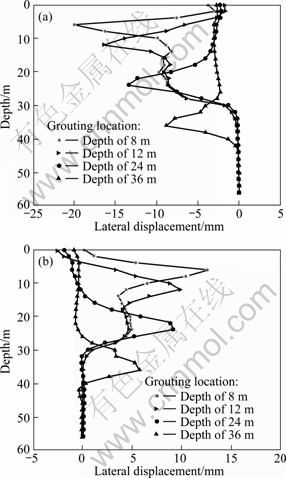
Fig. 7 Lateral displacement with different depth of grouting: (a) 4 m on left of Axis 12 (x=-4 m, y=0); (b) Grouting-proof curtain (x=19.2 m, y=0)
Figure 8 shows the heave calculated by FLAC3D along Axis 13 in comparison with the measured results at the end of grouting. Excepting the discrepancy of about 12 mm for point B9, the computed displacements of other points exist a basically reasonable agreement with the measurements. The possible reason of these differences seems that the chosen grouting efficiency �� does not totally accord to the actual value, and it is necessary to be evaluated through the back-analysis of the recorded surface heaves to minimize the discrepancy between the observed and the corresponding numerical results. Furthermore, with the neglection of the stiffening effect of the wall in the upper building on which point B9 is located, the calculation overestimates the heave of this point and leads to their discrepancies.
Figure 9 shows a comparison of both heaves of observation point A1 at the top of the pile (see Fig. 10) and the soil at the same position during the whole grouting operation. It can be observed that the displacements are almost similar at first, whereas the heave of observation point A1 gradually becomes larger than that of the soil with the raise of grouting depth. A difference of 3.5 cm occurs after finishing heaving under Axis 13 and such inconsistency would produce skin friction along the pile to drag the soil to move upward and form a peak shown in Fig. 6. During the transformation of grouting from Axis 13 to 12, the node velocity of grout bulb at former stage should be free and the model would be re-balanced. Consequently, the subsidence will happen again within the previous lifting region. Such change may explain the phenomenon that after stopping injecting and the grouting pressure is dropped to zero, the heave would gradually decrease within 2-3 h in actual operation.
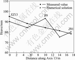
Fig. 8 Calculated and measured heave
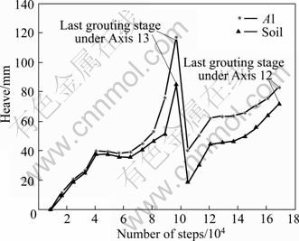
Fig. 9 Comparisons of heave during whole grouting operation

Fig. 10 Observation points on structure
Figure 11 shows the horizontal displacements of the monitoring points S0 and S1 during the whole grouting process under the axes. Both displacements steadily increase after each injection stage under Axis 13. With the decrease of grouting depth, the effect of grouting on structure becomes apparent and hence considerable movement occurs for shallow grouting. As the rising of the second frame could reduce the westward inclining of structure, the lateral displacement transits from the west of 0.25 mm to the east of 0.1 mm at observation point S0 during the injection stages under Axis 12. Due to the adopted beam elements to simulate the restraint of the rest structures on the lateral displacement in this model, this simplification would strengthen such effect compared to the actual situation and make the numerical solutions smaller than the actual deformation.
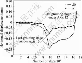
Fig. 11 Horizontal displacement of S0 and S1 during whole grouting operation
5.2 Additional internal forces analysis
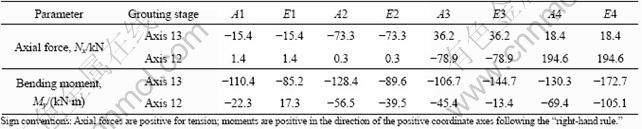
Table 2 lists the additional internal forces induced by grouting in the structural members of the frame. It is shown that an axial compressive force occurs in the columns above the raising area, and a tensile force occurs in the columns above the area where the ground has not yet been heaved. This observation indicates a transfer of axial loading with the process of grouting from Axis 13 to 12 and a reduction in previous grouting region. It is worthy noticing that a maximum tension of 194.6 kN appears in the centre column of Axis 12 due to the uneven heave along this axis (see Fig. 6(b)). Concerning the bending moment values, it can be observed that the bending moment decreases from Axis 13 to 12. The maximum value of about 144.7 kN��m occurring at the observation point E3 is about 27% larger than that at observation point E4 during the last injection stage under Axis 12.
Table 2 Additional internal force and bending moment of structure induced by grouting
5.3 Impact of grout wall stiffness on lateral displacement
Normally, pre-grouting around the lifting region is performed beforehand to form grout wall, which is helpful to preventing the leakage of slurry and limiting the soil lateral expansion. Figure 12 shows the distributions of lateral displacement along depth under different deformation moduli of 20 MPa, 40 MPa, 80 MPa, 120 MPa, besides the condition without grout wall. The lateral displacements decrease with the increasing stiffness of grout wall, whereas the reduction and the increment do not exhibit relationship of direct proportion. That is to say, the resistance to the development of lateral deformation is weakened with the further improvement of stiffness and becomes limited. It is advisable to choose a reasonable deformation modulus of grout wall from in-situ test ahead of heaving to achieve economical and practical purpose.
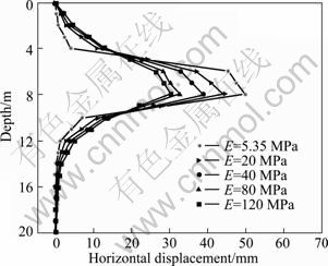
Fig. 12 Influence of grout wall stiffness on lateral displacement (x=19.2 m, y=0)
5.4 Impact of bearing capacity of pile tip on heave
It can be concluded from Fig. 13 that the force required to heave the upper structure is mainly provided from the resistance of pile tip, and the contribution of skin friction along the shaft is very slight and can be ignored. However, with further increase of bearing capacity ��h of pile tip, the increment of heave gradually becomes smaller. When the load distributed in the pile tip reaches the maximum value which certainly exists with an assigned expansion deformation of grout bulbs, the further improvement of the bearing capacity of pile tip is not beneficial to the lifting and the heave will remain almost constant. The results indicate that sufficient bearing capacity of bearing stratum at pile tip is the prerequisite of successful lifting. Since the subsided soil mass or the foundation of inclined building is generally weak and has insufficient bearing capacity for heave, it is necessary to conduct preliminary reinforcement and dense for the bearing stratum, forming a hard layer of a certain thickness to meet the requirements of post-grouting heaving.

Fig. 13 Influence of bearing capacity of pile tip on heave
5.5 Simplified approach
A comparison is presented between the full coupled FDM approach and the simplified approach that neglects the presence of the structure in the determination of the grouting-induced surface heave. It can be observed from Fig. 14 that the presence of the structure affects the surface heave profile. Globally, the structure stiffness causes an increase in the surface heave profile. Due to the consideration of the influence of the structure self-weight and stiffness as well as the neglection of the restraint effect of wall on ground movement, most of the region where the upper structure is located can be still seen as free surface. Consequently, compared to the simplified method, greater expansion force is required in this full coupled FDM approach to cause the same expansion deformation of grout bulb, thus resulting in larger surface heave. It is worthy noticing that the law may turn out contrary for the situation with the same expansion force. Furthermore, it is expected that a mesh refinement may lead to a smoother surface heave profile.

Fig. 14 Surface heave profile along Axis 13
6 Conclusions
1) The approach which imposes radial velocity on outer nodes of grout bulbs to simulate soil expansion is capable of modeling surface heave for the case where a surface building is taken into account.
2) The pile-soil deformation is inconsistent during the process of grouting and the heave of the structure gradually becomes larger than that of soil with the raise of grouting depth. Neglecting the upper structure may generally lead to an underestimation of the heave in term of the model.
3) During the transformation of grouting from Axis 13 to 12, the westward lateral displacement of the upper structure decreases and the additional axial stress state in the columns can be transferred from compression to tension, or vice versa. Besides, settlement would happen again in the previous lifting region due to re-balance of the model.
4) Improving the deformation modulus of grout wall could serve a significant restraint to the horizontal movement of soil, whereas the effect is limited and the choice of a reasonable value in situ grouting is advisable to achieve economical and practical purpose.
5) As the force required to build lifting is mainly provided from the resistance of pile tip, it is of major interest to conduct preliminary reinforcement and compaction for the bearing stratum to meet the requirements of post-grouting heaving.
References
[1] HARRIS D I, MAIR R J, LOVE J P, TAYLOR R N, HENDERSON T O. Observations of ground and structure movements for compensation grouting during tunnel construction at Waterloo Station [J]. Geotechnique, 1994, 44(4): 691-713.
[2] CONTINI A, CIVIDINI A, GIODA G. Numerical evaluation of the surface displacements due to soil grouting and to tunnel excavation [J]. Journal of Geotechnical and Geoenvironmental Engineering, 2007, 7(3): 217-226.
[3] SUN Fen, ZHANG Ding, WANG Chen, FANG Qian, WANG Bing. Analysis of raising pipeline by fracture grouting and its application [J]. Rock and Soil Mechanics, 2010, 31(3): 932-938. (in Chinese)
[4] YI Xiao-min, ZHANG Ding, PANG Tie-zhen, LUO Jian-jun. Practice and monitoring analysis of building lifting due to grouting [J]. Rock and Soil Mechanics, 2009, 30(12): 3777-3782. (in Chinese)
[5] JAMES C N, CHENG W C. Grout efficiency of lifting structure in soft clay [C]// Proceedings of Soil and Rock Instrumentation, Behavior and Modeling. Hunan, China: ASCE, 2009: 1-8.
[6] GRAF E D. Compaction grout [C]// Proceedings of the Grouting, Soil Improvement and Geosynthetics. Reston, VA: ASCE, GSP, 1992: 275-287.
[7] ADEL M E, MOSTAFA E M, ISMAIL M B. Model of compaction grouting [J]. Journal of Geotechnical and Geoenvironmental Engineering, 2001, 127(11): 955-964.
[8] PRASENJIT B, MADHAV M R, PREZZI M. Estimation of heave due to inclined compaction grouting [C]// Proceedings of Advances in Ground Improvement Research to Practice in the United States and China. Florida: ASCE, GSP, 2009: 234-241.
[9] YANG X L, ZOU J F. Estimation of compaction grouting pressure in strain softing soil [J]. Journal of central south University of Technology, 2009, 16(4): 653-657.
[10] WISSER C, EAUGARDE C, BURD H J. Numerical modeling of compensation grouting above shallow tunnels [J]. International Journal for Numerical and Analytical Methods in Geomechanics, 2005, 29(5): 443-471.
[11] NICOLINI E. NOVA R. Modeling of a tunnel excavation in a non-cohesive soil improved with cement injections [J]. Computers and Geotechnics, 2000, 27(4): 2149-2172.
[12] HELMUT F, SCHWEIGER, KUMMERER C. Numerical modeling of settlement compensation by means of fracture grouting [J]. Soils and Foundations, 2004, 44(1): 71-86.
[13] GOLEGGET J. Numerical and analytical studies of the effects of compensation grouting [D]. Austria: Graz University of Technology, 2001.
[14] TANG Zhi-wei, ZHAO Cheng-gang, ZHANG Ding-li. Design of displacement grouting and prediction of the effect for construction of underground structures [J]. China Civil Engineering Journal, 2007, 40(8): 79-84. (in Chinese)
[15] ADDENBROOKE T, ONG J, POTTS DM. Finite-element analysis of a compensation grouting field trial in soft clay [J]. Proceedings of the Institution of Civil Engineers, Geotechnical Engineering. 2002, 115(1): 47-58.
[16] CHAMBOSSE G, OTTERBEIN R. State of the art of compensation grouting in Germany [C]// Proceedings of the 15th International Conference on Soil Mechanics and Foundation Engineering. Istanbul: ISSM G E, 2001: 1511-1514.
[17] ITASCA. FLAC3D �C User��s manual [M]. Minneapolis, MN: Itasca Consulting Group Inc, 2005: 19-22.
[18] CIVIDINI A. An experimental and numerical study of low pressure grouting of granular soils by diluted chemical solutions [J]. International Journal of Geomechanics, 2001, 1(4): 415-440.
(Edited HE Yun-bin)
Foundation item: Project(2007AA11Z134) supported by the National High Technology Research and Development Program of China; Project(10JJ4035) supported by the Natural Science Foundation of Hunan Province, China; Project(2010ybfz046) supported by the Fund of Excellent Doctoral Dissertation of Central South University, China
Received date: 2011-01-18; Accepted date: 2011-05-04
Corresponding author: WANG Xing-hua, PhD, Professor; Tel: +86-731-82655489; E-mail: xhwang@csu.edu.cn
Abstract: A stratum grouting-soil-structure interaction model which simplified the grouted zone into a series of spherical grout bulbs was established using FLAC3D program. The hypothetical non-uniform expansion process to reach an assigned volume strain due to soil compression by grouting was achieved by imposing radial velocity on outer mesh nodes of these spheres. This new method avoids the repeated trial calculation needed in the traditional method which applied a fictitious expanding pressure in the grouting element. The deformation and additional internal forces of structure were investigated during each grouting strategy and the influences of various stiffness of grouting proof curtain and bearing capacity of pile tip were discussed simultaneously. The numerical model is proved to be effective to replicate general behavior expected in the field and is capable of modeling the uplifting effect for the surface structure by grouting.
