

Simulation of electromagnetic-flow fields in Mg melt under pulsed magnetic field
WANG Bin(�� ��), YANG Yuan-sheng(��Ժ��), MA Xiao-ping(����ƽ), TONG Wen-hui(ͯ�Ļ�)
Institute of Metal Research, Chinese Academy of Sciences, Shenyang 110016, China
Received 4 November 2008; accepted 10 March 2009
Abstract:
The effects of a pulsed magnetic field on the solidified microstructure of
Key words:
pulsed magnetic field; numerical simulation; pure Mg; microstructure refinement;
1 Introduction
A fine grain size is beneficial to structure uniformity and mechanical properties for as-cast pure Mg and its alloys[1-3]. Applying electromagnetic vibration to the solidification of metals is a new method developed in recent years[4-6]. Pulsed magnetic field (abbreviated to PMF) processing as a new electromagnetic technology has become one of the most promising new techniques to refine the solidified structure. BAN et al[7-9] applied a pulsed magnetic field to solidification of 2124 Al alloy and found a remarkable change occurring in the solidified structures. GAO et al[10] studied the structural transformation in pure Al under external PMF. The experiments showed that totally equiaxed grains were produced for pure Al[10-12]. WANG et al[13-14] investigated the effect of PMF on the solidified microstructure of AZ91D and Mg-Gd-Y-Zr magnesium alloys. The experimental results showed that the remarkable microstructural refinement is achieved. The average grain sizes of the as-cast microstructure of AZ91D and Mg-Gd-Y-Zr alloys are refined to 104 mm and 47 mm, respectively. Based on this background, the PMF has many advantages, such as simple equipment, high efficiency, low cost, as well as its protecting the melt from pollution because of the non-contact with the melt.
However, the effects of PMF parameters on the pulse current wave are rarely reported, particularly on the electromagnetic force and fluid flow, impeding the development of a refining technique by PMF and making it difficult to obtain a useful technology in practice. Therefore, it is fundamentally important to investigate the mechanism of grain refinement by PMF.
2 Experimental
The experiment was carried out by using a pulsed magnetic field solidification setup. A sketch map of the experimental apparatus is shown in Fig.1. In the equivalent circuit diagram, this setup can be represented by RLC circuit in which the apparatus is symbolized by the capacitor C, the inner resistance R, and the inner inductance L. The coil can be regarded as a consumer load. The pulse frequency and the discharge voltage of the capacitor are 5 Hz and 100/200 V, respectively. The sudden discharge of the capacitor causes a damped sinusoidal current I(t) through the coil, establishing an accompanying magnetic field within several microseconds. During this transient time, magnetic field will change the melt flow and cause large vibration in the melt, which will be analyzed by the finite element method.
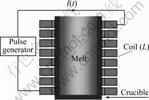
Fig.1 Sketch map of PMF solidification apparatus
Pure Mg was first remelted in an electrical resistance furnace using a mild steel crucible heated to 750 �� for 10 min. Then, the melt was poured into a preheated (to 400 ��) graphite mould with a diameter of 50 mm, height of 100 mm and wall-thickness of 3 mm. The pulsed magnetic field was imposed on the melt until it was completely solidified. Different pulsed magnetic parameters were used in the experiments through changing discharge voltage. The melting, pouring and solidification were conducted under a protective atmosphere of 0.5% SF6 + 99.5% CO2 to prevent oxidation.
The specimens for microstructure observation were made from a transverse section taken at the mid-height of the casting. After grinding and polishing, the specimens were etched with a solution of 95 mL ethanol and 5 mL nitric acid. The microstructures were observed using an optical microscope. The average grain size was measured by the linear intercept method.
3 Finite element analysis
3.1 Numerical procedures
There are three steps in the procedure. The RLC electric circuit is solved first and then it is substituted into the magnetic field model. Finally, the fluid flow model is solved with the acquired electromagnetic force in the magnetic field model. Fig.2 shows a coupled computation chart of the concept��The 2-D transient magnetic analysis is used in the magnetic and flow field model.
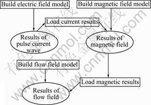
Fig.2 Flow chart of numerical simulation
3.2 Model generation
The RLC circuit analysis determines the current distribution in the electric circuit due to the effect of the applied source voltages on the capacitance. The RLC circuit in this experiment, modeled in ANSYS, is shown in Fig.3. CIRCU124 elements were provided for simulating linear RLC circuit which consists of a resistor, an inductor and a capacitor.
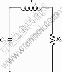
Fig.3 RLC circuit modeled in ANSYS
The magnetic field model is shown in Fig.4(a) and the meshing model is shown in Fig.4(b), which includes the magnesium melt, coil, air and the infinite field. PLANE53 was provided for simulating the magnesium melt, coil and air areas, and INFIN110 for the infinite field. It is easy to control the mesh density and the amount of elements and nodes. The value of the relative permeability of those regions is 1. The electrical resistivities of the magnesium melt and coil are 7.41��10-7 and 1.7��10-8 ��?m, respectively.
The fluid field model is shown in Fig.4(c), and the meshing method of the melt zone is the same as that used for the same zone in the magnetic field model. FLUID141 was used for simulating fluid field. The density and viscosity of the fluid are 1.584 g/cm3 and 7.3 mPa��s, respectively.
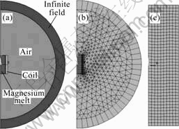
Fig.4 Geometry of model used in ANSYS for magnetic and fluid field: (a) Geometry of magnetic field; (b) Enmeshed model of magnetic field; (c) Enmeshed model of fluid field
4 Analysis and discussion
4.1 Coil current waveform
It is necessary to understand how the current waves run through the coil, for the pulsed magnetic field is induced by the pulsed current. The current waves in the coil as a function of time are shown in Fig.5. Fig.5(a) shows the first pulse current waves as a function of the discharge voltage of the capacitor. As the voltage increases, the amplitude of the current increases, but the damped sinusoidal current wave periods remain unchanged. The time for the current to reach the maximum is 0.001 s, and the maximum value of the current for the 200 V discharge voltage is about 330 A, twice the current when 100 V is used. The whole current waves, including the off period, are shown in Fig.5(b), under the conditions of 5 Hz and 200 V. For the periodical variation of the pulsed current shown in Fig.5(b), only the first pulse current wave is considered in the simulation. In contrast to other types of electromagnetic fields, the main advantage of PMF is the strong energy concentration characteristics for acquiring the peak value of the discharge current in a short time.
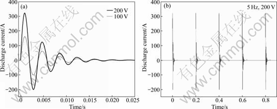
Fig.5 Calculated results for current waves versus time: (a) First pulse current waves influenced by discharge voltage; (b) Current waves with 5 Hz and 200 V PMF treatment
4.2 Magnetic flux density
The calculated results for the magnetic flux density are shown in Fig.6. When the transient magnetic analysis method is used, the magnetic flux density distributions are shown in Fig.6(a). The magnetic flux density decreases with the decrease of distance from the centerline of the billet because of the skin effect of the alternating electromagnetic field. The maximum value of the magnetic flux density emerges at the edge of the melt zone. The direction of the magnetic flux density is approximately parallel to the centerline of the billet. The change of magnetic flux density versus time was also studied, and the magnetic flux density of the node in the radial edge of the billet is shown in Fig.6(b). These magnetic flux densities vary with time. From the comparison of the curves of magnetic flux density with different discharges, it can be observed that the frequencies of both curves are the same. However, the peak value of the magnetic flux density with the 200 V discharge is twice that with the 100 V discharge.
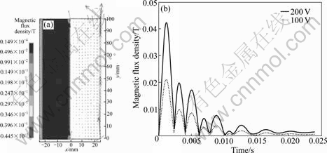
Fig.6 Calculated results for magnetic flux density: (a) Magnetic flux density vectors and contours with discharge voltage of 100 V at time of 0.001 s; (b) Magnetic flux density vs time curves with discharge voltages of 100 V and 200 V
4.3 Magnetic pressure
The calculated results for the magnetic pressure are shown in Fig.7. The direction of the magnetic pressure is approximately vertical to the centerline of the billet. The peak value of the magnetic pressure also emerges at the radial edge of the melt zone and the pressure decreases from the edge to the center. The curves of magnetic pressure of the node (the coordinate position is x=25 mm, y=50 mm) are also plotted as a function of time as shown in Fig.7(b), and the peak value of the magnetic pressure with a discharge of 200 V is four times that with the 100 V discharge.
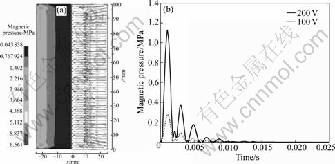
Fig.7 Calculated results for magnetic pressure: (a) Magnetic pressure vectors and contours with discharge voltage of 100 V at time of 0.001 s; (b) Magnetic pressure vs time curves with discharge voltages of 100 V and 200 V
4.4 Velocity of melt
The local velocity differences of the melt are caused by the magnetic pressure. The calculated contours and velocity vectors of the flow field with different discharge voltages at time of 0.001 s are shown in Fig.8. It is found that pattern of the melt flow with the 100 V discharge is the same as that with the 200 V discharge. There are three large circulations in the bulk liquid. The maximum velocity in the melt increases with the increase of the pulse discharge voltage, and emerges in the center of the melt at time of 0.001 s.
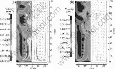
Fig.8 Calculated contours and velocity vectors for flow field with different discharge voltages at time of 0.001 s: (a) 100 V; (b) 200 V
4.5 Microstructural refinement of pure Mg
The morphologies of pure Mg solidified without or with 100 and 200 V PMF treatment for the whole stage of solidification are shown in Fig.9. Without the PMF treatment, the structure of the specimen in Fig.9(a) consists of nearly wholly columnar grains, while with the 100 V PMF treatment, there is a transition from columnar-to-equiaxed growth, and the constitutions of the morphology are equiaxed grains in the center and thin columnar grains in the edge in Fig.9(b). The average equiaxed grain size and columnar grain length are 680 mm and 6.4 mm, respectively. With 200 V PMF treatment, totally refined equiaxed grains are achieved and the average grain size is refined to 260 mm, as shown in Fig.9(c). Therefore, the solidification structure of pure Mg can evidently be refined under the effect of a pulsed magnetic field, and increasing the discharge voltage significantly strengthens the grain refinement effect.
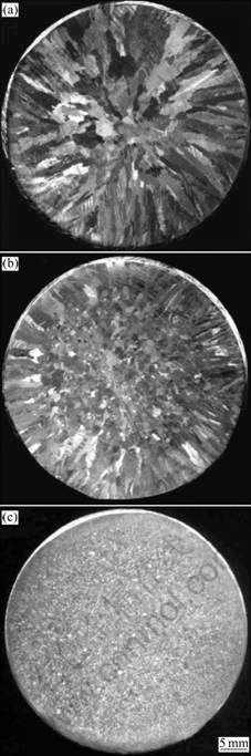
Fig.9 Macrostructures of pure Mg with different discharge voltages for whole stage of solidification: (a) Columnar grains without PMF treatment; (b) Columnar/equiaxed grains with 100 V PMF treatment; (c) Equiaxed grains with 200 V PMF treatment
When PMF is applied to the melt, an electromagnetic force is generated by the coupling of the induction current and the magnetic field in the melt, i.e., f=j��B. As a result, the energy density of the magnetic field represents a pressure acting orthogonal to the magnetic field and towards the center of the melt[15-18]. So, the resulting pressure difference imposed on the melt causes vigorous agitation as soon as the action of the electromagnetic force is exerted.
During the solidification, primary dendrites grow forwards the center and the secondary dendritic arms develop. However, without the deliberate stirring by PMF, the fractured tip of the columnar dendrites or the broken-off dendrite branches promote the formation of an equiaxed structure and prevent further columnar grain formation, and the broken pieces are transported into the bulk liquid and act as nuclei. If the intensity of magnetic field is strong enough by increasing the discharge voltage from 100 V to 200 V, the increase of bulk liquid velocity and the grain refinement effect are strengthened. In addition, the uniform temperature field resulting from the stirring increases the likelihood of nuclei survival, which also contributes to the grain refinement.
5 Conclusions
1) A link between the ANSYS/Emag code and the ANSYS/Flortran code is developed��and a numerical coupled modeling of the electric circuit, magnetic field and the flow field is performed by means of them.
2) The pulse current, magnetic flux density, magnetic pressure and velocity of the melt are functions of time, and the peak values increases with the increase in the discharge voltage.
3) A remarkable structure refinement is achieved when the pulsed magnetic field is applied. The morphology is characterized as wholly equiaxed grains with a 200 V PMF treatment. Melt convection during solidification is the main reason for this grain refinement.
References
[1] KUROTA K, MABUCHI M, HIGASHI K. Review processing and mechanical properties of fine-grained magnesium alloys [J]. J Mater Sci, 1999, 34: 2255-2262.
[2] EMLEY E F. Principles of magnesium technology [M]. Oxford: Pergamon Press, 1966: 200-210.
[3] LEE Y C, DAHLE A K, JOHN D H S. The role of solute in grain refinement of magnesium [J]. Metall Mater Trans A, 2000, 31: 2895- 2906.
[4] VIV?S C. Effect of electromagnetic vibrations on microstructure of continuously cast aluminium alloys [J]. Mater Sci Eng A, 1993, 173: 169-172.
[5] RADJAI A, MIWA K, NISHIO T. An investigation of the effects caused by electromagnetic vibrations in a hypereutectic Al-Si alloy melt [J]. Metall Mater Trans A, 1998, 29: 1477-1484.
[6] YANG Y S, ZHOU Q, HU Z Q. The influence of electric current pulses on the microstructure of magnesium alloy AZ91D [J]. Materials Science Forum, 2005, 488/489: 201-204.
[7] BAN C Y, CUI J Z, BA Q X, LU G M, ZHANG B J. Influence of pulsed magnetic field on microstructures and macro-segregation in 2124 Al-alloy [J]. Acta Metallurgica Sinica, 2002, 15: 380-384.
[8] BAN Chun-yan, CUI Jian-zhong, BA Qi-xian, LU Gui-min, ZI Bing-tao. Solidification structures of LY12 al-alloy under pulsed current and pulsed magnetic field [J]. Chinese Journal of Materials Research, 2002, 16: 322-326.
[9] BAN Chun-yan, BA Qi-xian, CUI Jian-zhong, LU Gui-ming, ZI Bing-tao. Microstructures and distribution of LY12 Al-alloy [J]. Acta Physica Sinica, 2001, 50: 2028-2030.
[10] GAO Y L, LI Q S, GONG Y Y, ZHAI Q J. Comparative study on structural transformation of low-melting pure Al and high-melting stainless steel under external pulsed magnetic field [J]. Mater Lett, 2007, 61: 4011-4015.
[11] GONG Y Y, LUO J, JING J X, XIA Z Q, ZHAI Q J. Structure refinement of pure aluminum by pulse magneto-oscillation [J]. Mater Sci Eng A, 2008, 497: 147-152.
[12] LI J, MA J H, GAO Y L, ZHAI Q J. Research on solidification structure refinement of pure aluminum by electric current pulse with parallel electrodes [J]. Mater Sci Eng A, 2008, 490: 452-456.
[13] WANG Bin, YANG Yuan-sheng, ZHOU Ji-xue, TONG Wen-hui. Microstructure refinement of an AZ91D alloy solidified with pulsed magnetic field [J]. Transaction of Nonferrous Metals Society of China, 2008, 18(3): 536-540.
[14] WANG B, YANG Y S, ZHOU J X, TONG W H. Effect of the pulsed magnetic field on the solidification of Mg-Gd-Y-Zr alloy [J]. Rare Metal Materials and Engineering, 2009, 38: 519-522.
[15] NAKADA M, SHIOHARA Y, FLEMINGS M C. Modification of solidification structures by pulse electric discharging [J]. ISIJ International, 1990, 30: 27-33.
Foundation item: Project(50774075) supported by the National Natural Science Foundation of China; Project(2006BAE04B01-4) supported by Key Technologies R&D Program, China
Corresponding author: YANG Yuan-sheng; Tel: +86-24-23971728; E-mail: ysyang@imr.ac.cn
DOI: 10.1016/S1003-6326(09)60135-7
(Edited by YANG Hua)
