

![]()

Trans. Nonferrous Met. Soc. China 22(2012) 299-304
Interface characteristic of friction stir welding lap joints of Ti/Al dissimilar alloys
CHEN Yu-hua, NI Quan, KE Li-ming
National Defense Key Disciplines Laboratory of Light Alloy Processing Science and Technology,Nanchang Hangkong University, Nanchang 330063, China
Received 11 February 2011; accepted 14 June 2011
Abstract:
Lap joints of TC1 Ti alloy and LF6 Al alloy dissimilar materials were fabricated by friction stir welding and corresponding interface characteristics were investigated. Using the selected welding parameters, excellent surface appearance forms, but the interface macrograph for each lap joint cross-section is different. With the increase of welding speed or the decrease of tool rotation rate, the amount of Ti alloy particles stirred into the stir zone by the force of tool pin decreases continuously. Moreover, the failure loads of the lap joints also decrease with increasing welding speed and the largest value is achieved at welding speed of 60 mm/min and tool rotation rate of 1500 r/min, where the interfacial zone can be divided into 3 kinds of layers. The microhardness of the lap joint shows an uneven distribution and the maximum hardness of HV 502 is found in the middle of the stir zone.
Key words:
interface characteristic; Ti/Al dissimilar alloys; friction stir welding; lap joint;
1 Introduction
Al alloys are widely used in automotive, aerospace and ship industries as high specific strength materials. Ti alloys are also attractive in these fields due to their low density, high specific strength and excellent corrosion- resistance. With the increasing demand for lightweight components, their application is becoming more extensive [1-3]. In some special locations, the complementary characteristics of Ti and Al are required, such as increased strength, lowered mass and cost. Therefore, the joining of Al alloys and Ti alloys is an emergent problem to be solved in industrial application. However, it is difficult to obtain sound dissimilar welds of these two kinds of alloys because of the great differences in their performance, including crystal microstructure, melting point, heat conductivity and coefficient of linear expansion, etc [4, 5]. Using traditional fusion welding method, Al element is severely lost at temperature below the melting point of Ti. The composition of the weld metal is asymmetric and the laminated Ti/Al intermetallics such as Ti3Al, TiAl and TiAl3 can be easily formed, so it is difficult to weld the Ti/Al compound structure by means of fusion welding [6].
To solve this problem, special welding methods have been reported to join these two materials such as pressure welding [7], diffusion bonding [8], vacuum brazing [9], laser welding-brazing [10, 11], liquid phase diffusion welding [12] and friction welding [13]. These studies show that the key issue encountered in welding Al alloy to Ti alloys is the formation of interfacial intermetallic phases [14], which depends on the process related temperature-time cycles. Friction stir welding (FSW) which is a solid-state welding process patented by the Welding Institute (TWI) in 1991 is a potential candidate for the joining of dissimilar materials due to its advantageous lower processing temperature over conventional fusion welding [15]. There are several studies on the FSW of Ti/Al dissimilar alloys at present in the world. DRESSLER [16] joined titanium alloy TiAl6V4 and aluminium alloy 2024-T3 successfully and investigated the microstructure, hardness and tensile strength of the butt joint. It was found that the ultimate tensile strength of the joint can reach 73% that of the 2024-T3 base material. CHEN and NAKATA [17] studied the lap joining of Al-Si alloy and pure titanium by FSW. The maximum failure load of joints reached 62% that of Al-Si alloy base metal with the joints fractured at the interface.
In this work, dissimilar Ti alloy TC1 and Al alloy LF6 were lap jointed by FSW and the interface characteristic of the lap joint was studied in order to provide theoretical guidance to obtain optimal process parameters and improved mechanical properties of the welded joint.
2 Experimental
TC1 Ti alloy and LF6 Al alloy plates with thickness of 2 mm were used in the present study. The chemical compositions and mechanical properties are listed in Tables 1, 2 and 3, respectively.
Table 1 Chemical composition of LF6 (mass fraction, %)
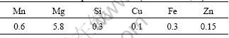
Table 2 Chemical composition of TC1 (mass fraction, %)
![]()
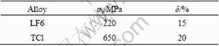
Table 3 Mechanical properties of LF6 and TCl alloys
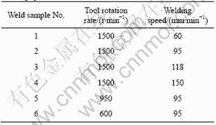
The plates were cut and machined into rectangular welding samples with size of 250 mm��100 mm. The samples were longitudinally lap-welded using an FSW machine. The surfaces of the welding samples were ground with grit paper to remove the oxide film and then cleaned by ethanol before welding. During FSW process, LF6 aluminium alloy was placed over TC1 titanium alloy and they were settled at the advancing side (AS) and the retreating side (RS) of the tool pin, separately (see Fig. 1). A tool with a concaved shoulder of 15 mm in diameter and a cone-threaded pin of 4 mm in diameter and 2.1 mm in length was used. The tilt angle was 2�� from the normal surface of plates. The tool rotation rate (n) and welding speed (v) used in dissimilar FSW process are given in Table 4.
The microstructure and interface characteristic analysis was performed on the cross section perpendicular to the welding direction. A solution of 2 mL HF, 4 mL HNO3 and 94 mL distilled water was chosen as the etchant. Microstructure and element distribution of the weld were observed by optical microscope (OM, 4XB-TV) and scanning electron microscope (SEM, Quata200) equipped with an energy dispersive X-ray spectroscopy (EDS) system. The mechanical properties of the joint were measured by tensile-shear tests which were carried out at room temperature at a crosshead speed of 3 mm/min using a tensile testing machine. The failure loads of the joints were evaluated using 3 tensile specimens cut from the same joint on electronic almighty testing machine (WDW-50) controlled by computer. The shape of the test specimen was rectangular and the width of each specimen was 12.5 mm.
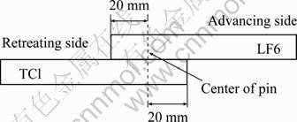
Fig. 1 Schematic diagram of relative position between Ti alloy and Al alloy
Table 4 Experiment parameters of tool rotation rate and welding speed
3 Results and discussion
3.1 Interface macrograph of lap joints with different parameters
The typical surface appearance of friction stir welded Ti/Al joints with the above-mentioned parameters is shown in Fig. 2. As can be seen clearly, the surface is smooth without any defects, indicating an excellent surface appearance in all samples.
It should be noted that the interface macrographs for each lap joint cross-section are very different. It can be seen from Fig. 3 that, at welding speed of 60 mm/min and tool rotation rate of 1500 r/min, the stir zone (SZ) of the weld contains a large amount of Ti alloy particles and the cross-section morphology of the lap joint is excellent (see Fig. 3(a)). The SZ reveals a mixture of Al alloy and titanium pushed away from the titanium surface by the stirring action of the tool pin. When the welding speed increases to 95 and 118 mm/min, the cross-section morphology is also good but the amount of Ti alloy particles in the stir zone of weld decreases (see Fig. 3(b)). This may be ascribed to the reduction of welding heat input and the decrease of plastic flow ability of Ti alloy. Accompanying further increase of welding speed to 150 mm/min, crack occurs on the interface between Ti alloy and Al alloy (see Fig. 3(c)). At welding speed of 95 mm/min and tool rotation rate of 950 and 600 r/min, the tip of tool pin nearly does not touch the surface of lower Ti alloy plate due to the absence of serious softening of Al at lower tool rotation rate. From Figs. 3(d) and 3(e), it can be seen that Al alloy and Ti alloy are joined tightly with little Ti in the SZ.

Fig. 2 Surface appearance of Ti/Al dissimilar alloys lap joint prepared by FSW

Fig. 3 Interface macrographs of lap joint of Ti/Al dissimilar alloys: (a) n��1500 r/min, v��60 mm/min; (b) n��1500 r/min, v��118 mm/min; (c) n��1500 r/min, v��150 mm/min; (d) n��950 r/min, v��95 mm/min; (e) n��600 r/min; v��95 mm/min
3.2 Failure loads of lap joints
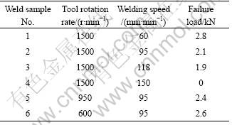
Table 5 lists the corresponding failure loads of the 6 samples above. It can be seen from Table 5 that the failure load decreases with the increase of welding speed when the tool rotation rate is fixed at 1500 r/min. The failure load of the joint is 0 at the tool rotation rate of 1500 r/min and welding speed of 150 mm/min due to the existence of crack on the interface. When the welding speed is 95 mm/min and the tool rotation rates are 950 and 600 r/min, the failure loads of the welded joints are relatively larger than that at the tool rotation rate of 1500 r/min and welding speed of 95mm/min. This may be ascribed to the less amount of intermetallic compound on the interface between Al alloy and Ti alloy since there is little Ti in the SZ (see Figs. 3(d) and 3(e)).
Table 5 Failure loads of lap joints
3.3 Microstructure and element distribution on interface
Figure 4 presents the SEM morphology of M zone as shown in Fig. 3(a). As can be seen clearly, the interfacial zone of TC1/LF6 FSW lap joint exhibits lamellar structure which can be divided into 3 kinds of layers, as indicated by 1, 2 and 3 in Fig. 4. It should be noted that layer 3 (at the bottom of Fig. 4) is white and black stripped structure, which is close to Ti alloy base metal or close to the nugget zone (at the top of Fig. 4). The morphology of layer 2, which is near layer 3 close to Ti alloy base metal, is stripped structure with black particles distributing in the gray matrix. The morphology of layer 1 located between layers 2 and 3 close to the nugget zone is black lamellar structure.
The EDS analysis results of the above three layers are shown in Fig. 5 and Table 6. Obviously, the types and content of elements in layer 1 are almost the same as TC1 base metal, so layer 1 can be inferred as the stripped TC1 base metal which is stirred into the interfacial zone by the force of tool pin. The main element in layer 2 is Al element and there is also a certain amount of Ti and Mg elements. This suggests that layer 2 is the mechanical mixture of TC1 base metal and LF6 base metal. There are only Ti and Al elements in layer 3 and the atomic ratio of Ti and Al is close to 1:1, which indicates the produced Ti-Al intermetallic compounds in this zone.

Fig. 4 SEM image of interfacial zone on welded joint under largest failure load

Fig. 5 EDS analysis of interfacial zone: (a) Layer 1 in Fig. 4; (b) Layer 2 in Fig. 4; (c) Layer 3 in Fig. 4
Table 6 Composition of interfacial zone in Fig. 4 (molar fraction, %)
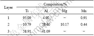
Figure 6 shows the SEM morphology of N zone shown in Fig. 3(c). It can be seen that there is an obvious groove in the interfacial zone (see Fig. 6(a)). Under high power field shown in Fig. 6(b), there are some black blocky-shaped particles (zone 5 in Fig. 6(b)) and bright irregular shape particles (zone 4 in Fig. 6(b)) in the groove.

Fig. 6 SEM morphology of interfacial zone on welded joint under smallest failure load: (a) Groove morphology in interfacial zone; (b) Particles in groove
EDS analysis results of the particles in the groove are shown in Fig. 7. The main elements in the bright irregular shape particle are Al, Ti and Mg, and the molar fractions of the elements are 60.13%, 37.47% and 1.67%, respectively. This suggests that the bright irregular shape particles may be the mixture of Ti-Al intermetallic compounds and LF6 base metal. The main element in the black blocky-shaped particle is 98.67% Si, and the remanent element is 1.33% Ti. These results suggest that the black blocky-shaped particles are Si particles separated from TC1 base metal during the FSW process.
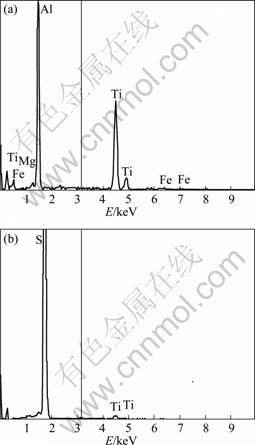
Fig. 7 EDS analysis results of interfacial zone in Fig. 6(b): (a) Zone 4 (b); (b) Zone 5
3.4 Microhardness distribution
The Vickers microhardness values of the TC1/LF6 dissimilar welded joint were measured along the dashed line marked in Fig. 3(a), which was the center axis of the SZ, and the result is shown in Fig. 8.
The microhardness presents an uneven distribution, and the hardness of the stir zone is much higher than that of the base material. The maximum value of the hardness reaches HV 502 in the middle of the stir zone, which is twice that of TC1 base material and 4 times higher than that of LF6 base material. The formation of Ti-Al intermetallic compounds in the SZ is the main reason for the high hardness.
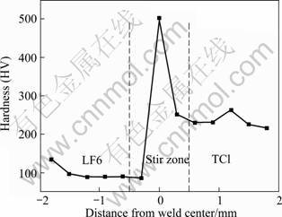
Fig. 8 Microhardness distribution of Ti/Al lap joint made by FSW
4 Conclusions
1) Friction stir welding is suitable for lap jointing of TC1 Ti alloy and LF6 Al alloy dissimilar materials. An excellent surface appearance can be obtained easily.
2) The interface macrograph of the lap joint cross- section at different parameters significantly changes. Accompanying with the increase of welding speed or the decrease of tool rotation rate, the amount of Ti alloy particles stirred into the stir zone by the force of tool pin decreases. At the welding speed of 60 mm/min and the tool rotation rate of 1500 r/min, the interfacial zone of lap joint can be divided into three kinds of layers. When the welding speed increases to 150 mm/min, groove-like crack occurs on the interface.
3) The failure loads of the lap joints decrease with the increase of welding speed. The largest failure load of the joint welded occurs at the tool rotation rate of 1500 r/min and welding speed of 60mm/min, in contrast to that of 0 at tool rotation rate of 1500 r/min and welding speed of 150mm/min.
4) The microhardness of the lap joint presents an uneven distribution, the maximum value of hardness reaches HV 502 in the middle of the stir zone.
References
[1] EYLON D, SEAGLE S R. Titanium technology in the USA��An overview [J]. Journal of Material Science and Technology, 2001, 17(4): 439-443.
[2] YAN Ming-gao, WU Xue-ren, ZHU Zhi-shou. The development status and prospects of aeronautical materials technology [J]. Aeronautical Manufacturing Technology, 2003(12): 19-25. (in Chinese)
[3] CABIBBO M, MARRONE S, QUADRINI E. Mechanical and microstructural characteristics of laser welded titanium-aluminium joints [J]. Welding International, 2005, 19(2): 125-129.
[4] WILDN J, BERGMANN J P. Manufacturing of titanium/aluminum and titanium/steel joints by means of diffusion welding [J]. Welding and Cutting, 2004, 3(5): 285-290.
[5] REN Jiang-wei, LI Ya-jiang, FENG Tao. Microstructure characteristics in the interface zone of Ti/Al diffusion bonding [J]. Materials Letters, 2002, 56(5): 647-652. (in Chinese)
[6] KORENYUK Y M. Interaction of liquid aluminium and solid titanium in fusion welding [J]. Welding Production, 1975, 22(6): 3-5.
[7] SAPRYGIN V D. Pressure welding of aluminium�Csteel and titanium�Caluminium transition pieces for low-temperature service [J]. Welding Production, 1975, 22(6): 29-31.
[8] YAO Wei, WU Ai-ping, ZOU Gui-sheng. Structure and forming process of the Ti/Al diffusion bonding joints [J]. Rare Metal Materials and Engineering, 2007, 36(4): 700-704. (in Chinese)
[9] ZHAO Peng-fei, KANG Hui. Study on vacuum brazing of dissimilar alloys of Al/Ti [J]. Journal of Materials Engineering, 2001, (4): 25-28. (in Chinese)
[10] CHEN Shu-hai, LI Li-qun, CHEN Yan-bin. Formation mechanism of porosity in laser welding-brazing of Ti/Al dissimilar alloys [J]. Rare Metal Materials and Engineering, 2010, 39(1): 32-36. (in Chinese)
[11] NI Jia-ming, LI Li-qun, CHEN Yan-bin, FENG Xiao-song. The characteristic of laser brazing joints of Al/Ti dissimilar alloy [J]. The Chinese Journal of Nonferrous Metals, 2007, 17(4): 617-622. (in Chinese)
[12] SOHN W H, BONG H H, HONG S H. Microstructure and bonding mechanism of Al/Ti bonded joint using Al10Si1Mg filler metal [J]. Materials Science and Engineering A, 2003, 355(1-2): 231-240.
[13] FUJI A, IKEUCHI K, SATO Y S, KOKAWA H. Interlayer growth at interfaces of Ti/Al-1%Mn, Ti/Al-46%Mg and Ti/pure Al friction weld joints by post-weld heat treatment [J]. Science and Technology of Welding and Joining, 2004, 9: 507-512.
[14] FUJI A. In situ observation of interlayer growth during heat treatment of friction weld joint between pure titanium and pure aluminium [J]. Science and Technology of Welding and Joining, 2002, 7: 413-416.
[15] MISHRA R S, MA Z Y. Friction stir welding and processing [J]. Materials Science and Engineering R, 2005, 50: 1-78.
[16] DRESSLER U, BIALLAS G, MERCADO U A. Friction stir welding of titanium alloy TiAl6V4 to aluminium alloy AA2024-T3 [J]. Materials Science and Engineering A, 2009, 526(1-2): 113-117.
[17] CHEN Y C, NAKATA K. Microstructural characterization and mechanical properties in friction stir welding of aluminum and titanium dissimilar alloys [J]. Materials and Design, 2009, 30: 469-474.
Ti/Al���ֺϽ����Ħ������ӽ�ͷ�Ľ�������
����, �� Ȫ, ������
�ϲ����մ�ѧ ��Ͻ�ӹ���ѧ�뼼�������ص�ѧ��ʵ���ң��ϲ� 330063
ժ Ҫ�����ý���Ħ����ʵ��TC1�ѺϽ��LF6���Ͻ����ֲ��ϵĴ�����ӣ����Խ������Խ����о���������ѡȡ�Ĺ��ղ������ܻ�����õı�����Σ���ÿһ�ֹ��ղ����µĽ�����ò��ͬ�����ź����ٶȵ����ӻ����ͷת�ٵĽ��ͣ�����������뺸�������ѺϽ����ӵ��������٣����Ҵ�ӽ�ͷ�Ŀ����غ�Ҳ���ź����ٶȵ���߶����͡��������ٶ�Ϊ60 mm/min������ͷ��ת�ٶ�Ϊ1500 r/minʱ����ͷ�Ŀ����غɴﵽ���ֵ����ʱ�Ľ��������Էֳ����㡣��ӽ�ͷ����Ӳ�ȷֲ������ȣ���������������Ӳ��ֵ��ߴ�HV502��
�ؼ��ʣ�����������Ti/Al���ֺϽ𣻽���Ħ��������ӽ�ͷ
(Edited by FANG Jing-hua)
Foundation item: Project (2011BAB206006) supported by the Natural Science Foundation of Jiangxi Province, China; Project (2009ZE56011) supported by the Aviation Science Funds of China; Project (GJJ12411) supported by the Education Department of Jiangxi Province, China
Corresponding author: CHEN Yu-hua; Tel: +86-79-13863023; E-mail: ch.yu.hu@163.com
DOI: 10.1016/S1003-6326(11)61174-6
Abstract: Lap joints of TC1 Ti alloy and LF6 Al alloy dissimilar materials were fabricated by friction stir welding and corresponding interface characteristics were investigated. Using the selected welding parameters, excellent surface appearance forms, but the interface macrograph for each lap joint cross-section is different. With the increase of welding speed or the decrease of tool rotation rate, the amount of Ti alloy particles stirred into the stir zone by the force of tool pin decreases continuously. Moreover, the failure loads of the lap joints also decrease with increasing welding speed and the largest value is achieved at welding speed of 60 mm/min and tool rotation rate of 1500 r/min, where the interfacial zone can be divided into 3 kinds of layers. The microhardness of the lap joint shows an uneven distribution and the maximum hardness of HV 502 is found in the middle of the stir zone.
