
Article ID: 1003-6326(2005)05-0965-06
Hydrogen generation via hydrolysis of nanocrystalline MgH2 and MgH2-based composites
HU Lian-xi(����ϲ), WANG Er-de(������)
(School of Materials Science and Engineering, Harbin Institute of Technology, Harbin 150001, China)
Abstract:
Nanocrystalline MgH2 and MgH2-based composites with 25%(mass fraction) of Al, Ca, or CaH2 as an individual additive respectively were prepared by ball milling. The crystallite size and morphology of the as-milled powders were characterized and their hydrolysis behaviours were investigated in comparison with commercial polycrystalline MgH2. The results show that the crystallite size of both MgH2 and MgH2-based composites is reduced to less than 13nm after milling for 15h. Due to its enhanced specific surface area and unique nanocrystalline structure, the as-milled MgH2 shows much better hydrolysis kinetics than the commercial polycrystalline MgH2, with the hydrolysed fraction upon hydrolysing for 70min enhances from 7.5% to about 25%. As compared with the as-milled MgH2, the MgH2-based composites with either CaH2 or Ca as an additive present further greatly improved hydrolysis kinetics, with the hydrolysed fraction for 80min achieving about 76% and 62% respectively. However, the addition of Al doesn��t show any positive effect on the improvement of the hydrolysis kinetics of MgH2.
Key words:
ball milling; nanostructured material; MgH2; chemical hydride; hydrogen generation by hydrolysis CLC number: TK91;
Document code: A
1 INTRODUCTION
Proton exchange membrane(PEM) fuel cells which use hydrogen and air to produce electricity are attractive power sources to replace traditional batteries and generators in providing clean energy for transportation and personal electronics applications where low system mass and portability are important[1-5]. An interesting source of hydrogen for hand-portable PEM fuel cells is the aqueous hydrolysis of chemical hydrides[6-9]. Generally, chemical hydrides which can be used to produce hydrogen by hydrolysis include a variety of alkaline and alkaline earth metal hydrides, and some alkaline metal borohydrides or aluminohydrides. Nevertheless, the hydrolysis reaction kinetics differs remarkably between these chemical hydrides. The reaction is either extremely vigorous or even explosive for some chemical hydrides such as LiH, NaH, and LiAlH4, or it is too slow for practical applications in some other cases. Therefore, the control of the hydrolysis reaction becomes one major problem associated with this method of hydrogen production. For example, NaH is coated with a resin film[10], and LiH is prepared as a slurry with light mineral oil[11, 12] to reduce the hydrolysis reaction rate, while the hydrogen generation by hydrolysis of ligands stabilized aqueous solution of NaBH4 or LiBH4 needs to be catalyzed to achieve a practical reaction rate[13-15]. As a result, material cost increases significantly, which makes such chemical hydrides unfavorable for practical application.
As compared with the chemical hydrides mentioned above, magnesium hydride (MgH2) may be considered a strong candidate for the production of hydrogen via the hydrolysis reaction, because it is available at a relatively low cost. The hydrolysis of MgH2 is described by the following equation:
MgH2+2H2O=Mg(OH)2+2H2(1)
The theoretical hydrogen yield of the reaction above is 6.4%(mass fraction) when the mass of water is taken into account. In fuel cell applications, if the water produced by the fuel cell is conducted to the chemical hydride, then the yield can be enhanced to 15.2%(mass fraction). Unfortunately, the hydrolysis reaction of conventional polycrystalline MgH2 is rather slow and incomplete, because of the formation of the hydrolysis product, Mg(OH)2, as a passivation layer on the non-reacted MgH2.
The objective of this investigation is to improve the kinetics of MgH2 hydrolysis reaction and try to achieve reaction completion by the nanocrystallization of MgH2, and the addition of a small fraction of a second material which is supposed to promote hydrolysis to synthesize nanocrystalline MgH2-based composites, via the ball milling technique.
2 EXPRRIMENTAL
The starting magnesium hydride (95% MgH2, 5% Mg) was purchased from Th. Goldschmidt. The additives chosen to make MgH2-based composites were Al, Ca, and CaH2, respectively. The purity of the additives was higher than 99%. Nanocrystalline MgH2 and MgH2-based composites were prepared by ball milling in argon atmosphere using a Spex8000 shaker mill. Both the raw and the as-milled materials were kept in a glove box filled with pure argon. The milling vial and balls were made of stainless steel. The mass of powders milled for each batch was 3g, and the ball to powder mass ratio was 8��1. The phase structure and morphology of the as-milled powders were examined by X-ray diffraction(XRD) analysis and scanning electron microscopy(SEM), respectively. The crystallite size of the as-milled powders was evaluated by calculation based on the half-width of the most intensive diffraction peaks of the XRD patterns.
The hydrolysis tests were carried out in a special device which was provided with a flask-like reactor. The flask-like reactor had two openings, one for water introduction and the other for hydrogen exhaust. For each run of hydrolysis test, 250mg of MgH2 or MgH2-based composite powders were loaded into the flask reactor and allowed to react with 100mL of deionized water at room temperature. The hydrogen release during hydrolysis was measured by using a ADM2000 gas flow meter, with its inlet connected to the hydrogen exhaust opening of the reactor and the output to a data acquisition and processing computer. For evaluation of the results, the hydrolysed fraction was plotted as a function of time, where the hydrolysed fraction was defined as the ratio of the volume of hydrogen gas actually released to its theoretical yield, assuming that all materials were completely hydrolysed.
3 RESULTS AND DISCUSSION
3.1 Structure and morphology of as-milled powders
Fig.1 shows the XRD patterns of the raw MgH2 and representative as-milled MgH2 and MgH2-based composite powders. It reveals that MgH2 neither decomposes nor reacts with the additives Al, Ca, or CaH2 during milling up to 15h, despite the fact that a small fraction of the raw tetragonal MgH2 was transformed into ��-MgH2 after milling for more than 3h, as reported by Hout et al[16]. This means that no loss of hydrogen included in the raw materials happens during milling, and the MgH2-based composites prepared by ball milling up to 15h remain to be mechanical mixtures of MgH2 and the additives. On the other hand, the crystallite size of the as-milled powders decreases drastically with increasing milling time. Calculations based on the XRD patterns show that 3h milling leads to nanocrystalline as-milled MgH2 powders with average crystallite size of about 58nm, and 15h milling reduces further the crystallite size to less than 13nm for both MgH2 and MgH2-based composite powders, as can be seen from Table 1.
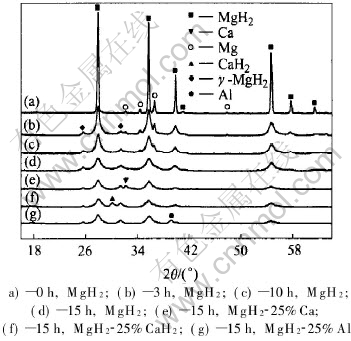
Fig.1 XRD patterns of raw and as-milled powders
Table 1 Average crystallite size of various as-milled powders (nm)
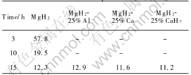
Fig.2 shows the SEM micrographs of both raw MgH2 and representative as-milled powders. It can be seen that ball milling changes the morphology of the powders drastically. The MgH2 powders before milling are flat solid particles with an average size of about 30��m��30��m��10��m(Fig.2(a)), while the as-milled powders by milling for 3h are basically spherical powder agglomerates with an average size of about 6��m. Such are formed by cold welding of much finer sub-particles (Fig.2(b)). When the milling time prolongs to 15h, it doesn��t obviously change the size and morphology of such powder agglomerates but seems to reduce the size of the sub-particles forming the powder agglomerates (Fig.2(c)) seems to be reduced. Further, a comparison between the 15h-milled MgH2 and MgH2-25%CaH2 composite by SEM observation reveals no difference in powder size and morphology, except for that the sub-particles forming the powder agglomerates seem to be smaller in the latter case, as shown in Fig.2(d). On the basis of SEM observation, the average specific surface area of the as-milled powders by milling for more than 3h is estimated to be about 2.0-2.5 times larger than that of the raw MgH2 powders.
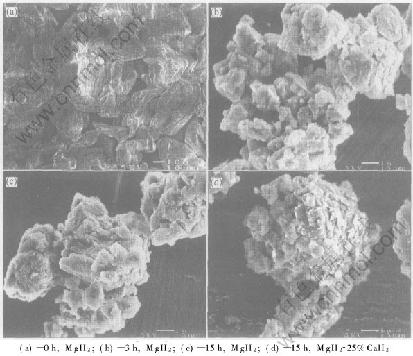
Fig.2 Morphologies of raw and as-milled powders
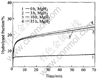
Fig.3 Hydrolysed fraction vs time for MgH2 milled for different time
3.2 Hydrolysis of MgH2/H2O system
Fig.3 shows the variation of hydrolysed fraction with time during hydrolysis of commercial polycrystalline (0h) and mechanically milled (3h, 10h, 15h) nanocrystalline MgH2. For both the polycrystalline and the nanocrystalline MgH2, a fast initial hydrolysing takes place upon the introduction of water. This initial stage of hydrolysis can last only for about 30-40s, achieving 5%-6% of hydrolysed fraction for the polycrystalline MgH2, and 15%-17% of hydrolysed fraction for the nanocrystalline MgH2 respectively. After that, the hydrolysis reaction is either almost stopped as in the case for the polycrystalline MgH2, or slowed down significantly as in the case for the nanocrystalline MgH2, due to the formation of the passivation layer of Mg(OH)2. Indeed, the polycrystalline MgH2 produces very little hydrogen after the initial hydrolysing stage. In comparison, the as-milled nanocrystalline MgH2 can keep on hydrolysing after the initial stage of hydrolysis. However, the reaction kinetics is still insufficient, and the overall hydrogen produced by the 15h-milled nanocrystalline MgH2 achieves only about 27% of its theoretical hydrogen production capacity after hydrolysis for 70min.
Taking it for granted that the hydrolysis of MgH2, like any other solid-liquid reactions, should take place at the MgH2/H2O interface, we believe that the hydrolysed fraction associated with the initial hydrolysing upon the introduction of water should be directly proportional to the specific surface area of the MgH2 powders. Owing to the fact that the mechanically milled nanocrystalline MgH2 powders have a much larger average specific surface area, the hydrolysed fraction due to this initial hydrolysis is consequently much higher for the nanocrystalline MgH2 (15%-17%) than for the polycrystalline MgH2 (5%-6%). In view of the passivation nature of the resultant Mg(OH)2 layer formed by hydrolysing on the MgH2 powder surface, it is expected that the further hydrolysis after the fast initial hydrolysing is very difficult to proceed, as seen for the polycrystalline MgH2. As compared with the polycrystalline MgH2, the hydrolysis of the mechanically milled nanocrystalline MgH2 can keep going after the initial hydrolysis stage, in despite of its insufficient rate. This is possibly attributed to the slow but successive breakdown of some powder agglomerates into individual sub-particles, giving rise to new MgH2/H2O interface for further hydrolysis, and also to the massive crystallite grain boundaries and lattice defects in the mechanically milled nanocrystalline MgH2, which may act as diffusion paths for both anionic and cationic ions and thus make some localized hydrolysis go into the MgH2 particles despite the formation of the passivation layer in the initial hydrolysis stage.
3.3 Hydrolysis of MgH2-based composites/H2O system
Although the hydrolysis reaction kinetics of the mechanically milled nanocrystalline MgH2 is much better than that of the polycrystalline MgH2, it is still insufficient for practical application. To achieve faster reaction kinetics, we prepared mechanically milled nanocrystalline MgH2-based composites by adding some additives into MgH2, which were supposed to leach away and thus help to expose fresh MgH2 surface by their own hydrolysis. Then the hydrolysis of MgH2 can keep going at a relatively higher rate after the initial hydrolysing stage. Of course, such additives should by nature react readily with water and have acceptable theoretical hydrogen yields, so that the MgH2-based composites retain high overall hydrogen production capacities. Therefore, Al, Ca, and CaH2 were chosen for the test. These additives were supposed to react with water as follows, respectively:
Al+3H2O=Al(OH)3+3/2H2(2)
Ca+2H2O=Ca(OH)2+H2(3)
CaH2+2H2O=Ca(OH)2+2H2(4)
It should be mentioned that Al was chosen as one of the additives was mainly due to the consideration that it has a higher theoretical hydrogen yield than Ca when hydrolysed as described above. In addition, the product of hydrolysis, Al(OH)3, is supposed to be acidic in the alkaline Mg(OH)2 solution, and therefore it may possibly help to improve the hydrolysis of MgH2 by suppressing the pH value of the matrix Mg(OH)2 solution.
Fig.4 shows a comparison in the hydrolysis kinetics between the 15h-milled nanocrystalline MgH2 and MgH2-25%Al(mass fraction) composite. Surprisingly, it is found that both the hydrolysed fraction due to the initial hydrolysis stage and the hydrolysis kinetics after that are even worse for the 15h-milled MgH2-25%Al composite than for the 15h-milled MgH2. This is a fact contrary to our early expectation. The reason why the addition of Al has no positive effect on the hydrolysis of MgH2 probably lies in that the product of Al hydrolysis, Al(OH)3, is not soluble even in Mg(OH)2 solution, therefore it is very difficult or impossible for the Al constituent to keep hydrolysing after the formation of the passive Al(OH)3 layer. That is to say, no leaching effect can be achieved by the addition of Al. This suggests that Al can not be used to improve the hydrolysis kinetics of MgH2.
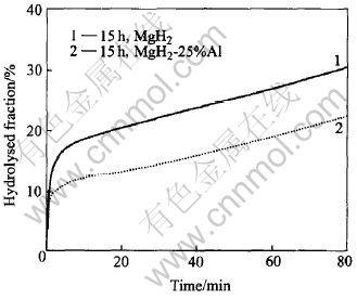
Fig.4 Comparison in hydrolysis kinetics between 15h-milled MgH2 and MgH2-25%Al composite
Fig.5 shows a comparison in hydrolysis kinetics between 15h-milled nanocrystalline MgH2 and MgH2-25%Ca composite. It is noted that, though the hydrolysed fraction due to the initial hydrolysis is nearly the same (about 15%) for both materials, the as-milled MgH2 and MgH2-based composite powder agglomerates have the same feature in size and morphology. The reaction kinetics after the initial stage of hydrolysis is much faster for the MgH2-25%Ca composite, with about 50% of hydrolysed fraction achieved in 30min. This can be attributed to the hydrolysis of the Ca constituent in the MgH2-25%Ca composite, what is more, to its leaching effect which results in exposed fresh MgH2/H2O interface for MgH2 to go on hydrolysing, the product of Ca hydrolysis, Ca(OH)2, is soluble. Due to the progressive consumption of the Ca constituent during hydrolysis, the reaction rate of the MgH2-25%Ca composite decreases with increasing time, as can be seen from the change of the slope of the hydrolysed fraction vs time curves. After hydrolysing for about 45min when an overall hydrolysed fraction of about 57% is reached, a nearly constant reaction rate similar to that of the mechanically milled MgH2 is observed, suggesting that the Ca constituent in the composite is probably completely exhausted and therefore the further hydrolysis process relies on the same mechanism as in the case of the mechanically milled MgH2. Due to the leaching effect of Ca, the hydrolysed fraction of the 15h-milled MgH2-25%Ca composite achieves 62% in 80min, while that of the 15h-milled MgH2 is only about 31%.
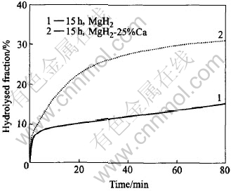
Fig.5 Comparison in hydrolysis kinetics between 15h-milled MgH2 and MgH2-25%Ca composite
Fig.6 shows a comparison in hydrolysis kinetics between 15h-milled nanocrystalline MgH2-25%Ca and MgH2-25%CaH2 composites. It is noted that, despite the same hydrolysis reaction percentage achieved by the initial hydrolysing upon the introduction of water for both materials, the 15h-milled MgH2-25%CaH2 composite has, after this initial stage of hydrolysis, a further faster hydrolysis kinetics than the 15h-milled MgH2-25%Ca composite, with more than 65% of hydrolysed fraction observed in less than 20min. This can be mainly attributed to the fact that CaH2 not only gives rise to soluble hydrolysis product, Ca(OH)2, but also has a faster intrinsic hydrolysis kinetics than Ca, which leads to a faster leaching effect and therefore a better improved overall hydrolysis kinetics for the MgH2-25%CaH2 composite. For the same reason, the CaH2 constituent is supposed to exhaust faster than the Ca constituent during hydrolysis. Therefore, upon hydrolyzing for about only 30min of hydrolysis, when the hydrolysed fraction achieves about 70%, the reaction rate of the 15h-milled MgH2-25%CaH2 composite is also slowed down to almost the same as that observed during hydrolysis of the 15h-milled MgH2, due to the complete exhaustion of the CaH2 constituent in the composite. According to Eqns.(3) and (4), the hydrogen production capacity of CaH2 is almost twice as much as that of Ca, thus the hydrolysed fraction achieved upon the consumption of a certain amount of CaH2 in the case of the MgH2-25%CaH2 composite should be consequently higher than that achieved upon the consumption of the same amount of Ca in the case of the MgH2-25%Ca composite, which also contributes to the faster overall hydrolysis kinetics pertaining to the MgH2-25%CaH2 composite. As a consequence, the hydrolysed fraction of the 15h-milled MgH2-25%CaH2 composite achieves 76% in 80min, which is 14% more than that of the 15h-milled MgH2-25%Ca composite.
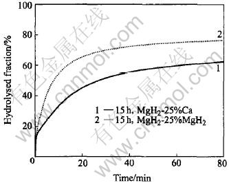
Fig.6 Comparison in hydrolysis kinetics between 15h-milled MgH2-25%Ca and MgH2-25%CaH2 composite
4 CONCLUSIONS
1) The hydrolysis reaction of MgH2 is in nature very fast, as seen in the initial stage of hydrolysis of the commercial polycrystalline MgH2. The main problem with the hydrolysis of the MgH2/H2O system lies in the formation of the passivation layer of Mg(OH)2, which hinders the retained MgH2 from further hydrolysis.
2) As compared with the polycrystalline MgH2, the mechanically milled nanocryatalline MgH2 improves hydrolysis kinetics, attributed to its larger specific surface area and unique structure. However, the hydrolysis rate after the initial stage of hydrolysis is still insufficient for practical application. For example, the hydrolysed fraction of the 15h-milled MgH2 achieved in 80min is only about 31%.
3) Attributed to the fact that Ca and CaH2 react readily with water giving rise to hydrogen and soluble calcium hydroxide, Ca(OH)2, which results in exposed fresh MgH2/H2O interface for MgH2 to keep hydrolysing. The hydrolysis kinetics after the initial stage of hydrolysis for both the 15h-milled nanocrystalline MgH2-25%Ca and the MgH2-25%CaH2 composite is much faster than that of the 15h-milled nanocryatalline MgH2, with the hydrolysed fraction achieving in 80min about 62% for the former and 76% for the latter respectively, suggesting that both CaH2 and Ca are very effective additives to improve the hydrolysis kinetics of MgH2. The reason that CaH2 is more effective than Ca lies in that it has a faster intrinsic hydrolysis kinetics and higher hydrogen production capacity.
4) The hydrolysis kinetics of the 15h-milled nanocrystalline MgH2-25%Al composite is not better but a little worse than that of the 15h-milled nanocrystalline MgH2, attributed possibly to the insolubility of its hydrolysis product, Al(OH)3, in the matrix Mg(OH)2 solution. This suggests that Al can not be used to improve the hydrolysis kinetics of MgH2.
REFERENCES
[1]Lipman T E, Edwards J L, Kammen D M. Fuel cell system economics: comparing the costs of generating power with stationary and motor vehicle PEM fuel cell systems [J]. Energy Policy, 2004, 32: 101-125.
[2]Patil A S, Dubois T G, Sifer N, et al. Portable fuel cell systems for America��s army: technology transition to the field [J]. Journal of Power Sources, 2004, 136: 220-225.
[3]Chu D, Jiang R, Gardner K, et al. PEM fuel cells for communication applications [J]. Journal of Power Sources, 2001, 96: 174-178.
[4]Agbossou K, Chahine R, Hamelin J, et al. Hydrogen energy systems for remote applications [J]. Journal of Power Sources, 2001, 96: 168-173.
[5]Oliver J M, Alan C, Eric C. Low-cost light weight high power density PEM fuel cell stack [J]. Electrochimica Acta, 1998, 43: 3829-3833.
[6]Aiello R, Matthews M A, Reger D L, et al. Production of hydrogen from novel chemical hydrides [J]. International Journal of Hydrogen Energy, 1998, 23: 1103-1108.
[7]Stearns J E, Matthews M A, Reger D L, et al. The thermal characterization of novel complex hydrides [J]. International Journal of Hydrogen Energy, 1998, 23: 469-474.
[8]Aiello R, Sharp J H, Matthews M A. Production of hydrogen from chemical hydrides via hydrolysis with steam [J]. International Journal of Hydrogen Energy, 1999, 24: 1123-1127.
[9]Kong V C Y, Foulkes F R, Kirk D W, et al. Development of hydrogen storage for fuel cell generators (��): hydrogen generation using hydrolysis hydrides [J]. International Journal of Hydrogen Energy, 1999, 24: 665-670.
[10]DiPietro J P, Skolnik E G. Analysis of sodium hydrided-based hydrogen storage system being developed by PowerBall Technologies [EB/OL]. http://www.eere.energy.gov/hydrogenandfuelcells/annual_review2000.html, 2005.
[11]Breault R W, Rolfe J, McClaine A. Hydrogen transmission/storage with a chemical hydride/organic slurry [EB/OL]. http://www.eere.energy.gov/hydrogenandfuelcess/annual_review1999.html, 2005.
[12]McClaine A W, Breault R W, Larsen C, et al. Hydrogen transmission/storage with metallic hydride-organic slurry and advanced chemical hydride/ hydrogen for PEMFC vehicles [EB/OL]. http://www.eere.energy.gov/hydrogenandfuelcess/annual_review2000.html, 2005.
[13]Steven C A, Sharp-Goldman S L, Janjua M S, et al. A safe, portable, hydrogen gas generator using aqueous borohydride solution and Ru catalyst [J]. International Journal of Hydrogen Energy, 2000, 25: 969-975.
[14]Steven C A, Sharp-Goldman S L, Janjua M S, et al. An ultrasafe hydrogen generator: aqueous, alkaline borohydride solutions and Ru catalyst [J]. Journal of Power Source, 2000, 85: 186-191.
[15]Yoshitsugu K, Ken-ichirou S, Kazuhiro F, et al. Hydrogen generation using sodium borohydride solution and metal catalyst coated on metal oxide [J]. International Journal of Hydrogen Energy, 2002, 27: 1029-1035.
[16]Hout J, Liang G, Boily S, et al. Structural study and hydrogen sorption kinetics of ball-milled magnesium hydride [J]. Journal of Alloys and Compounds, 1999, 293-295: 495-460.
Received date: 2005-01-07; Accepted date:2005-05-04
Correspondence: HU Lian-xi, Professor, PhD; Tel: +86-451-86418613; E-mail: hulx@hit.edu.cn
