
J. Cent. South Univ. (2012) 19: 1823-1831
DOI: 10.1007/s11771-012-1215-y![]()
Linear and nonlinear control of a robotic excavator
GU Jun(�˾�)1, MA Xian-dong2, NI Jun-fang(�߿���)1, SUN Li-ning(������)1
1. School of Mechanical and Electric Engineering, Soochow University, Suzhou 215006, China;
2. Engineering Department, Lancaster University, Lancaster, LA1 4YR, UK
? Central South University Press and Springer-Verlag Berlin Heidelberg 2012
Abstract:
Various control systems for a robotic excavator named LUCIE (Lancaster University Computerized and Intelligent Excavator), were investigated. The excavator is being developed to dig trenches autonomously. One stumbling block is the achievement of adequate, accurate, quick and smooth movement under automatic control. Here, both classical and modern approaches are considered, including proportional-integral-derivative (PID) control tuned by conventional Zigler-Nichols rules, linear proportional-integral-plus (PIP) control, and a novel nonlinear PIP controller based on a state-dependent parameter (SDP) model structure, in which the parameters are functionally dependent on other variables in the system. Implementation results for the excavator joint arms control demonstrate that SDP-PIP controller provides the improved performance with fast, smooth and accurate response in comparison with both PID and linearized PIP control.
Key words:
1 Introduction
The civil and construction industries currently deploy a large number of manually controlled plants for a wide variety of tasks within the construction process. The excavation of foundations, general earthworks and earth removal tasks are activities which involve the machine operator in a series of repetitive operations. Automation is likely to provide a number of benefits such as improving efficiency, quality and operator safety.
However, there are still a few real commercially intelligent construction robots that have been applied. In this regard, one persistent stumbling block for system developers is the achievement of adequate accurate, quick and smooth movement under automatic control. Since the behaviour of hydraulically driven manipulators is dominated by the highly nonlinear, lightly damped dynamics of hydraulic actuators [1], the design of a controller for such a system is therefore very much influenced by the behaviour of hydraulic actuators. Together with outside uncertainties such as the soil-tool interaction during digging, varying loads and speeds, the control problem is generally difficult. These difficulties are addressed, and a wide range of classical and modern design methods have been employed [2-8].
In this work, a robotic excavator named the Lancaster University Computerized and Intelligent Excavator (LUCIE) is considered, which is based on a commercial manual hydraulic excavator. LUCIE is developed with the ultimate aim to be able to accept a program of trench locations and dimensions and then traverse a building site and dig a series of trenches meeting these specifications [9]. In moving towards the target of automatic excavation, the most important sub-target is to keep the bucket moving quickly, smoothly and accurately along a specified path. However, the nonlinear joint dynamics can sometimes yield an oscillatory response for bucket position. In order to maintain smooth control, previous control algorithms have typically utilized a relatively slow control action. In Ref. [6], a nonlinear PIP control methodology based on a quasi-linear model structure is utilized for a 1/5th-scale laboratory excavator to improve the control performance of the joint angles. However, as for the full scale system, the nonlinearity of dynamics is much more severe compared with that of the small scale excavator.
In this regard, this work considers both classical and modern approaches, including proportional-integral- derivative (PID) control tuned by conventional Ziegler-Nichols rules, linear proportional-integral-plus (PIP) control, which can be interpreted as one logical extension of the conventional PI approach [10-11], and a novel nonlinear PIP design based on a quasi-linear model structure in which the parameters vary as a function of the state variables [12]. By comparing the approaches, it is anticipated that an improved understanding of the problems associated with this particular plant will emerge. It will benefit the high level controller, which is responsible for planning activities, to couple with appropriate low level control of each joint.
2 LUCIE architecture
A JCB 801 mini excavator is utilized as the platform for the LUCIE project, as illustrated in Fig. 1. The machine has an operating mass of 1.4 t and is less than 1 m wide. It has a bucket capacity of about 9 200 N and a maximum vertical digging depth of about 1.5 m.
It has been refitted with electro-hydraulic servo valves, associated sensors and a computer control system, to allow for the development, experimental evaluation and refinement of the new intelligent control systems. The sensory equipment built into LUCIE mainly includes four potentiometers on the joints for angle measurement, a two-axis tilt sensor, a Leuze RotoScan RS3 optical laser distance sensor for obstacle detection at a range of up to 15 m, a Trimble 7 400 Msi series satellite GPS for location and navigation.
All of the arm movements are hydraulically driven as follows (referring to the numbers in Fig. 1):
1) Movement of the arm in the (x, y) vertical plane uses two hydraulic cylinders that control the boom and dipper, respectively.
2) Rotation of the bucket at the end of the dipper, in the same vertical plane, uses another cylinder.
3) Rotation of the cab at its connection to the undercarriage effectively provides the movement for the arm in a horizontal plane (slew).
4) Movement up and down of a dozer blade at the front of the undercarriage.
5) Independent movement of two parallel caterpillar tracks for skid-steer movement of the whole platform.
As shown in Fig. 2, LUCIE relies on three embedded PC 104 computers. High level controller (HLC) is responsible for the planning of activities and navigation; Low level controller (LLC) is responsible for driving the valves and tracks by commands that are issued either by other processors or the joysticks; Safety manager (SM) is used to ensure that the machine remains in a safe stable condition. The partially observable Markov decision processes (POMDP) technique is utilized for safe and effective navigation of the robotic excavator in hazardous environments [13]. The communication between these computers is provided by CAN-Bus (controller area network).
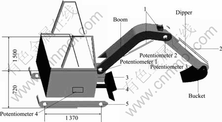
Fig. 1 LUCIE excavator (Unit: mm)
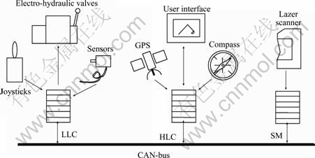
Fig. 2 LUCIE control system architecture
3 Kinematics
The kinematic model is developed to support analysis and planning of motions of the excavator. For automatic digging, it is necessary to be able to place the bucket at a specific location. Bucket placement can be accomplished by adjusting the angles of joint arms. The mathematical expressions that relate the position of the bucket to the axis positions, and then to the angles of joint arms are called the kinematic equations. Figure 3 shows the geometry of the system, where
![]() (1)
(1)
![]() (2)
(2)
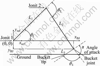
Fig. 3 LUCIE kinematics
The coordinates of the tip of the bucket are then found as follows:
![]() (3)
(3)
![]() (4)
(4)
The inverse kinematic equations for ��1 and ��2 are then
![]() (5)
(5)
![]() (6)
(6)
4 Trajectory planning
During excavation, it is sometimes necessary for the trajectory of the tip of the bucket to be a straight line. For example, when LUCIE is dragging in the ground in order to complete a flat bottomed trench, the trajectory of the bucket is a straight horizontal line. Another example is that once the bucket has been filled, it must then be removed from its position in the trench and moved to the point at which it is to be emptied and then moved back to continue digging. This process should be completed as rapidly as possible and a straight line between the two points is the shortest trajectory.
As for a straight-line trajectory, the simplest way to design the path is to divide the distance from the set start position to the set end position by the operation time in order to create evenly spaced sub-targets. However, a disadvantage of this method is that the acceleration of joint arms is not continuous. Thus, it will cause large and sudden force variations which are the main reasons of jerking particularly for the massive joint such as the boom. The result is that the bucket is not able to move along the set straight line smoothly.
To satisfy the requirement for moving the arm smoothly, the object of path generation is to design a motion profile such that the acceleration is continuous to avoid discontinuous force variations. The simplest jerk-free path profile is a 5th order polynomial [2]:
![]() (7)
(7)
The motion starts from the set wB0 start position to the set end position wB1 within sample period ts. So, the boundary conditions are given as follows:
![]() ,
, ![]() ;
;
![]() ,
, ![]() ;
;
![]() ,
, ![]()
The coefficients of the path polynomial are:
![]() ;
; ![]() ;
; ![]() ;
; ![]() ;
;
![]() ;
; ![]()
5 Controller methodology
5.1 PID control simulation experiments
The benchmark PID controller for each joint is based on the well known Ziegler-Nichols ultimate sensitivity method [14]. The PID algorithm is obtained, followed by extensive subsequent experimental tuning. In the ultimate sensitivity method, the criteria for adjusting the parameters (Kp, Ki, and Kd) are based on evaluating the gain required to produce sustained oscillations which do not decay over time, and the period of those oscillations for a step input of the closed-loop system.
5.2 Linear PIP control
The PIP control law was originally developed at Lancaster University, UK [10, 15]. Subsequent researches [11, 16-17] have further developed the true digital control (TDC) design philosophy and its practical embodiment [18-19] in the non-minimum state space (NMSS) approach to the design of PIP control systems.
The TDC control system design analysis is based on the definition of a NMSS form where the state variables are typically the past and present sample values of input and output signals of the system. The coefficients in the discrete time NMSS model are determined directly from the estimated parameters of a discrete time transfer function (TF) model which is obtained by simplified refined instrumental variable (SRIV) identification and estimation algorithms and defined in terms of the backward shift z-1 operator.
The PIP controller can be interpreted as a logical extension of conventional PI and PID controllers. However, in contrast to PI/PID controllers, it has numerous advantages such as its structure exploits the power of state variable feedback (SVF) methods, without resort to the design and implementation of a deterministic state reconstructor (observer) or stochastic Kalman filter [10-11]. Furthermore, it does not rely on digitization of a continuous time design. Also, manual tuning is replaced pole assignment or linear quadratic (LQ) design [10-11] based on the identified model. Over the last few years, such PIP control systems have been successfully employed in a wide range of applications, including construction [5, 7, 20].
5.3 Nonlinear SDP-PIP control
Recently, a number of publications describe an approach for nonlinear PIP control based on the identification of the state dependent parameter (SDP) model. Consider the deterministic form of the SDP model [6, 12, 21]:
![]() (8)
(8)
where ![]() is a vector of lagged input and output variable and pk is a vector of SDP parameters, defined as
is a vector of lagged input and output variable and pk is a vector of SDP parameters, defined as
![]() (9)
(9)
![]() (10)
(10)
Here, ![]() is the output and
is the output and ![]() the control input, while
the control input, while ![]() (i=1, 2, ��, n) and
(i=1, 2, ��, n) and ![]() (j=1, 2,��, m) are state-dependent parameters. The latter two are assumed to be functions of a non-minimal state vector
(j=1, 2,��, m) are state-dependent parameters. The latter two are assumed to be functions of a non-minimal state vector ![]() , in which
, in which ![]() is a vector of other variables, not necessarily
is a vector of other variables, not necessarily ![]() or
or ![]() However, for SDP-PIP control system design, it is usually sufficient to limit model (8) in the case where
However, for SDP-PIP control system design, it is usually sufficient to limit model (8) in the case where![]() Any pure time delay
Any pure time delay ![]() is represented by setting the leading
is represented by setting the leading ![]() terms zero. Finally, n and m are integers representing the maximum lag associated with the output and input variables, respectively.
terms zero. Finally, n and m are integers representing the maximum lag associated with the output and input variables, respectively.
An approach for the identification and estimation of such models with a wide range of practical application examples was described in Ref. [12]. All the statistical tools and associated estimation algorithms have been assembled as the CAPTAIN toolbox in the MatlabTM software environment [21].
5.3.1 SDP model
Consider a subset of the entire class of SDP models, which encompasses a wide range of non-linear structures [12]:
![]()
![]() (11)
(11)
where![]() and
and ![]() are appropriately defined state-dependent polynomials, in which z-1 is the backward shift operator, i.e.
are appropriately defined state-dependent polynomials, in which z-1 is the backward shift operator, i.e. ![]() .
.
The ��numerator�� component of the model (11) is limited to a single element ![]() , i.e. the transfer function has no zeros. This is because pole assignment methods are concerned with the placement of the closed-loop pole positions only. In fact, assuming no model mismatch, linear PIP design yields a closed-loop transfer function with the same zeros as the open-loop model. In the linear case, this result never affects the stability of the system, although clearly zeros that lie outside the unit circle on the complex Z-plane may yield non-minimum phase behaviour [11].
, i.e. the transfer function has no zeros. This is because pole assignment methods are concerned with the placement of the closed-loop pole positions only. In fact, assuming no model mismatch, linear PIP design yields a closed-loop transfer function with the same zeros as the open-loop model. In the linear case, this result never affects the stability of the system, although clearly zeros that lie outside the unit circle on the complex Z-plane may yield non-minimum phase behaviour [11].
However, in the case of non-linear systems, the influence of such numerator terms and/or time delays is more complex and may lead to an undesirable response for conventional SDP-PIP design. Recent research is focused on two potential solutions. One approach is a straightforward, Smith predictor-based solution to solve the subset model (11) when ��>1 [22]. Secondly, as presented in this work, for the general SDP model (8), recourse is made to a partial linearization by feedback approach to handle the higher-order input terms.
5.3.2 State variable feedback design
The NMSS representation of system (1) is
![]() (12)
(12)
where the non-minimal state vector at the k-th sample xk is defined as
![]() (13)
(13)
where ![]() is the integral-of-error between the reference or command input
is the integral-of-error between the reference or command input ![]() and the sampled output
and the sampled output ![]() . The state transition matrix Fk and the state equation input vector gk at the k-th sample, together with d the time-invariant state equation vector for the command input, and the observation vector h, are defined as
. The state transition matrix Fk and the state equation input vector gk at the k-th sample, together with d the time-invariant state equation vector for the command input, and the observation vector h, are defined as
![]() (14)
(14)
![]() (15)
(15)
![]() (16)
(16)
![]() (17)
(17)
with the components
 (18)
(18)
 (19)
(19)
Note that the elements of the (n+1)-th row of Fk are all zeros if m>1.
5.3.3 Control law
The control law takes the usual SVF form:
![]() (20)
(20)
where
![]() (21)
(21)
It is the control gain vector obtained at each sampling instant by either closed-loop pole assignment or optimization in terms of a LQ cost function. In the latter approach, earlier research has either used a ��frozen-parameter�� system defined as a sample member of the family of NMSS models {Fk, gk, d, h} or has solved the discrete time algebraic Riccatti equation at each sampling instant [23]. For pole assignment, the control gains are similarly determined using linear methods. For example, one approach involves definition of an appropriate �� matrix [10]. However, for specific cases, the algebraic solutions derived in Ref. [22] yield exactly the same coefficients.
It should be noted that the expected design response in the pole assignment case, such as dead-beat or a specified degree of overshoot, is only obtained when the SDP estimates associated with the most recent sample are utilized, i.e. Fk and gk are defined in terms of ![]() rather than
rather than ![]() in Eq. (12). This result mirrors that found for PIP control of bilinear systems [24], a special case of the SDP model considered here. In a similar manner to the present example, it is illustrated that the bilinear parameter utilized in the control law is based on k+1 rather than k [25].
in Eq. (12). This result mirrors that found for PIP control of bilinear systems [24], a special case of the SDP model considered here. In a similar manner to the present example, it is illustrated that the bilinear parameter utilized in the control law is based on k+1 rather than k [25].
The SDP-PIP controller in block diagram form is indicated in Fig. 4. The control polynomials are given by
![]() (22)
(22)
![]() (23)
(23)
where ![]() and
and ![]() are the proportional and integral gains, respectively.
are the proportional and integral gains, respectively. ![]() and
and ![]() in Fig. 4 represent the SDP model (8) in polynomial form, similar to a transfer function but with state-dependent parameters [12, 21].
in Fig. 4 represent the SDP model (8) in polynomial form, similar to a transfer function but with state-dependent parameters [12, 21].
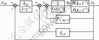
Fig. 4 SDP-PIP control implemented in feedback form
6 Controller design for LUCIE
As illustrated in Fig. 1, the LUCIE arm consists of four hydraulically actuated joints. The joint angles are measured directly by mounting rotary potentiometers concentrically with each joint pivot. Valve calibration is based on normalizing the input voltage of each joint into input demands [5]. Here, an input drive-demand of zero means no movement. Note that, without such valve calibration, the arm will gradually slack down because of the payload carried by each joint.
6.1 SDP models for joint arms
For linear PID/PIP design, open-loop step experiments are first conducted for a range of applied voltages and initial conditions, all based on a sampling rate of 0.1 s. In this case, the SRIV algorithm suggests that a first-order linear model with samples time delay ��, i.e. ![]() provides an approximate representation of each joint, with ��=1 for the dipper and bucket and ��=2 for the boom [26]. Here, yk is the joint angle and uk is the scaled drive-demand in the range ��1 000, while {a1, b��} are time-invariant parameters. a1=1 is a fixed priori in the SRIV model, so that only the numerator parameter b�� is estimated in practice for linear controllers design.
provides an approximate representation of each joint, with ��=1 for the dipper and bucket and ��=2 for the boom [26]. Here, yk is the joint angle and uk is the scaled drive-demand in the range ��1 000, while {a1, b��} are time-invariant parameters. a1=1 is a fixed priori in the SRIV model, so that only the numerator parameter b�� is estimated in practice for linear controllers design.
However, further analysis of open-loop data reveals limitations in the linear model. In particular, the value of b�� changes by a factor of ten or more, depending on the applied voltage used in experiments. In fact, SDP analysis suggests that a more appropriate model for the boom takes the form of Eq. (8) with
![]() (24)
(24)
when u��0,
![]() (25)
(25)
when u>0,
![]()
![]() (26)
(26)
and
![]()
![]() (27)
(27)
Figure 5 illustrates the parameter estimates associated with Eq. (24). These plots illustrate the meaningful state dependencies. The model and associated SDP-PIP control algorithms are updated at each sampling instant using pole assignment methods.
6.2 Implementation
Since in previous researches [5, 7-8, 26], the dipper and bucket models estimated by SRIV algorithm work well in both simulation and real machine practice, here, the models of the above two joints utilized in experiments are the same as before. However, it is noted that vibrations of the boom joint greatly influence the tracking performance of the bucket position controller, so here the SDP model of boom is utilized for improving the control performance.
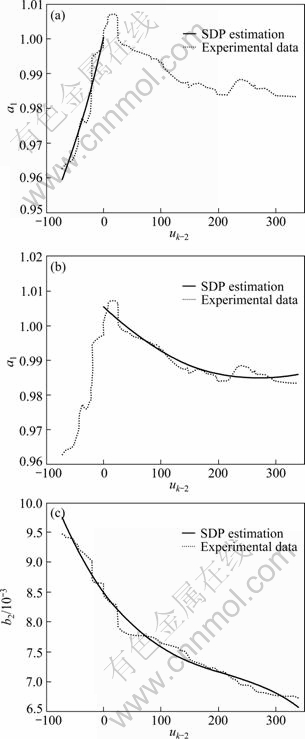
Fig. 5 SDP parameter estimates for LUCIE boom arm: (a) SDP parameter a1 estimates plotted against state variable uk-2, showing typical realization from open-loop experiment and optimized fit from datasets when uk-2��0; (b) SDP parameter a1 estimates plotted against state variable uk-2, showing typical realization from open-loop experiment and optimized fit from datasets when uk-2>0; (c) SDP parameter b2 estimates plotted against state variable uk-2,, showing typical realization from open-loop experiment and optimized fit from datasets
The PID controller gains for boom which are obtained using the Ziegler-Nichols method are 15, 10 and 5 for Kp, Ki and Kd, respectively, and the gains for boom are 20, 4 and 2 for Kp, Ki and Kd, respectively.
The fixed-PIP control algorithm for boom control case shown in Eq. (28) is based on the TF model estimated from boom closing experiment with an input drive-demand of 50. The control gain matrix applied in fixed-gain PIP controller for dipper shown in Eq. (29) is based on the TF model estimated from dipper opening experiment with an input voltage of drive-demand -100. Specify closed loop poles both at 0.60 on the real axis of the complex Z-plane:
![]() (28)
(28)
![]() (29)
(29)
The control gain matrix for SDP-PIP boom controller is updated at each sampling instant using pole assignment method.
Common tasks undertaken by an excavator include dragging the bucket in a straight line to pull soil into the bucket, and removing material from its original location and transferring it to another location to dump. In the former case, normally the bucket path is a horizontal straight line and in the latter, the bucket path is usually an oblique straight line. So, here the simulation is designed to move the bucket along a desired oblique straight line and a horizontal straight line. During the experiment, the system sample rate is 0.1 s. The simulation is based on a combination of excavator kinematics and data-based nonlinear dynamic models, implemented using the MATLAB/ SIMULINK? package, similarly as described in Ref. [5].
To demonstrate the behaviour of the proposed control schemes, consider the simulation response shown in the time series and polar coordinate plots of Figs. 6(a)-(d) and Fig. 6(e), respectively. The objective of this simulated experiment is to move the bucket from its initial position (1 378, 109) to (2 000, -600), and then to (1 000, -600), where the (x, y) coordinates are given in millimeter from the reference point.
For practical meaning, the trajectory accuracy for the control of the bucket movement along the straight lines should be no more than 100 mm and the operation time for each straight line tracking task in free motion should be less than 6 s regarding the whole digging cycle time of 15-25 s. So, in simulation, the trajectory between each set of coordinates should take the form of a 5th order polynomial jerk-free straight line as suggested by Eq. (7) and be complete in 5 s, with a wait of 0.3 s at the initial position.
To make a comparison, it shows the response of three controllers developed above. The tracking results of Fig. 6 show that the performances of PID and fix-gain PIP control are not as good as those of SDP-PIP control. Neither PID controller nor fixed-gain PIP controller, which is based on linear control methodology, has good abilities in handling nonlinear dynamic problems of hydraulic driven joint arms. It is clear from Fig. 6(e) that the bucket under SDP-PIP control is moved along the defined straight-line trajectories accurately and smoothly with the tracking error less than 20 mm for 100% within the set time.
Since the bucket position is decided by the angle of boom and dipper as described by Eqs. (1) and (2), the key to the proposed bucket position control depends on the angle control to the boom and dipper. Figures 6(a) and (b) show the tracking responses of boom and dippers respectively. It can be seen that in the first 5 s of the experiment, the movements required by set path for boom and dipper are both only in one direction (boom is kept closing while dipper is kept opening), and the tracking performance of fix-gain PIP controller is almost as good as that of SDP-PIP controller. However, in the later 5 s, when the movement of boom required by set path includes both opening and closing (the bucket is moving along horizontal path from (2 000, -600) to (1 000, -600) in this period), the tracking performance of fix-gain PIP controller becomes poor. Figure 6(a) shows that the actual path of fix-gain PIP boom controller fluctuates along the set path. This is because the control gains obtained from the boom closing model cannot work well in the boom opening case. And it is believed to be the main reason for the fluctuation of Y-coordinate position tracking responses and bucket position tracking response of fix-gain PIP controller, which is illustrated in Figs. 6(d) and (e), respectively. It is also one of the most important reasons for the failure of PID controller. As for the SDP-PIP controller, it works well in the whole experiment period since its control gains are functionally state dependent.
Furthermore, one contributing factor for the failure of the PID approach is the time delay between the application of a drive-demand and movement of the joints. Indeed, control of integrators with time delay is a rather difficult control problem in general. This is one reason why the author has turned to the more sophisticated PIP approach, which is able to handle time delays automatically [27].
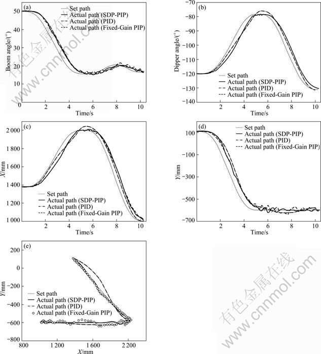
Fig. 6 Simulation of bucket movement along specified straight lines, comparing SDP-PIP, fixed-gain PIP, PID and set path: (a) Boom angle tracking response; (b) Dipper angle tracking responses; (c) X-coordinate position tracking responses; (d) Y-coordinate position tracking responses; (e) Bucket position tracking response in polar coordinate
7 Conclusions
1) The control of a hydraulic robotic excavator is described. The excavator arm represents a difficult control problem due to both the plant nonlinearity and the demanding design specifications. Linear and nonlinear approaches have been evaluated for joint arms control, including PID control tuned by conventional Ziegler-Nichols rules, linear PIP control, and a novel, nonlinear PIP design based on the identification of SDP models.
2) The boom is modelled using the SDP model structure, in which the parameters are functionally dependent on other variables in the system. This formulation is subsequently used to design an SDP-PIP control algorithm, in which the control gains are themselves state dependent. In simulation, the bucket moves along the specified straight lines which are often employed in real digging process.
3) Compared with PID and fixed-gain PIP controllers, SDP-PIP controller provides an improved performance with higher accuracy and smoother track.
Acknowledgments
Many thanks to Dr. James Taylor (Lancaster University) for his help in CPATAIN Toolbox.
References
[1] MERRITT E. Hydraulic control systems [M]. New York: John Wiley, 1976.
[2] Chiang M H, Murrenhoff H. Adaptive servo-control for hydraulic excavators [C]// Power Transmission and Motion Control [PTMC�� 98]. UK: Professional Engineering Publishing Limited London and Bury St Edmunds, 1998: 81-95.
[3] Ha Q, Nguyen Q, Rye D, DURRANT-WHYTE H. Impedance control of a hydraulic actuated robotic excavator [J]. Journal of Automation in Construction, 2000, 9(5/6): 421-435.
[4] BUDNY E, CHLOSTA M, GUTKOWSKI W. Load-independent control of a hydraulic excavator [J]. Journal of Automation in Construction, 2003, 12(3): 245-254.
[5] GU J, TAYLOR C J, SEWARD D. Proportional-integral-plus control of an intelligent excavator [J]. Journal of Computer-Aided Civil and Infrastructure Engineering, 2004 19(1): 16-27.
[6] TAYLOR C J, SHABAN E M, STABLES, M A, AKO S. Proportional-integral-plus control applications of state-dependent parameter models [J]. IMECHE Proceedings Journal of Systems and Control Engineering, 2007, 221(17): 1019-1032.
[7] GU J, SEWARD D. Digital servo control of a robotic excavator [J]. Chinese Journal of Mechanical Engineering, 2009, 22(2): 190-197.
[8] GU J, SEWARD D. Improved control of an intelligent excavator using proportional-integral-plus (pip) gain scheduling [J]. Journal of Central South University of Technology, 2012, 19(2): 384-392.
[9] BRADLEY D A, SEWARD D W. The development, control and operation of an autonomous robotic excavator [J]. Journal of Intelligent and Robotic Systems, 1998, 21(1): 73-97.
[10] YOUNG P C, BEHZADI M A, WANG C L, CHOTAI A. Direct digital and adaptive control by input-output, state variable feedback pole assignment [J]. International Journal of Control, 1987, 46(6): 1861-1881.
[11] Taylor C J, Chotai A, Young P C. State space control system design based on non-minimal state-variable feedback: Further generalisation and unification results [J]. International Journal of Control, 2000, 73(14): 1329-1345.
[12] YOUNG P C. FITZGERALD W J, ed. Stochastic, dynamic modelling and signal processing: Time variable and state dependent parameter estimation��s nonlinear and nonstationary signal processing [M]. Cambridge: Cambridge University Press, 2000.
[13] Seward D W, Pace C and Agate R. Safe and effective navigation of autonomous robots in hazardous environments [J]. Autonomous Robots, 2007, 22(3): 223-242.
[14] FRANKLIN G F, POWELL J D, EMAMI-NAEINI A. Feedback control of dynamic systems, 3rd ed [M]. Reading, MA: Addison Wesley, 1994.
[15] CHOTAI A, YOUNG P C, BEHZADI M A. Self-adaptive design of a nonlinear temperature control system [J]. Special Issue on Self-tuning Control, IEE proceedings, Part D, 1991, 38: 41-49.
[16] Taylor C J. Generalized proportional-integral-plus (PIP) control [D]. Lancaster: Lancaster University, 1996.
[17] TAYLOR C J, CHOTAI A, YOUNG P C. Nonlinear control by input-output state variable feedback pole assignment [J]. International Journal of Control, 2009, 82(6): 1029-1044.
[18] EXADAKTYLOS V, TAYLOR C J, WANG L, YOUNG P C. Forward path model predictive control using a non-minimal state space form [J]. IMECHE Proceedings Journal of Systems and Control, 2009, 223(3): 353-369.
[19] WANG L, GAWTHROP P, YOUNG P C, TAYLOR C J. Non-minimal state space model-based continuous-time model predictive control with constraints [J]. International Journal of Control, 2009, 82(6): 1122-1137.
[20] SHABAN E M, AKO S, TAYLOR C J, SEWARD D W. Development of an automated verticality alignment system for a vibro-lance [J]. Automation in Construction, 2008, 17(5): 645-655.
[21] TAYLOR C J, PEDREGAL D J, YOUNG P C, TYCH W. Environmental time series analysis and forecasting with the captain toolbox [J]. Environmental Modelling and Software, 2007, 22(6): 797-814.
[22] STABLES M A, TAYLOR C J. Nonlinear control of ventilation rate using state dependent parameter models [J]. Biosystems Engineering, 2006, 95(1): 7-18.
[23] McCABE A P, YOUNG P C, CHOTAI A, TAYLOR C J. Proportional-Integral-Plus (PIP) control of non-linear systems [J]. Systems Science, 2000, 26(1): 25-46.
[24] BURNHAM K J, DUNOYER A, MACROFT S. Bilinear controller with PID structure [J]. IEEE Computing and Control. Engineering Journal, 1999, 10(2): 63-69.
[25] ZIEMIAN S J. Bilinear proportional-integral-plus control [D]. Coventry University, UK, 2002.
[26] Gu J, Taylor C J, Seward D. Modelling of an hydraulic excavator using simplified refined instrumental variable (SRIV) algorithm [J]. Journal of Control Theory and Applications, 2007, 5(4): 391-396.
[27] TAYLOR C J, CHOTAI A, YOUNG P C. Proportional-Integral- Plus (PIP) control of time delay systems [J]. Proceedings of the Institute of Mechanical Engineering, Journal of Systems and Control Engineering, 1998, 212(1): 37-48.
(Edited by YANG Bing)
Foundation item: Work supported by the Lancaster University, UK and Jiangsu Provincial Laboratory of Advanced Robotics, SooChow University, China; Project(BK2009509) supported by the Natural Science Foundation of Jiangsu Province, China; Project(K5117827) supported by the Scientific Research Foundation for the Returned Scholars, Ministry of Education of China; Project(Q3117918) supported by the Scientific Research Foundation for Young Teachers of Soochow University, China
Received date: 2011-05-31; Accepted date: 2011-10-08
Corresponding author: GU Jun, Associated Professor, PhD; Tel: +86-512-67165607; E-mail: gujun@suda.edu.cn
Abstract: Various control systems for a robotic excavator named LUCIE (Lancaster University Computerized and Intelligent Excavator), were investigated. The excavator is being developed to dig trenches autonomously. One stumbling block is the achievement of adequate, accurate, quick and smooth movement under automatic control. Here, both classical and modern approaches are considered, including proportional-integral-derivative (PID) control tuned by conventional Zigler-Nichols rules, linear proportional-integral-plus (PIP) control, and a novel nonlinear PIP controller based on a state-dependent parameter (SDP) model structure, in which the parameters are functionally dependent on other variables in the system. Implementation results for the excavator joint arms control demonstrate that SDP-PIP controller provides the improved performance with fast, smooth and accurate response in comparison with both PID and linearized PIP control.
