
���±��: 1004-0609(2005)12-1992-06
��������������Ͻ�ܲļ�ѹ���̵���ֵģ��
̷��ǿ1, 2, ������2, Ф�ڵ�2, �ƽ���1, �� ��2, ��ӭԪ3
(1. �ϲ���ѧ ���Ͽ�ѧ�빤��ѧԺ, �ϲ� 330047; 2. ���ϴ�ѧ ���Ͽ�ѧ�빤��ѧԺ, ��ɳ 410083;
3. �й������ܹ�˾725��, ���� 315103)
ժ Ҫ��
����DEFORM����Ԫ�����о��˷����ܴ�����������������Ͻ�ܲļ�ѹ�Ʊ����⾶Ϊ417mm�� �ھ�Ϊ340mm�ܲĵı��ι���, ��ģ���˼�ѹ������Ӧ������ Ӧ�䳡�� ���ܶ��Լ���ѹ���ı仯����� ģ��������: ��ѹ����Ϊѹʵ��, ��ѹ�����ӻ���; ���ż�ѹ���̵IJ��Ͻ���, �Ӽ�ѹβ������ѹͷ��, ���������ܶȳʽ���ʽ����, ��ЧӦ�䡢 Ӧ����Ӧ�����ʵı仯���������ܶ�������; �ڼ�ѹ������Ӧ�䡢 Ӧ����Ӧ�����ʱ仯����; ��ѹ��Ĺܲ�Ϊ���ܲ���, ���ѹ��Ϊ6.45��104 kN, ��ʵ�ʼ�ѹ�����м�ѹ�������ܶ���Ƚ�, �����ģ������ʵ�������������
�ؼ���: �������Ͻ�; �����ܲ���; ���±���; ��ֵģ��; ������� ��ͼ�����: TG376
���ױ�ʶ��: A
Numerical simulation of direct extrusion process for preparing spray deposition pipe of heat-resistant aluminium alloy
TAN Dun-qiang1, 2, LI Wen-xian2, XIAO Yu-de2, TANG Jian-cheng1,
ZHOU Lang2, ZHANG Ying-yuan3
(1. School of Materials Science and Engineering,
Nanchang University, Nanchang 330047, China;
2. School of Materials Science and Engineering,
Central South University, Changsha 410083, China;
3. 725 Institute of China Shipping Company, Nuoyang 315103, China)
Abstract: The extrusion process of preparing pipe with external diameter of 417mm and inner diameter of 340mm by spray deposition pipe of heat-resistant aluminum alloy through the finite element software DEFORM. The field of stress, strain, density and the extrusion force during extrusion process were analyzed. The results of numerical simulation show that the extrusion force increases laxly at first step of extrusion process. During the extrusion process, the distribution of density increases step by step from the end to the head of ingot, and the distributions rule of strain, stress and strain rate are similarity to that of density. In the field of extrusion distortion, the changes of strain, stress and strain rate are very sharply. The experimental pipe after extrusion is compact material, and the experimental maximum extrusion force is 6.45��104 kN. Compared the maximum of extrusion force with the density of extrusion pipe, the simulation results agree with the experiment results.
Key words: heat-resistant aluminum alloy; porous material; high temperature deformation; numerical simulation; spray deposition
����������Ʊ���ߴ�������̲��ϳ��õ�һ�ֹ���, ��������������д�����, ����֮�䡢 ����������֮���δ�ﵽ��ȫ��ұ����, ֱ��ʹ�����ܽϲ�, ��˱���Գ������Ͻ�����Ч���ȼӹ�ʹ�����ܻ��� ͬ��, �������Al-Fe-V-Si�������Ͻ�����ܻ����Ʊ�����ṹ���Ĺؼ�Ҳ���ѵ�[1-3]�� һ����, �ھ������ʱ�辡���ܵ�ѡ��ϵ͵ij����¶Ⱥͽ϶̵ļ���ʱ����ά�ֿ������̵���֯����; ��һ����, Ҫ�����ʱ������������ܹ��õ���ֱ���, ͬʱ�ڼ���Ӧ���²����㹻�ļ��б�����ʵ��������ұ����, ȷ������������ȫ���ܻ�, ���ӿ��������������Ͻ�ı������ܡ�
�����ܲ����ڲ����д����Ŀ�϶, �����Ա���ʱ���������ѹ���ԡ� ���������ԡ� С�������������κ����ܲ����ȵ��ص�, ����ι��ɽ����ܲ��ϸ���[4-8]�� �����ܲ��ϵ�����Ԫģ�������Ч�ؽ�ʾ�����������ɺ����ܹ���[9-14]�� �ڶԱ��ι��̽�������Ԫ����ʱ, ���ø����Ժ�ճ������Ԫ��[15, 16], �������Ա��κ��ԡ� ����������Ԫ�����Ʋ��ϵ��Ա���, ������������������ֱ�ӵõ��ٶ�����, �ܿ��˼��η���������, ����ڼ���������������ȡ�ýϴ�, ������С�Ҿ��Ƚϸ�, �ʺ�ģ�⸴�ӵĴ���ι��̡� �������߲��ÿ�ѹ���Եĸ���������Ԫ������ʵ����ֵģ�⡣
����DEFORM����Ԫ����������ѹ���⾶Ϊ417mm�� �ھ�Ϊ340mm�ĹܲĽ�����ֵģ��, �����˼�ѹ������Ӧ������ Ӧ�䳡�� ���ܶ��Լ���ѹ���ı仯���, ΪAl-Fe-V-Si�Ͻ�Ĵ��ͷ����ܹ��������ṩ������IJο���
1 ʵ��
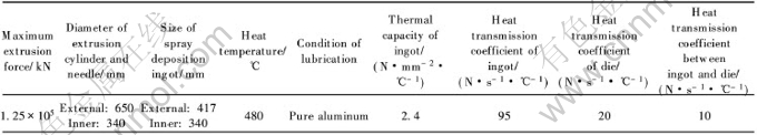
Ħ������ʵ�顢 ��Ӧ������Ӧ��Ĺ�ϵ������Gleeble1500��ģ��������, ���ι���ȫ���ɼ�������Ʋ��Զ��ɼ�ʵ�����ݡ� ������Ӧ��ģ�ͼ���DEFORM����Ԫ����, �����ڸ����ı���״̬�����µ�����Ӧ�������ݵ����ʽ����������, DEFORM����Ԫ���������������������Զ���ֵ���㡣 ��Ħ��ģ�ͼ���DEFORM����Ԫ�������ǽ��ڸ����ı���״̬�����µ�Ħ�����������ݵ����ʽ���������� �ڽ�����ģ�����ʱ, ģ�Ǿ�Ϊ90��(ƽģ��ѹ), ģ���ʵ���Բ��, �����������ڱ�1�С�
��������������Ͻ�ɷ�ΪAl-(8.4%~8.7%)Fe-(1.1%~1.4%)V-(1.4%~1.7%)Si(��������), ��ʼ���ܶ�Ϊ90%�� ��ѹʱ����������3�����մ�ʩ: ��������ͷϳ��, ����������, ����20mm������; ����װ�뼷ѹͲ��ֹ����������λ, ǰ��������ӹ����Ϊ10mm, �⾶Ϊ650mm, �ھ�Ϊ360mm�������� �������ڲ���ʽ����¯�н��е��³�ʱ�����¶�ʱ�ķּ�����: 400��, 6h[FY]450��, 4h[FY]480��, 2h�� ��ѹͲ�����ϵļ����¶���ͬ; ��ѹ�롢 ģ�ߺ������ļ����¶�Ϊ380~400�档
2 ����Al-Fe-V-Si�������Ͻ�ѹ���ι��̵���ֵģ��
2.1 �����ڱ��ι����е����ܶȱ仯
ͼ1��ʾΪ�����������������ѹ���ι��������ܶȵı仯�� ��ͼ1�ɿ���, ���ε�20��ʱ, ��������������ܶ���ͬ, �ȳ�ʼ���ܶ��������; �����ε�60��ʱ, ������ͷ�������������ܶ����Ѹ��, �ںͼ�ѹ��Ӵ��������γɼ�ѹʱ����������, ����β�������ܶȳʽ��ݱ仯; �����ε�84��ʱ, ���������ܶȴ�β����ͷ�����, �γ����ԵĽ���״�ֲ�, ��ģ�ڸ������ܶȱ仯����; �����ε�142��ʱ, ��β����ͷ���������ܶȵı仯��η���, ��ѹ�����Ĺܲ����ܶȴﵽ0.9985, �ѳ�Ϊ���ܲ���; �ڼ�ѹ�����������ܶ�û��̫��仯��
��1 ��ֵģ���ʵ����̵Ļ�������
Table 1 Parameters of numerical simulation and experiment process
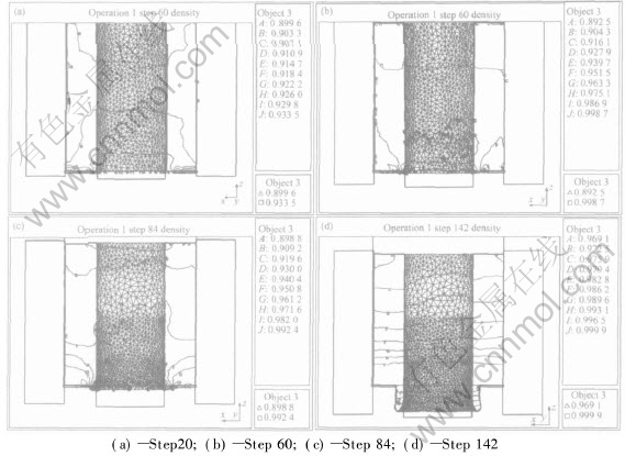
ͼ1 ��ѹ���������ܶȵı仯(����������ϳ�ʼ���ܶ�Ϊ90%)
Fig.1 Variation of density during extrusion process
(Initial density of spray deposition ingots is 90%)
2.2 �����ڱ��ι����еĵ�ЧӦ�䡢 Ӧ����Ӧ���ʵı仯
ͼ2~4��ʾΪ���ι����е�ЧӦ���� ��ЧӦ�����ʺ͵�ЧӦ���ķֲ��ı仯�� ��ͼ2~4�пɿ���, ��ЧӦ�����ų�ʼ����ܶȵ��������С, �ҵ�ЧӦ�����ֵ��С; ���ż�ѹ���̵Ľ���, ��ЧӦ����������ܶȵ����Ӷ�����, Խ������ģ����һ��, ���ֱ仯Խ���ҡ� �ڼ�ѹ�Ƚ��ȶ��Ľ�(����ε�142��), ��ЧӦ�����ʱ仯����, Ҳ�ڿ���ģ�ڸ�����
��ģ�ں������Ϸ��ļ�ѹͲ�ڸ�����������Ӧ������(��ͼ4), ��������ģ�ڸ�������ѹͲ�ڸ����Ľ������ܽϴ�ļ��б���, �ӹ�����β����ͷ��, Ӧ���������ӡ�
2.3 �����ڱ��ι����м�ѹ���ı仯
ͼ5��ʾΪ���ι����еļ�ѹ����ʱ��ı仯���ߡ� ��ͼ5�ɿ���, ����ѹ����������, ��ѹ��Ҳ��֮���ӡ� ���ڼ�ѹ��ʼ��, ��ѹ��������Ҫ������ѹʵ���ܶ�����, ��ѹ���ı仯��Ϊ����; ���, ��ѹ���������ٶ���������, ��ijһʱ�̴ﵽ�ȶ�״̬��
3 ����
���������������Ϊ�����ܲ���, ��������������ζ���, ������������ܶȵı仯��Ϊ��Ҫ, �ɷ����ܻ������Ͼ����κ��Ϊ���ܻ����ϡ� �������ܶȱ仯����Ҫԭ��Ϊ��ˮӦ���ͼ������� �ڼ�ѹ�տ�ʼʱ, �����ܲ������ܶ���ƽ��Ӧ���������й�ϵ, ��ƽ��Ӧ��ʹ����ܶȽ���, ��϶������, ���γ����Ƶȡ� ��ƽ��Ӧ��(��ˮӦ��)����������ܶȵ����, �Ҿ�ˮӦ��Խ��, ���ܶ�ҲԽ�ߡ� �ڼ�ѹ����, ����������Ȼ������ܵ���ˮѹ������, ���������������������, һЩ�������߲���Ĵ�С�� ��״��������, ���ѱ�֤�䱣�־�ˮѹ״̬, ���ʹ��Щ��������淢����״�仯����ת��, �����Ա���, ���κ�Ŀ���ռ���˿����䡢 ����������ȵĿ�϶, ʵ��ѹʵ����, ���ں�������������Ա���, ��ֻ����Ϊѹʵ����, ����ڹ����Ĵ��������ܶȱ���һ��(��ͼ1(a)), �Ҽ�ѹ���ı仯Ҳ����
���ż�ѹ�Ľ�һ������, ������ͷ������ֱ�����ϱ�����ģǻ, ���������б���, �Ӷ����м�����������, ���������ܶ����Ѹ�١� ��������������ģǻʱ, ���ܶ����ž�ˮѹ���ķֲ��Ӽ�ѹβ����ͷ����������, Խ����ѹͷ�������ӿ�, ��ѹ���ı仯����Ҳͬ���ӿ졣 ���Ͻ��뼷ѹ�����������ڼ�ѹ��������ʱ, �����Ա���Ϊ��, һЩ��ĩ���������������䷢���Ħ���� ����, �ر����ڼ�ѹģ�ڴ�, ��������������ܶ�����߷������ ͬʱ, �ںͼ�ѹģ�߽Ӵ����ֵľ�ˮѹ��Ҳ��������, �������������ܶ����, ��ʱ����ͷ���ļ�ѹ�������ܲ��ϵļ�ѹ�� ����ѹ���̱Ƚ��ȶ�ʱ, �����е����ܶ��й��ɵشӼ�ѹͷ������ѹβ��ƽ������(��ͼ1(d))��

ͼ2 ��ѹ�����е�ЧӦ��ı仯
Fig.2 Variations of strain during extrusion process
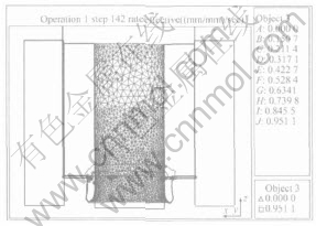
ͼ3 ����142��ʱ��ѹ������Ӧ�����ʳ�
Fig.3 Strain rate field during extrusion process at step 142
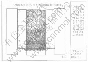
ͼ4 ����98��ʱ��ѹ������Ӧ����
Fig.4 Stress field during extrusion process at step 98
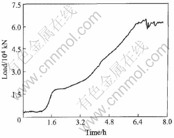
ͼ5 ��ѹ�����м�ѹ����ʱ��ı仯����
Fig.5 Change curve of extrusion force with time during extrusion process
���ݷ����ܲ��ϵ��������ۿ�֪, �����ܲ��ϵĵ�ЧӦ��ȡ����Ӧ��ƫ����Ӧ��������������, �����Ա��κ����Ӧ�䡣 �ڼ�ѹ����, �ر��ǿ�����ѹ��ģ������, ������ѹʵ����Ϊ��, ��ײ��ϵĵ�ЧӦ����Ҫȡ����Ӧ��������, ������ܶ�Խ��, ���Ӧ��ҲԽ�� ���, ����һ��, ��ЧӦ����������ܶȵ����߶�����, �����Ӧ�����ֵ��С, ���Ӧ�ĵ�ЧӦ����ֵҲ��С�� ���ż�ѹ�ļ���, ���Ͻ��뼷ѹ�����������ڼ�ѹ�������ڵIJ��������Ա���Ϊ��, Ӧ��ƫ������ֵ�ϴ��Ӧ��������ʱ, ��ʱ�ĵ�ЧӦ����Ҫȡ����Ӧ��ƫ���� ����ܶ�Խ��, �������Ա���Խ��, ��ЧӦ��ҲԽ��, ��ģ�ڸ����仯���ҡ�
��������ģ��, ��������Ӧ�����ʱ仯����(��ͼ3)�� �����ڲ����ⲿ����������������������, ����������������ģ��������Ʒ����������������Ʒ������, ������һ������ϵĽ����ʵ����һ�����ٶȽ���������� һ����Ϊ��������ģ��������̬���νΡ� �ڴ˽�, Ӱ�켷ѹ���仯����Ҫ����Ϊ���ι����е��¶ȱ仯�� �¶ȱ仯�Լ�ѹ����Ӱ�����������: һ����, �¶�����ʹ����������Ӧ���½�, �Ӷ����¼�ѹ������; ��һ����, �����¶ȵ�����ʹ����������(��ͼ2), ������ЧӦ�������빤����ȴ���, ������������, �Ӷ����¼�ѹ�����ߡ� ��ʵ��ģ����¶ȼ�ѹ����ЧӦ��̫����(��ͼ6), �����뼷ѹģ��(�¶�Ϊ400��)�������й���, ��������ģ����õı߽������й�ϵ�� ����ģ����ε����½�С, �������ȱ�������������ȶ���, ��ѹ����֮�ȶ���
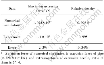
ͼ7��ʾΪʵ���Ʊ��⾶Ϊ417mm, �ھ�Ϊ340mm, ����Ϊ3m������ѹ�ܡ� ����ģ������������Ҫ����������: 1) ģ�����õ��ļ�ѹ����ʵ�ʵļ�ѹ���ıȽ�; 2) ģ�����ļ�ѹ����ܲ����ܶ���ʵ�ʼ�ѹ�ܲ����ܶȵıȽϡ� ��2����Ϊģ���������ʵ����ıȽ�, ����ѹ�ܲĵļ�ѹ��ģ�����ֵ��ʵ��ֵ���2.3%, ��ʵ��ѹ���Ĺܲ����ܶȾ��ӽ���1, ���ģ������������ �ɼ�����ʵ���ģ���������ʵ�ط�ӳ�˴���ѹ�ܲļ�ѹ���̵ı仯�����
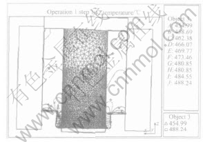
ͼ6 ����142��ʱ��ѹ�����е��¶ȳ�
Fig.6 Temperature field during extrusion process at step 142
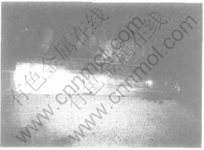
ͼ7 �⾶Ϊ417mm, �ھ�Ϊ340mm,����Ϊ3m��ѹ�ܵ���Ƭ
Fig.7 Photo of extrusion pipe with external diameter of 417mm, inner
diameter of 340mm and length of 3m
��2 ��ֵģ������ʵ�����ıȽ�
Table 2 Comparison between results of numerical simulation and experiment
4 ����
1) ģ�⼷ѹ����Ϊѹʵ��, ��ѹ���������ӡ� ����ģ�⼷ѹ���̵IJ��Ͻ���, ��β����ͷ, ���������ܶȳʽ���ʽ����, ��ЧӦ�䡢 Ӧ����Ӧ�����ʵı仯���������ܶȵı仯�������ơ�
2) �ڼ�ѹ������, ���ܶȡ� Ӧ�䡢 Ӧ����Ӧ���ʱ仯����, ģ�⼷ѹ��ܲ�Ϊ���ܲ���, ���ѹ��Ϊ6.45��104 kN��
3) ��ʵ�ʼ�ѹ�����еļ�ѹ�������ܶȴ�С��Ƚ�, �����ģ������ʵ�������������
REFERENCES
[1]TAN Dun-qiang, LI Wen-xian, XIAO Yu-de, et al. Phase transition of AlFeVSi heat resistant alloy by spray deposition[J]. Trans Nonferrous Soc China, 2003, 13(3): 568-573.
[2]Santosh K D. Rapid solidification and powder metallurgy at allied-signal Inc[J]. Int J Powder Metall, 1992, 24(2): 175-183
[3]Singer A R E. Recent developments in the spray forming of metals[J]. Powder Metall, 1985, 21(3): 219-225
[4]�����, ��ѧƽ. ��ѹ�����ϼ�ѹ��������Ԫģ��[J]. �������ι���, 2001, 19(3): 4-8.
HOU Hong-liang, REN Xue-ping. Finite element simulation to extrusion process for compressible materials[J]. Metal Forming Technology, 2001, 19(3): 4-8.
[5]�����, ������, ������. ��ײ��ϼ�ѹ������ֵģ��[J]. �������칤ҵѧԺѧ��, 2000, 10(2): 5-9.
HOU Hong-liang, JIAO Man-dun, MI Xin-lan. Simulation of extrusion for porous material[J]. J North China Institute of Astronautic Engineering, 2000, 10(2): 5-9.
[6]YANG Zheng-wei. Perturbation analysis of extrusion of porous metal materials[J]. Appl Math Modeling, 1995, 19(10): 601-612.
[7]Yang Z W, Lippmann H. Asymptotic analysis of extrusion process through tapering die[J]. Int J Mach Tools Manufact, 1995, 35(11): 1587-1601.
[8]Yang Z W, Lippmann H. A study of sintered powder metals[J]. Int J Mech Sci, 1996, 38(1): 79-96.
[9]Parteder E, Riedel H, Sun D Z. Simulation of hot forming processes of refractory metals using porous metal plasticity models[J]. Int J Refractory Metals & Hard Materials, 2002, 20: 287-293.
[10]Boomsma K, Poulikakos D, Ventikos Y. Simulations of flow through open cell metal foams using an idealized periodic cell structure[J]. Int J Heat and Fluid Flow, 2003, 24: 825-834.
[11]Siruguet K, Leblond J B. Effect of void locking by inclusions upon the plastic behavior of porous ductile solids����: theoretical modeling and numerical study of void growth[J]. Int J Plasticity, 2004, 20: 225-254.
[12]Parteder E, Riedel H, Kopp R. Densification of sintered molybdenum during hot upsetting: experiments and modeling[J]. Mater Sci and Eng A, 1999, 264: 17-25.
[13]Armero F, Oller S. A general framework for continuum damage models(��)��Innitesimal plastic damage models in stress space[J]. Int J Solids and Structures, 2000, 37: 7409-7436.
[14]Armero F, Oller S. A general framework for continuum damage models(��)��Integration algorithms with applications to the numerical simulation of porous metals[J]. Int J Solids and Structures, 2000, 37: 7437-7464.
[15]�ܷ�, ��ӱ��, ��ѩ��. ���Ͳļ�ѹ��������Ԫ��ֵģ��[J]. �й���ɫ����ѧ��, 1998, 8(4): 637-642.
ZHOU Fei, PENG Ying-hong, RUAN Xue-yu. Numerical simulation of aluminium material extrusion process by finite element method[J]. The Chinese Journal of Nonferrous Metals, 1998, 8(4): 637-642.
[16]�ܷ�, �յ�, ��ӱ��, ��. ���������ģ�����Ͳļ�ѹ���ι���[J]. �й���ɫ����ѧ��, 2003, 13(1): 66-70.
ZHOU Fei, SU Dan, PENG Ying-hong, et al. Simulation of aluminum material extrusion process with finite volume method[J]. The Chinese Journal of Nonferrous Metals, 2003, 13(1): 66-70.
������Ŀ: �����ص�����о���չ�滮������Ŀ(G1999064900)
�ո�����: 2005-09-05; ������: 2005-06-20
�����: ̷��ǿ(1975-), ��, ������, ��ʿ
ͨѶ����: ̷��ǿ, ��ʿ; �绰: 0791-6053179; E-mail: tdunqiang@sohu.com
[4]�����, ��ѧƽ. ��ѹ�����ϼ�ѹ��������Ԫģ��[J]. �������ι���, 2001, 19(3): 4-8.
[5]�����, ������, ������. ��ײ��ϼ�ѹ������ֵģ��[J]. �������칤ҵѧԺѧ��, 2000, 10(2): 5-9.
[8]Yang Z W, Lippmann H. A study of sintered powder metals[J]. Int J Mech Sci, 1996, 38(1): 79-96.
[15]�ܷ�, ��ӱ��, ��ѩ��. ���Ͳļ�ѹ��������Ԫ��ֵģ��[J]. �й���ɫ����ѧ��, 1998, 8(4): 637-642.
[16]�ܷ�, �յ�, ��ӱ��, ��. ���������ģ�����Ͳļ�ѹ���ι���[J]. �й���ɫ����ѧ��, 2003, 13(1): 66-70.
