
Trans. Nonferrous Met. Soc. China 30(2020) 2090-2106
Strain anisotropy models for refined diffraction line profile analysis in cubic metals
Xiang DAI1, Fu-lin JIANG1,2, Jin LIU1, Luo-yi WU1, Ding-fa FU1, Jie TENG1, Hui ZHANG1
1. College of Materials Science and Engineering, Hunan University, Changsha 410082, China;
2. Research Center for Steel, Kyushu University, 744 Motooka Nishi-ku, Fukuoka 819-0395, Japan
Received 11 January 2020; accepted 16 June 2020
Abstract:
The present work examined the anisotropy magnitudes obtained from different elastic models of cubic metals (Cu, 5383 Al alloy, FCC austenite steel and BCC steel) to explore the origin of strain anisotropy. The results showed that stable intersections were observed from the modeled and experimental plots of the reciprocal elastic modulus (1/Ehkl) and orientation parameter (��). The effectiveness of quasi elasto-plastic model based method in correcting strain anisotropy was further verified in cold-worked specimens. For the important input parameters in dislocation model based diffraction line profile analysis methods, the average diffraction contrast factors  of dislocations were observed to depend on elastic constants. Interesting intersections were found from linear dependence of
  on ��. The conventional input
  values indicated distinct dependencies on given elastic constants in diffraction line profile analysis. Accordingly, a refined approach was proposed by adopting the optimized intersections as input values, by which more reliable results could be obtained in practical applications.
Key words:
metallic materials; line profile analysis; strain anisotropy; dislocation;
1 Introduction
Metals are important materials in modern manufacturing and products. When a metal is plastically deformed, dislocations move and additional dislocations are gradually generated. Then, the resulted work hardening (or strain hardening) makes the metal harder and stronger due to the accumulation of dislocations. When high dislocation density is presented in a metal, the dislocations interact and become pinned or tangled strongly, which affects the properties of strength, fracture, fatigue, etc [1-4]. Hence, the in-depth understanding of work hardening and dislocation strengthening mechanisms is of vital importance for the processing optimization and alloy designing in high performance materials. To achieve these efforts, the experimental knowledge of plastic lattice strain, cell structure, dislocation density and characteristics is essential, for instance, the classical Taylor hardening law accounting for dislocation strengthening [1] and the modified two-phase composite model for heterogeneously distributed dislocation systems [5].
X-ray (or synchrotron radiation or neutron) diffraction line profile analysis (LPA) is one of the most effective methods for quantitatively or semi- quantitatively estimating microstrain, dislocation density, crystal/dislocation-cell size, planar fault percentage and the dislocation slip systems presented in samples that are either practically very difficult or not possible to use other techniques [4,6-10]. For instance, it has been confirmed that LPA provided dislocation densities in a statistically significant manner with higher accuracy than transmission electron microscopy (TEM) [4,9,10]. And TEM method normally provides quantified results around a limited dislocation density magnitude of 1014 m-2 [4,7,10]. However, the anisotropic peak broadening resulted from strain anisotropy, which is a well-known phenomenon in LPA or Rietveld structure refinement, leads to non-monotonous functions between the full width at half-maximum (FWHM) (or integral breadth or Fourier coefficients) of diffraction profiles and the diffraction vector or its square, g or g2 [7]. Therefore, the correction of strain anisotropy is crucial for improving the data analysis and reducing errors. Numerous approaches have been developed to deal with the strain anisotropy in metallic materials [4,6-10].
Based on a model of which peak broadening was attributed to distortions within a crystal, STOKES and WILSON [11] derived a formula for microstrain (��hkl or mean square strain  [6]) broadening that could explain the observed peak broadening anisotropy. The stress distribution for Laue breadth was assumed to be statistically isotropic, and then the elastically anisotropic crystals would lead to a strain that varied with crystallographic direction [9]. Following this concept, a quasi elasto-plastic model based LPA approach has been developed by JIANG et al [8] recently to reliably assess the strain anisotropy. It was known that the magnitude of mirostrain could be quantitatively related to the lattice distortion, i.e., the mean displacement from idea atomic position or the mean strain field of long-range dislocations. As a result, the strain anisotropy was also derived in terms of the presence of dislocations, which was well known as dislocation model of strain anisotropy [4,6,7]. In this model, the mean square strain was employed through renormalizing the crystal size by the effective outer cut-off radius (Re) of dislocations, and the contrast factor (C) of dislocations or dislocation-like lattice defects was introduced to correct the strain anisotropy [7,12]. However, there are still problems in determining the approach to utilize and the potential errors. In the present work, the elastic anisotropy and origin of strain anisotropy in various cubic metals, i.e., nickel (Ni), copper (Cu), aluminum (Al), face-centered cubic (FCC) steels and body centered cubic (BCC) steels, were discussed by comparing numerous simulated and measured results. The effectiveness of quasi elasto-plastic model based LPA approach [8] was further verified experimentally for strain anisotropy correction. Then, the theoretical values of average diffraction contrast factor
  in dislocation model were summarized based on ANIZC program in different cubic metals. The effects of elastic constants from various references on the linear dependence of with orientation parameter �� were investigated. After that, refined line profile analysis approaches on the basis of mWH/mWA and CMWP methods were proposed and further examined by experimental results. By overcoming the unfavorable effects from fluctuant
  values, the refined approaches could adaptively lead to more reliable results of both dislocation density (��) and dislocation arrangement parameter (M) in practical applications.
2 Experimental
The well-annealed (WA) pure Cu, 5383 Al alloy, SUS316L austenitic steel [13] and 0.0056% C (mass fraction) ferritic steel [14], with electron backscattered diffraction (EBSD) microstructures shown in Figs. 1(a-d), were cold deformed by unidirectional rolling (UDR) to various reductions, respectively. To tailor different microstructures, the commercial pure Ni plates with a thickness of 5 mm were reduced to thicknesses from 1 to 2.5 mm by combining hot rolling and finished 50% cold rolling reduction [8]. Then, the specimens were well annealed at 800 ��C for 3.6 ks to eliminate residual plastic lattice distortions and texture, as presented in Fig. 1(e). It is reported that the changes of cold-worked strain paths could lead to various slip behaviors (dislocations) and textures [8,15,16]. Hence, the WA specimens were cold worked (ambient temperature) to a thickness of 1 mm by UDR and multi-step cross rolling (MSCR), respectively, which obtained various true strains (��T) from 0 to 0.92. Further, the WA specimens were also cold worked by uniaxial tensile testing (UTT), which owned a maximum true strain approximately 0.36 before clear necking. X-ray diffraction (XRD) experiments were carried out on the deformed specimens by utilizing an X-ray diffractometer (RINT2100, Rigaku Co., Ltd.) equipped with a Cu K�� radiation source (40 kV, 40 mA) after removing the surface layers of measured specimens [7,8,17]. The step size was 0.02�� and the counting time was 1.5 s. For LPA, a special program was developed to fit every peak by Voigt function. Meanwhile, the instrumental effects were eliminated by utilizing the diffraction pattern of the NIST SRM 660c LaB6 standard powder [8,18]. The micro textures of Ni were examined by EBSD and the dislocation characteristics were also observed under TEM.
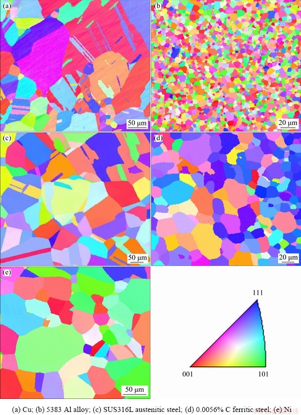
Fig. 1 EBSD microstructures of different well-annealed samples
3 Results and discussion
3.1 Elastic and plastic strain anisotropy in cubic metals
In the case of classical Voigt model, all grains in the polycrystalline aggregate employ strain tensors that are equal to the macroscopic strain tensor, i.e.,  . As a result, an isotropic tensor is yielded, and the inverse elastic modulus (1/Ehkl) in cubic crystals can be derived as follows [19-21]:
 (1)
(1)
where S11, S12 and S44 are elastic parameters. In general, Voigt model represents the upper limits of elastic strain anisotropy which is independent of orientation parameter ( , h, k and l are Miller indices). On the other hand, Reuss model assumes identical stress tensors in polycrystalline ensembles and results in the following relationship of 1/Ehkl and �� in cubic systems [19-21]:
 (2)
(2)
Reuss model was subsequently found to give the lower limit and showed similar expression to that of single crystals. To capture the practical elastic behaviors of polycrystalline aggregate, Reuss-Voigt average model was proposed [22] and a weighted elastic model was further developed [20]:
 (3)
(3)
where the superscripts ��V�� and ��R�� refer to the corresponding Vogit and Reuss models, respectively, and x is weighting fraction. HILL [22] identified that the effective elastic constants of a random ensemble of polycrystalline must lay between those associated with Reuss and Voigt models. To include more realistic effects of texture, Kroner model was further developed to include the integration between elastically anisotropic crystallites and an effective isotropic matrix [19-21]:
 (4)
(4)
where  and the tensor is composed as
t44=
in which A1=1/[3(S11+S12)] and A2=1/S44. The solution of G represents the macroscopic Coulomb modulus.
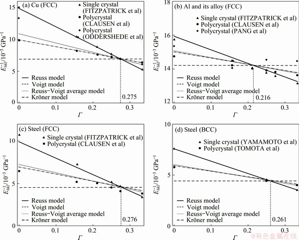
Fig. 2 Relationship between 1/Ehkl and �� from Reuss model, Voigt model, Reuss-Voigt average model, Kroner model [21-31] and measured results of Cu [21,24,25] (a), Al and its alloy [21,24,26] (b), austenitic steel (FCC) [21,24] (c) and ferritic steel (BCC) [30,31] (d)
Figure 2 summarizes the relationship between 1/Ehkl and �� from Reuss model, Voigt model, Reuss-Voigt average model, Kroner model [21-31] and the measured results of Cu [21,24,25], Al and its alloy [21,24,26], austenitic steel (FCC) [21,24] and ferritic steel (BCC) [30,31]. It is shown clearly that Reuss model indicates the most remarkable elastic anisotropy, and Voigt model gives isotropic results in above metals. Reuss model is also found to be on the verge of single crystals. Reuss-Voigt average model yields a result which is very close to the value of Kroner model. It is also well acceptable for good agreement with the measured results of polycrystalline aggregates. In addition, intersected points are observed from above plots which intersect approximate �� values of 0.275, 0.216, 0.276 and 0.261 for Cu, Al, FCC steel and BCC steel, respectively. A trait of common �� intersecting between 0.2 and 0.3 to other cubic materials was also observed but was not well explained [8,19-21].
To separate the simultaneous peak broadening of crystallite size (coherent diffracting domains) and orientation-dependent plastic lattice distortion, the pioneering Williamson-Hall (WH) method was proposed [32]:
 (5)
(5)
where ��K=��hklcos ��/��, ��hkl is the FWHM or integral breadth of peak broadening, �� is the diffraction angle, �� is the wavelength of diffraction source; ��=kc/d, kc is a constant and generally close to 0.9, d is crystallite size;  is the orientation- dependent plastic lattice strain; and K=2sin ��/��. The value of �� is generally independent of wavelength and angle of reflection [11]. The orientation- dependent values could be the results of the mean displacement from idea atomic position or the mean strain field of long-range dislocation. In other words, the variation of elastic constants in different crystallographic planes (Fig. 2) and/or the orientation-dependence of the distortion caused by the source of lattice strain leads to orientation- dependent values [11,33-35]. Inspired by the linear relationship between 1/Ehkl and �� in various models (Fig. 2), JIANG et al [8] developed the quasi elasto-plastic model based approach (i.e., direct fitting (DF) method) to correct strain anisotropy, as shown below:
 (6)
(6)
where ��hkl(=Ehkl/E*) is defined as the elastic modulus ratio, and ��Pla* is the lattice strain of reference reflection ((331) reflection in this work) which corresponds to above reference E*. And values could be estimated by  /��hkl. This approach was further confirmed to be effective and adaptive in practical application by linearization of the experimental dependences for line profile broadening in pure nickel under various cold-working strain paths [8].
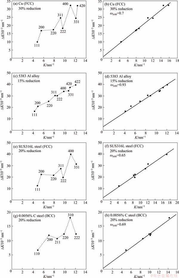
Fig. 3 Williamson-Hall (WH) plots [32] in deformed Cu (a), 5383 Al alloy (c), FCC steel (e) and BCC steel (g), and corresponding plots based on direct fitting (DF) method [8] in deformed Cu (b), 5383 Al alloy (d), FCC steel (f) and BCC steel (h)
In the present work, as shown in Fig. 3, the effective applications of the new DF method (Eq. (6)) are also demonstrated in cold worked Cu, 5383 Al alloy, SUS316L austenitic steel and 0.0056% C ferritic steel. In Figs. 3(a), (c), (e) and (g), the WH plots of ��K and K (Eq. (6)) show visible irregularities (non-linearity) due to strain anisotropy in various deformed metallic materials. The clearer anisotropies in Cu, SUS316L austenitic steel and 0.0056% C ferritic steel and Ni [8] than in 5383 Al alloy are indicated in the WH plots as well. It is well confirmed in elastic models and in situ neutron diffraction experiments [8,19,24,30] that the anisotropies of Cu, FCC steel, BCC steel and Ni are notable, while the anisotropy of Al alloy is negligible. The observed strain anisotropy magnitude of various lattice orientations also corresponds to that of elastic model (Fig. 2) [8]. For the most stiffness orientations of {111} or {222}, the values of ��K are smaller than average values. While for the less stiffness orientations of {200} or {400}, ��K values are the maximum. Hence, the stiffness of various lattice orientations strongly affects the observed strain anisotropy in LPA. By applying the new DF method (Eq. (6)), the strain anisotropies are well corrected to excellent linear plots (R2 >0.96), as indicated in Figs. 3(b), (d), (f) and (h). In the DF method, the anisotropy magnitude is indicated by ��h00 values. Small ��h00 values for the deformed Cu (0.7), FCC steel (0.65) and BCC steel (0.69) are observed. For 5383 Al alloy, larger ��h00 value (0.93) is presented, which is close to that of isotropic crystal (��h00=1). According to elastic models, Reuss model predicts the maximal anisotropy (Fig. 2), which corresponds to the minimal ��h00 values of 0.46, 0.46, 0.6 and 0.86 for Cu, FCC steel, BCC steel and Al and its alloy, respectively. For Voigt model, isotropic crystal is estimated which results in constant ��h00 value of 1 for all metals. For the more realistic model of polycrystalline aggregates, Kroner model estimates the ��h00 values of 0.67, 0.65, 0.72 and 0.93 for Cu, FCC steel, BCC steel and 5383Al alloy, respectively, which are very close to the obtained results from the present DF method (Figs. 3(b), (d), (f) and (h)). The results from DF method agree well with the anisotropy magnitude from elastic models.
3.2 Dislocation model based approach for strain anisotropy correction and dislocation density estimation
On the basis of dislocation theory, another effective solution to correct anisotropic strain broadening by utilizing the diffraction contrast factors of dislocations or dislocation-like lattice defects has been proposed and widely applied based on Wilkens model [4,6,7]:
 (7)
(7)
where  is the mean square strain, ��, b and C are the density, Burgers vector magnitude and contrast factors of dislocations, respectively, ��=L/Re, L is the Fourier variable, and Re is the effective outer cut-off radius of dislocations. The dislocation arrangement parameter (M) is also introduced to characterize the effective outer cut-off radius of dislocations with the relation of
  [6]. Then, the modified Williamson-Hall (mWH) method was developed by UNGAR and BORBELY [7]:
 (8)
(8)
where A and A�� are constants determined by the effective outer cut-off radius of dislocations, and parameter Q is related to the two-particle correlations in the dislocation ensemble. In addition, the Fourier transform (A(L)) of line profiles could also be corrected by introducing C, which was known as modified Warren-Averbach (mWA) method [7,36]:

 (9)
(9)
where As(L) is the size Fourier coefficient. The theoretical contrast factor (Chkl) is generally the product of two 4-rank tensors, namely the geometrical Gijmn and elastic Eijmn components [12].
 (10)
(10)
where Gijmn defines the orientation of g in the slip-system of the dislocation, and the elastic component Eijmn defines the distortion due to a dislocation. Due to the extreme complexity on the estimation of Chkl for individual dislocation in polycrystalline aggregates, the average diffraction contrast factors ( ) of particular orientation {hkl} are generally used in practical applications. The following linear dependence of with orientation parameter
  is essential in various methods, for instance, mWH/mWA method [6,7,37,38], whole powder pattern modelling (WPPM) method [10] and extended convolutional multiple whole profile (CMWP) method [39]:
 (11)
(11)
or
 (12)
(12)
where A1, B,  and q are the constants related to elastic constants and character of dislocations. Equation (12) is the particular form of Eq. (11) when
  (
( and q=-B/A1).
In practical implementations (mWH/mWA and CMWP methods), Eq. (12) is adopted more widely due to fewer input parameters [6,7,37-40]. Concretely, q value can be estimated from experimental results. Then, only value has to be determined theoretically as the most important input parameter in conventional approach, which can be calculated by numerical calculation [12], first-principle evaluation [40] and the convenient ANIZC program [41] based on given elastic constants. However, the calculated values of in previous works indicated strong dependence on elastic anisotropy magnitude (Ai=2c44/(c11-c12), c11, c12 and c44 are elastic constants) [12,40,41]. It is also well known that the elastic constants are remarkably different in particular metals and alloys because of the complex effects from chemical compositions, texture, dislocation characters, annealing treatments and testing methods [19,21,42]. For instance, DAYMOND et al [43] evaluated the elastic constants of FCC Ni by in situ neutron diffraction and gave larger Ai value (3.28) than that of single crystal Ni (Ai=2.53) from HEARMON [44]. MACHOVA and KADECKOVA [45] found that the Ai value (2.83) of 6.3% Si BCC steel was higher that of single crystal iron (Ai=2.42) [29]. Further, HARJO et al [46] determined the elastic constants of martensitic steel containing high dislocation density by in situ neutron diffraction. A remarkably smaller Ai value (1.59) was obtained. Therefore, notable deviations should exist between the input value and actual value of experimental specimens. The possible influences on quantitative dislocations density and characteristics evaluations resulted from such fluctuant values are essentially significant but less explored in conventional approaches [6,7,38-40].
To calculate the theoretical values by utilizing ANIZC program, the elastic constants cij or elastic stiffness constants Sij are essential input parameters [41]. Hence, the elastic constants of Ni [43,44,47-49], Cu [23,44,50-52], Al and its alloy [26,44,53-56], FCC steel [28,57-60] and BCC steel [29,45,46,61-63] are summarized in Table 1. Because of different elastic constants given in various works, wide ranges of anisotropy magnitude (Ai) are indicated in Table 1. Figure 4(a) shows the global effects from elastic constants and dislocation constituents (i.e., edge or screw) in Ni. When the same elastic constants [43,44] are adopted, the calculated values for pure edge dislocation are larger than those of pure screw dislocation. For particular dislocation constituent, the input elastic constants from different references [43,44] also influence values remarkably. Meanwhile, some common features are found: (1) values give the largest deviations; (2) The magnitudes of the slopes for linear plots of and �� are in proportion to Ai values; (3) Interesting intersections (Int), i.e.,  and ��Int, are observed for particular dislocation constituent (pure edge or pure screw), which are independent of input elastic constants. As shown in Table 1, the optimized intersections can also be obtained in other metals when dislocation constituent is fixed, though q values are found to change remarkably with variable Ai values. The corresponding �� values of the observed intersections fit well with those in elastic models (Fig. 2). It should be noted that only the values at existing hkl numbers can be calculated because �� is not a continuous function in actual situations. The observed ��Int values in Fig. 4 generally vary between (220) and (331) reflections. Figures 4(b-f) show the plots of theoretical values and �� in Ni [43,44,47-49], Cu [23,44,50-52], Al and its alloy [26,44,53-56], FCC steel [28,57-60] and BCC steel [29,45,46,61-63], which assumes equal probability of edge and screw dislocations. The optimized intersections are employed clearly in all metals. However, values, which are generally adopted as input parameters in conventional approaches [6,7,12,35,37,39,40], differ apparently due to the change of elastic constants from various references. In other words, is the most sensitive parameter to the input elastic constants.
Table 1 Results of elastic anisotropy and contrast factor in various materials
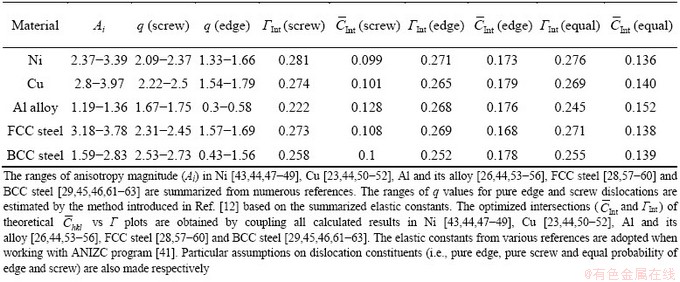
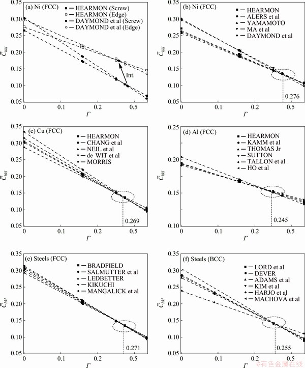
Fig. 4 Plots of theoretical values vs �� in Ni for pure edge or screw dislocations by utilizing different elastic constants of DAYMOND et al [43] and HEARMON [44] (a) and plots of values vs �� in Ni [43,44,47-49] (b), Cu [23,44,50-52] (c), Al and its alloy [26,44,53-56] (d), FCC steel [28,57-60] (e) and BCC steel [29,45,46,61-63] (f)
It is known that most elastic constants from above references are determined in well annealed specimens with little effect from texture and lattice distortions (e.g., dislocations). On the other hand, the experimental specimens always own high dislocation density and complex textures [6,7,12,35,39,40,46,64], which may result in a wider range of elastic constants (or anisotropy magnitude) [42-46]. Therefore, refined approaches are proposed currently based on conventional mWH/mWA and CMWP methods by adopting the above optimized intersections as input parameters. Unlike the fluctuant values in conventional approaches, the optimized intersections are found to be independent of the change of elastic constants (or anisotropy magnitude), which is the function of dislocations and textures (Table 1 and Fig. 4). In the implementation of refined approaches, q value is also estimated firstly based on experimental data. Then, the optimized intersections are used to calculate the adaptive  values:
 (13)
(13)
Further, (conventional methods) in Eq. (12) is replaced by (refined approaches) to correct the strain anisotropy in various line profile analysis methods [6,7,12,35,39,40]. Equal probability of edge and screw dislocations is assumed in the following analysis of this work, which is generally assumed in published works as well [6,7,18,39,46].
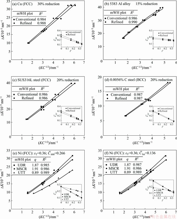
Fig. 5 Comparison of conventional and refined mWH plots in deformed samples of Cu (a), 5383 Al alloy (b), SUS316L austenitic steel (c), 0.0056% C ferritic steel (d) and conventional (e) and refined (f) mWH plots of cold-worked Ni at same true strain (��T) of 0.36 under various strain paths (UDR, MSCR and UTT) (Experimental plots of values vs �� are also given in lower right)
Figures 5(a-d) show the mWH plots of the deformed Cu, 5383 Al alloy, SUS316L austenitic steel and 0.0056% C ferritic steel by utilizing the conventional and refined approaches, respectively. It is observed that all plots show desired fitting relation with high correlation coefficients (R2). In classical WH plots of Figs. 3(a), (c), (e) and (g), much smaller R2 values are obtained which are generally in the range of 0.5-0.8. Slight differences are indicated in the conventional and refined mWH plots due to different values, as presented in the lower right of Figs. 5(a-d). In Fig. 5(e), the conventional mWH plots of cold-worked Ni at the same true strain (��T) of 0.36 under various strain paths (UDR, MSCR and UTT) are presented. Clear deviations are revealed in the plot of UTT specimen when compared with that of UDR and MSCR samples. But the refined mWH plots in Fig. 5(f) are approximately identical. Looking into the experimental values in the lower right of Figs. 5(e, f), the implemented modes for the rectification of strain anisotropy are different in conventional and refined approaches. The conventional approaches fix value while the refined approaches fix value. The experimental value at ��Int of 0.276 in UTT specimen differs remarkably in the conventional approaches (Fig. 5(e)). In the refined approaches (Fig. 5(f)), values vary clearly because of the change of q values. It is clear that the screening in refined approaches fits the plots of theoretical and �� (Fig. 4(b)) better. It seems that the input or values in the conventional and refined mWH approaches do not affect the effective correction of strain anisotropy. The key factor which influences the effectiveness of strain anisotropy correction is the linear relationship of and ��. As exhibited in previous quasi elasto-plastic model based DF method, the linear relationship between 1/Ehkl and �� is also the essential origin of strain anisotropy. Hence, by applying the linear relationship between 1/��hkl and ��, DF method can adaptively correct the lattice strain anisotropy in cold-worked specimens [8]. In subsequent mWA method (Eq. (9)), as shown in Fig. 6, the obtained values from mWH plot are directly adopted to correct the anisotropy in Fourier analysis for the estimation of dislocation density [7,12,37]. It is also indicated that the strain anisotropy in Fourier transform analysis of mWA plots is well corrected in both conventional and refined approaches. However, because of different input values, the detailed plots are different and various dislocation densities are estimated, especially in UTT sample (Figs. 6(e, f)).
Figure 7 shows typical XRD patterns of cold-worked Ni at the same true strain (��T) of 0.36 under various strain paths (i.e., UDR, MSCR and UTT). The experimental (Exp.) patterns are compared with the calculated (Cal.) results by conventional CMWP method with fixed input value of 0.266 (Table 1) in Fig. 7(a) [12,44]. Good agreements are observed with slight differences (Dif.). Various q values are resulted from the change of strain paths owing to different microstructural characteristics, as shown in Fig. 8. The micro textures in UDR and UTT specimens (Fig. 8(a)) present primary components of Cu{112}(111), Bs{110}(112) and S{123}(634). Very strong preferred orientations or textures are observed in UTT specimen. In MSCR specimen, weaker texture by clustering orientations into four lobes around the center near Bs orientation is characterized. At the same time, Cu orientation is almost absent. In Fig. 8(b), UDR and UTT specimens indicate dislocations which tangle along the apparent cell boundaries. Especially for UTT sample, the tangled dislocations lead to much stronger interactions and thinner cell walls. While MSCR sample presents more uniform dislocation distribution than UDR and UTT specimens. When carrying out the refined CMWP method, similar diffraction patterns and matches are observed in Fig. 7(b) because the experimental and physically calculated patterns are matched by the Marquard- Levenberg non-linear least squares function in CMWP program [4,39]. By comparing the estimated dislocation density results under the same cold-worked condition from conventional (Fig. 7(a)) and refined approaches (Fig. 7(b)), certain deviations are found. The magnitudes of dislocation density deviations depend on experimental q values, which leads to adaptive input values (Eq. (13)) in the refined approach.
Fig. 6 Comparison of conventional and refined mWA plots of cold-worked Ni at same true strain (��T) of 0.36 under various strain paths
The magnitudes of deviation for the estimated dislocation density in conventional and refined mWH/mWA methods also depend on the experimental q values (Fig. 5(e, f)). Though the absolute q values are different in CMWP and mWH/mWA methods, the tendencies are identical, i.e., qMSCR>qUDR>qUTT. The effects of strain paths on q values are due to various microstructures as observed in Fig. 8. Furthermore, the estimated dislocation density in MSCR specimen is much lower than that in UDR and UTT specimens. The reason is that both CMWP and mWH/mWA methods give 2-4 times larger M values in MSCR specimen than that in UDR and UTT specimens. For instance, M values are 1.32 (MSCR), 0.43 (UDR) and 0.37 (UTT) by utilizing conventional mWA method. The dislocation microstructure under transmission electron microscopy (TEM) in Fig. 8 confirms that MSCR leads to uniform dislocation distribution (corresponding to larger M value) while UDR and UTT prefer heterogeneous microstructures.
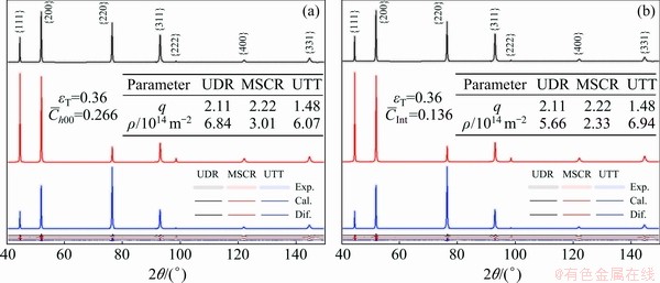
Fig. 7 Typical experimental and calculated XRD patterns of cold-worked Ni at same true strain (��T) of 0.36 under various strain paths (UDR, MSCR and UTT) by conventional (a) and refined (b) CMWP methods (The differences are also presented)
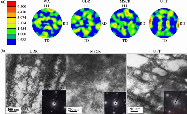
Fig. 8 Micro textures of Ni under WA, UDR (��T=0.36), MSCR (��T=0.36), and UTT (��T=0.36) states obtained by EBSD examination (a) and TEM bright field (BF) images showing dislocation characters (g=[111]) of deformed Ni under various strain paths (UDR, MSCR and UTT) (b) (The selected area electron diffraction patterns are also given in lower right)
To systematically explore the magnitude of deviations on the estimated ��, Re, M and Lc (crystallite size) values in the refined and conventional approaches [4,6,7,12,46], Fig. 9 shows the plots of the ratios (��(��), ��(Re), ��(M), ��(Lc), ��(��)=��refined/��conventional, ��(Re)=Re refined/Re conventional, ��(M)=Mrefined/Mconventional, ��(Lc)=Lc refined/Lc conventional) of obtained ��, Re, M and Lc values and the ratio  of input / values in all examined specimens. It is found that the estimated �� and M values strongly depend on input / values in both CMWP and mWH/mWA methods. The maximum deviations on �� values are approximately 41% in CMWP method and 49% in mWH/mWA method. For M values, the maximum deviations are about 23% in CMWP method and 22% in mWH/mWA method. The actual deviations are the functions of experimental q or values (Eq. (13)). Further enlarging the range of q values may lead to larger deviations. It is also found that the estimated Re and Lc values almost have no correlations with the input / values. Therefore, the present refined approaches based on the optimized intersections are intensively recommended to obtain more reliable results when applying dislocation model based LPA in cubic metals. At the same time, the effects of edge/ screw dislocation constituent on the optimized intersections are also important. In previous efforts [4,6,7,12,39,40], elastic constants (or anisotropy) contributions, which were found to be crucial in Table 1, were neglected to estimate edge/screw dislocation fraction. Therefore, further efforts are needed to separate the coupled contributions of dislocation constituent and elastic constants (or anisotropy) on q values for determining actual edge/screw dislocation portion. Then, more precise intersections can be adaptively determined without primary assumptions.
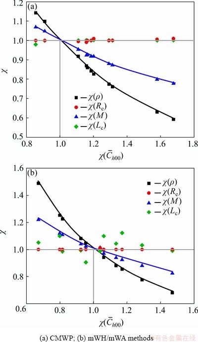
Fig. 9 Plots of ratios (��(��), ��(Re), ��(M), ��(Lc)) of obtained ��, Re, M and Lc values and ratio  of input
  / values in refined and conventional approaches
4 Conclusions
(1) Various levels of anisotropy were indicated in different elastic models of cubic metals (e.g., Cu, Al, FCC steel and BCC steel) and stable intersections were observed from the plots of 1/Ehkl vs ��. The quasi elasto-plastic model based DF method was found to effectively correct the remarkable strain anisotropy in cold-worked Cu, 5383 Al alloy, SUS316L austenitic steel and 0.0056% C ferritic steel. The anisotropic results from DF method also agreed well with the anisotropy magnitude from elastic models.
(2) By employing the summarized elastic constants as the input parameters, the optimized intersections were found by analyzing the plots of calculated values vs �� in various cubic metals (i.e., Ni, Cu, Al and its alloy, FCC steel and BCC steel). The plots of values vs �� were close to the ranges of anisotropy magnitude (Ai) and the observed �� values of the intersections (��Int) were approximate to those in elastic models.
(3) Based on the above interesting intersections, the refined dislocation model based LPA approaches were developed by adopting the optimized intersections as input values other than the values in conventional approaches. By implementing the CMWP and mWH/mWA methods in cold-worked Ni specimens under various strain paths, the refined approaches were found to be more reasonable and reliable. The estimated �� and M values strongly depended on input / values in refined or conventional approaches. The maximum deviations of the estimated �� and M values in this work were approximately 49% and 23%, respectively. The estimated Re and Lc values were almost identical within experimental errors.
References
[1] Taylor G I. The mechanism of plastic deformation of crystals (Part I) [J]. Proceedings of the Royal Society of London: Series A, 1934, 145: 362-387.
[2] MA Yun-long, LI Jin-feng, SANG Feng-jian, LI Hong-ying, ZHENG Zi-qiao, HUANG Cheng. Grain structure and tensile property of Al-Li alloy sheet caused by different cold rolling reduction [J]. Transactions of Nonferrous Metals Society of China, 2019, 29(8): 1569-1582.
[3] Devincre B, Hoc T, Kubin L. Dislocation mean free paths and strain hardening of crystals [J]. Science, 2008, 320(5884): 1745-1748.
[4] UngAr T, Stoica A D, Tichy G, Wang X L. Orientation-dependent evolution of the dislocation density in grain populations with different crystallographic orientations relative to the tensile axis in a polycrystalline aggregate of stainless steel [J]. Acta Materialia, 2014, 66: 251-261.
[5] Mughrabi H. The ��-factor in the Taylor flow-stress law in monotonic, cyclic and quasi-stationary deformations: Dependence on slip mode, dislocation arrangement and density [J]. Current Opinion in Solid State & Materials Science, 2016, 20(6): 411-420.
[6] Wilkens M. The determination of density and distribution of dislocations in deformed single crystals from broadened X-ray diffraction profiles [J]. Physics Status Solidi (a), 1970, 2(2): 359-370.
[7] UngAr T, BorbEly A. The effect of dislocation contrast on X-ray line broadening: A new approach to line profile analysis [J]. Applied Physics Letters, 1996, 69(21): 3173-3175.
[8] Jiang F, Masumura T, Hirata K, Tsuchiyama T, Takaki S. A new diffraction line profile breadth analysis approach for evaluating plastic lattice strain anisotropy in cold-worked nickel under various strain paths [J]. International Journal of Plasticity, 2019, 112: 89-107.
[9] Simm T H. Peak broadening anisotropy and the contrast factor in metal alloys [J]. Crystals, 2018, 8(5): 212.
[10] JIANG J, BRITTON T B, WILKINSON A J. The orientation and strain dependence of dislocation structure evolution in monotonically deformed polycrystalline copper [J]. International Journal of Plasticity, 2015, 69: 102-117.
[11] Stokes A R, Wilson A C J. The diffraction of X-ray by distorted crystal aggregates��I [J]. Proceedings of the Physical Society, 1944, 56: 174-181.
[12] UngAr T, Dragomir I, Revesz A, BorbEly A. The contrast factors of dislocations in cubic crystals: The dislocation model of strain anisotropy in practice [J]. Journal of Applied Crystallography, 1999, 32(5): 992-1002.
[13] Masumura T, Takaki S, Jiang F, Tsuchiyama T. Discussion about procedure for determining parameter �� in modified Williamson-Hall method [J]. Tetsu-to-HaganE, 2018, 104(11): 717-719.
[14] Takaki S, Masumura T, Jiang F, Tsuchiyama T. Effect of instrumental correction on X-ray line profile analysis in cold rolled ferritic steel [J]. ISIJ International, 2018, 58(6): 1181-1183.
[15] MA Yun-long, LI Jin-feng, ZHANG Run-zhe, TANG Jian-guo, HUANG Cheng, LI Hong-ying, ZHENG Zi-qiao. Strength and structure variation of 2195 Al-Li alloy caused by different deformation processes of hot extrusion and cold-rolling [J]. Transactions of Nonferrous Metals Society of China, 2020, 30: 835-849.
[16] ZHANG Da-wei, ZHAO Sheng-dun, YANG He. Analysis of deformation characteristic in multi-way loading forming process of aluminum alloy cross valve based on finite element model [J]. Transactions of Nonferrous Metals Society of China, 2014, 24: 199-207.
[17] Jiang F, Hirata K, Masumura T, Tsuchiyama T, Takaki S. Effect of the surface layer strained by mechanical grinding on X-ray diffraction analysis [J]. ISIJ International, 2018, 58(2): 376-378.
[18] ABOUHILOU F, KHEREDDINE A, ALILI B, BRADAI D. X-ray peak profile analysis of dislocation type, density and crystallite size distribution in cold deformed Pb-Ca-Sn alloys [J]. Transactions of Nonferrous Metals Society of China, 2012, 22: 604-607.
[19] Hutchings M T, Withers P J, Holden T M, Lorentzen T. Introduction to the characterization of residual stress by neutron diffraction [M]. Florida: CRC Press, 2005.
[20] Murray C E. Equivalence of Kroner and weighted Voigt-Reuss models for X-ray stress determination [J]. Journal of Applied Physics, 2013, 113: 1-12.
[21] Fitzpatrick M E, Lodini A. Analysis of residual stress by diffraction using neutron and synchrotron radiation [M]. Florida: CRC Press, 2003.
[22] Hill R. The elastic behaviour of a crystalline aggregate [J]. Proceedings of the Physical Society, 1952, 65: 349-354.
[23] Chang Y A, Himmel L. Temperature dependence of the elastic constants of Cu, Ag, and Au above room temperature [J]. Journal of Applied Physics, 1966, 37(9): 3567-3572.
[24] Clausen B, Lorentzen T, Leffers T. Self-consistent modelling of the plastic deformation of fcc polycrystals and its implications for diffraction measurements of internal stresses [J]. Acta Materialia, 1998, 46(9): 3087-3098.
[25] Oddershede J, Schmidt S, Poulsen H F, Margulies L, Wright J, Moscicki M, Reimers W, Winther G. Grain-resolved elastic strains in deformed copper measured by three-dimensional X-ray diffraction [J]. Materials Characterization, 2011, 62(7): 651-660.
[26] Kamm G N, Alers G A. Low-temperature elastic moduli of aluminum [J]. Journal of Applied Physics, 1964, 35(2): 327-330.
[27] Pang J W L, Holden T M, Mason T E. In situ generation of intergranular strains in an Al7050 alloy [J]. Acta Materialia, 1998, 46(5): 1503-1518.
[28] Mangalick M C, Fiore N F. Orientation dependence of dislocation damping and elastic constants in Fe-18Cr-Ni single crystals [J]. Transactions of the American Institute of Mining, Metallurgical and Petroleum Engineers, 1968, 242: 2363-2364.
[29] Lord A E Jr, Beshers D N. Elastic stiffness coefficients of iron from 77 to 673 K [J]. Journal of Applied Physics, 1965, 36: 1620-1623.
[30] Tomota Y, Harjo S. Deformation behavior of ferrous materials studied by using neutron diffraction [J]. Journal of the Japan Society for Technology of Plasticity, 2013, 54: 891-895.
[31] Yamamoto S, Asabe K, Nishiguchi M, Maehara Y. Recrystallization texture and Young��s modulus of ceramic particle dispersed ferrite steel bars [J]. Tetsu-to-HaganE, 1996, 82(9): 771-776.
[32] Williamson G K, Hall W H. X-ray line broadening from filed aluminium and wolfram [J]. Acta Metallurgica, 1953, 1(1): 22-31.
[33] Stephens P W. Phenomenological model of anisotropic peak broadening in powder diffraction [J]. Journal of Applied Crystallography, 1999, 32(2): 281-289.
[34] Popa N C. The (hkl) dependence of diffraction-line broadening caused by strain and size for all Laue groups in Rietveld refinement [J]. Journal of Applied Crystallography, 1998, 31(2): 176-180.
[35] Dinnebier R E, Billinge S J L. Powder diffraction: Theory and practice [M]. Cambridge: Royal Society of Chemistry, 2008.
[36] Warren B E, Averbach B L. The effect of cold-work distortion on X-ray patterns [J]. Journal of Applied Physics, 1950, 21: 595-599.
[37] KHEREDDINE A, HADJ LARBI F, DJEBALA L, AZZEDDINE H, ALILI B, BRADAI D. X-ray diffraction analysis of cold-worked Cu-Ni-Si and Cu-Ni-Si-Cr alloys by Rietveld method [J]. Transactions of Nonferrous Metals Society of China, 2011, 21: 482-487.
[38] Groma I, UngAr T, Wilkens M. Asymmetric X-ray line broadening of plastically deformed crystals. I: Theory [J]. Journal of Applied Crystallography, 1988, 21(1): 47-54.
[39] RibArik G, Gubicza J, UngAr T. Correlation between strength and microstructure of ball-milled Al-Mg alloys determined by X-ray diffraction [J]. Materials Science and Engineering A, 2004, 387: 343-347.
[40] Mittemeijer E J, Scardi P. Diffraction analysis of the microstructure of materials [M]. Heidelberg: Springer-Verlag, 2013.
[41] BorbEly A, Dragomir-Cernatescu J, RibArik G, UngAr T. Computer program ANIZC for the calculation of diffraction contrast factors of dislocations in elastically anisotropic cubic, hexagonal and trigonal crystals [J]. Journal of Applied Crystallography, 2003, 36(1): 160-162.
[42] Kocks U F, TomE C N, Wenk H R, Texture and anisotropy: preferred orientations in polycrystals and their effect on materials properties [M]. Cambridge: Cambridge University Press, 2000.
[43] Daymond M R, Preuss M, Clausen B. Evidence of variation in slip mode in a polycrystalline nickel-base superalloy with change in temperature from neutron diffraction strain measurements [J]. Acta Materialia, 2007, 55(9): 3089-3102.
[44] Hearmon R F S. The elastic constants of non- piezoelectric crystals [J]. Landolt-Bornstein, 1966, 1: 1-39.
[45] MachovA A, KadeCkovA S. Elastic constants of iron-silicon alloy single crystals [J]. Czechoslovak Journal of Physics, 1977, 27(5): 555-563.
[46] Harjo S, Kawasaki T, Tomota Y, Gong W, Aizawa K, Tichy G, Shi Z, UngAr T. Work hardening, dislocation structure, and load partitioning in lath martensite determined by in situ neutron diffraction line profile analysis [J]. Metallurgical and Materials Transactions A, 2017, 48(9): 4080-4092.
[47] Alers G A, Neighbours J R, Sato H. Temperature dependent magnetic contributions to the high field elastic constants of nickel and an Fe-Ni alloy [J]. Journal of Physics and Chemistry of Solids, 1960, 13(1-2): 40-55.
[48] Yamamoto M. On elastic constants of nickel crystals [J]. Physical Review, 1950, 77(4): 308-320.
[49] Ma S, Rangaswamy P, Majumdar B S. Microstress evolution during in situ loading of a superalloy containing high volume fraction of �á� phase [J]. Scripta Materialia, 2003, 48(5): 525-530.
[50] Neil C J, Wollmershauser J A, Clausen B, TomE C N, Agnew S R. Modeling lattice strain evolution at finite strains and experimental verification for copper and stainless steel using in situ neutron diffraction [J]. International Journal of Plasticity, 2010, 26: 1772-1791.
[51] de Wit R. Diffraction elastic constants of a cubic polycrystal [J]. Journal of Applied Crystallography, 1997, 30: 510-511.
[52] Morris P R. Elastic constants of polycrystals [J]. International Journal of Engineering Science, 1970, 8: 49-61.
[53] Thomas J F Jr. Third-order elastic constants of aluminum [J]. Physical Review, 1968, 175: 955-962.
[54] Sutton P M. The variation of the elastic constants of crystalline aluminum with temperature between 63 K and 773 K [J]. Physical Review, 1953, 91: 816-821.
[55] Tallon J L, Wolfenden A. Temperature dependence of the elastic constants of aluminum [J]. Journal of Physics and Chemistry of Solids, 1979, 40: 831-837.
[56] Ho P S, Ruoff A L. Pressure dependence of the elastic constants for aluminum from 77 to 300 K [J]. Journal of Applied Physics, 1969, 40: 3151-3156.
[57] Bradfield G. Comparison of elastic anisotropy of 2 austenitic steels [J]. Journal of the Iron and steel Institute, 1964, 202: 616-621.
[58] Salmutter K, Stangler F. Elasticity of plasticity of an austenitic chromium-nickel steel [J]. Zeitschrift f��r Metallkunde, 1960, 51: 1-4.
[59] Ledbetter H M. Predicted monocrystal elastic constants of 304-type stainless steel [J]. Physica B+C, 1985, 128: 1-4.
[60] Kikuchi M. Elastic anisotropy and its temperature dependence of single crystal and polycrystal of 18-12 type stainless steel [J]. Transactions of the Japan Institute of Metals, 1971, 12: 417-421.
[61] Dever D J. Temperature dependence of the elastic constants in ��-iron single crystals: Relationship to spin order and diffusion anomalies [J]. Journal of Applied Physics, 972, 43(8): 3293-2364.
[62] Adams J J, Agosta D S, Leisure R G, Ledbetter H. Elastic constants of monocrystal iron from 3 to 500 K [J]. Journal of Applied Crystallography, 2006, 100: 113530-1-7.
[63] Kim S A, Johnson W L. Elastic constants and internal friction of martensitic steel, ferritic-pearlitic steel, and ��-iron [J]. Materials Science and Engineering A, 2007, 452: 633-639.
[64] DU Chao-liang, WANG Yi-shou, GAO Dong-yue, LIU Ke-hai, QING Xin-lin. In-situ quantitative monitoring of fatigue crack using fastest time of flight diffraction method [J]. Transactions of Nonferrous Metals Society of China, 2012, 22: 2679-2684.
�������������������η�������������Ӧ���������ģ��
�� ��1��������1,2���� ��1��������1��������1���� ��1���� ��1
1. ���ϴ�ѧ ���Ͽ�ѧ�빤��ѧԺ����ɳ 410082��
2. Research Center for Steel, Kyushu University, 744 Motooka Nishi-ku, Fukuoka 819-0395, Japan
ժ Ҫ��Ϊ��̽������Ӧ��������Եı���ԭ��ϵͳ�������ò�ͬ����ģ�ͼ����������������(ͭ��5383���Ͻ���������������ֺ����������������)�ĸ������Գ̶ȡ�ģ�ͺ�ʵ��������ʾ����ģ���ĵ���(1/Ehkl)��ȡ����� (��)֮��Ĺ�ϵ���߾����ȶ��Ľ���㣬����һ����֤����������ģ�͵����ο��������������������Ʒ������Ӧ��������Ե���Ч�ԡ����ͬʱ��ͨ���Ի���λ��ģ�͵����η�������������Ҫ��ƽ������Ա����Ӳ���(Chkl)�������֣�����ֵ�뵯�Գ���������أ����۲쵽Chkl�릣���ߴ�����Ȥ�Ľ���㡣��ˣ��ڴ�ͳ�������η��������У��������Ch00ֵ��������Գ����IJ�ͬ�����ֽϴ�������Ӱ�����շ����������Ӧ�أ��������һ�ָ��������η����������������Ż����ȶ��������Ϊ��ʼ����ֵ����ø��ɿ��Եķ��������
�ؼ��ʣ��������ϣ����η�����Ӧ��������ԣ�λ��
(Edited by Wei-ping CHEN)
Foundation item: Project (51904099) supported by the National Natural Science Foundation of China; Project (531118010353) supported by the Fundamental Research Funds for the Central Universities, China
Corresponding author: Fu-lin JIANG; Tel: +86-731-88664086; Fax: +86-731-88821483;
E-mail: jfling2820@163.com; fulin.jiang.88@hnu.edu.cn
DOI: 10.1016/S1003-6326(20)65363-8
Abstract: The present work examined the anisotropy magnitudes obtained from different elastic models of cubic metals (Cu, 5383 Al alloy, FCC austenite steel and BCC steel) to explore the origin of strain anisotropy. The results showed that stable intersections were observed from the modeled and experimental plots of the reciprocal elastic modulus (1/Ehkl) and orientation parameter (��). The effectiveness of quasi elasto-plastic model based method in correcting strain anisotropy was further verified in cold-worked specimens. For the important input parameters in dislocation model based diffraction line profile analysis methods, the average diffraction contrast factors of dislocations were observed to depend on elastic constants. Interesting intersections were found from linear dependence of on ��. The conventional input values indicated distinct dependencies on given elastic constants in diffraction line profile analysis. Accordingly, a refined approach was proposed by adopting the optimized intersections as input values, by which more reliable results could be obtained in practical applications.
[48] Yamamoto M. On elastic constants of nickel crystals [J]. Physical Review, 1950, 77(4): 308-320.
" target="blank">[64] DU Chao-liang, WANG Yi-shou, GAO Dong-yue, LIU Ke-hai, QING Xin-lin. In-situ quantitative monitoring of fatigue crack using fastest time of flight diffraction method [J]. Transactions of Nonferrous Metals Society of China, 2012, 22: 2679-2684.
