
Trans. Nonferrous Met. Soc. China 27(2017) 2043-2054
Residual stress distribution in different depths of TiNi/Ti2Ni-based laser clad coating prepared at different environmental temperatures
Yang-feng TAO, Jun LI, Ying-hao  , Lie-feng HU
School of Materials Engineering, Shanghai University of Engineering Science, Shanghai 201620, China
Received 5 June 2016; accepted 9 October 2016
Abstract:
This study aimed to effectively reduce the cracking susceptibility of the laser clad coating by enhancing the environmental temperature during laser cladding, and reveal the residual stress distribution in different depths of the coating. The TiNi/Ti2Ni-based coatings were prepared on Ti6Al4V by laser cladding at different environmental temperatures of 25, 400, 600 and 800 ��C. The changes in residual stress along the depth of the coatings were investigated in detail by the nanoindentation method. Results showed that the average residual stress of 2.90 GPa in the coating prepared at 25 ��C was largest. With the increase in environmental temperature, the average residual stress was reduced to 1.34 GPa (400 ��C), 0.70 GPa (600 ��C) and 0 GPa (800 ��C). For all the coatings, the residual stress was increased with increasing the distance from the coating surface. Enhancing the environmental temperature can effectively reduce the cracking susceptibility of the coatings.
Key words:
laser cladding; coating; microstructure; environmental temperature; cracking susceptibility; residual stress; nanoindentation;
1 Introduction
Titanium alloys are widely used as high- performance materials in the aerospace, petro-chemical, medical, and aircraft industries due to their low density, high specific strength, exceptional corrosion resistance and high-temperature mechanical properties. However, the application of these alloys in other industrial fields is restricted due to their poor tribological properties and low hardness [1]. Thus, some surface-modification techniques are used to improve the surface structures and properties of titanium alloys by changing their surface compositions [2,3]. Among these techniques, laser cladding is regarded as an excellent technology to fully optimize the properties of mechanical components, such as limited heat-affected zone, minimal stress deformation and good metallurgical bonding between the coating and the substrate [4,5].
Although laser cladding has many advantages, high residual stress usually generates in the coating because of its rapid heating and cooling characteristics. Consequently, the coating fabricated by laser cladding possesses very high cracking susceptibility, which is a critical shortcoming that vastly limits the industrial application of this technique. Thus, it is very necessary to reduce the cracking susceptibility of the laser clad coating. Several methods have been used to reduce the cracking susceptibility, including designing the cladding-material compositions, optimizing the processing parameters and preheating the substrate. WANG et al [6] prepared the coatings on 45# steel by laser cladding the NiCrBSiC alloy powders doped with V2O5. They found that the number of cracks was significantly decreased with the increase in content of V2O5. Furthermore, no cracks generated in the coatings when the content of V2O5 was increased to 4%-5% (mass fraction). WENG et al [7] fabricated the coatings on Ti6Al4V substrates by laser cladding the mixtures of Co42 self-fluxing alloy, TiN and Y2O3. The coating with 1.0% Y2O3 (mass fraction) addition showed good metallurgical bonding with the substrate and was free of pores and cracks.
RIQUELME et al [8] produced the SiC-reinforced Al matrix coatings on ZE41 magnesium alloy using a high-power diode laser (HPLD). The results showed that the optimal parameters for laser cladding were 650 W of laser output power and 17 mm/s of laser scanning speed, in which the coating with few interface pores and cracks had excellent microstructure and mechanical properties. ZHOU et al [9] prepared the Ni-based composite coatings on A3 mild steel at different processing parameters. The results indicated that cracking susceptibility was increased with increasing the laser output power and laser scanning speed. There were few cracks in the coating when the laser scanning speed was 480 mm/min and the laser output power was 2.5 kW.
The two methods mentioned above can effectively decrease the cracking susceptibility of the laser clad coating. However, the selected compositions or parameters may be only suitable to the specific combination of the coating and the substrate, and may have to be adjusted when the coating or the substrate changes. Compared with the above two methods, preheating the substrate is more universal as it can markedly reduce the residual stress in the coating due to the reduction in temperature change between the coating and the substrate. As a result, the cracking susceptibility of the coating is reduced or even eliminated. FALLAH et al [10] prevented the crack initiation in the coating by preheating the substrate prior to laser cladding of the hardfacing alloy stellite 1 on AISI-SAE 4340 steel. LESTAN et al [11] investigated the deposition of the Metco 15 E powders on cast iron by the laser-engineered net shaping (LENSTM) technology. The number of cracks in the coatings was significantly decreased by preheating the substrates.
The cracking susceptibility of the coating is usually evaluated by crack number [12], fracture toughness [13] and residual stress [14] in the coating. The number of cracks cannot be used to evaluate the crack-free coating and to quantitatively evaluate the cracking susceptibility of the coating. Fracture toughness of the coating is usually measured by the Vickers indentation method. This method had been used to evaluate fracture toughness of the laser clad coating in previous studies [15,16]. Fracture toughness of the coating can be calculated with the following equation [16]:
 (1)
(1)
where KIC is fracture toughness (MPa��m1/2), P is the applied load (N), a is the half-length of the diagonal line in an indentation (m), and c is the half-length of cracks (m).
However, the method presents the very low precision because of the two reasons. On one hand, based on different models, different equations are derived and applied to calculating fracture toughness, which leads to different calculations. On the other hand, it is very difficult to precisely measure the crack length due to the irregular and asymmetric cracks produced in the four corners of the indentation. The cracking susceptibility of the coating is increased with the increase in residual stress of the coating. Thus, it can be evaluated by the residual stress in the coating. The residual stress can be calculated by several methods such as X-ray diffraction, hole-drilling and nanoindentation method. However, the X-ray diffraction method has a very strict requirement for the surface of the coating and is inapplicable to the material composed of complicated phases [17]. The residual stress measured by the hole-drilling method may be affected by the equipment operators. Other than that, it is difficult to punch onto the materials with high hardness. Due to its depth-sensing capability, the nanoindentation method as an effective tool can be used to determine the residual stress in the coating. The nanoindentation method had been adopted to accurately measure the residual stress in the coating by DEAN et al [18], ZHU et al [19], WANG et al [20] and KHAN et al [21].
In this work, the TiNi/Ti2Ni-based coatings were prepared on Ti6Al4V alloy by laser cladding at different environmental temperatures. The residual stress in the zones with different depths of the coatings was calculated by the nanoindentation method. Moreover, the effects of the environmental temperature on the cracking susceptibility of the coatings were investigated in detail.
2 Experimental
2.1 Pre-placed layer preparation
Ti6Al4V alloys (composition in mass fraction, 6.5% Al, 4.26% V, 0.1% C and balanced Ti) were used as the substrate and cut into the samples with dimensions of 30 mm �� 20 mm �� 10 mm. They were ground with 150-grit SiC abrasive papers and ultrasonically cleaned in ethanol for 15 min. The cladding materials were composed of 10% B4C and 90% F102 Ni-based alloy with the compositions (mass fraction) of 75% Ni, 1% C, 16% Cr, 3.5% B, and 4.5% Si. The binder (4% polyvinyl alcohol) was placed on the surface of the substrate with a brush, and then it was placed into a model (30.2 mm in length, 20.2 mm in width, and 10.8 mm in height). The mixed powder was filled into the empty space with 0.8 mm in height above the surface of the substrate in the model. The powder was compacted with a tablet machine at 30 MPa for 3 min to obtain the pre-placed layer with about 0.8 mm in thickness.
2.2 Laser cladding
Before laser cladding, the samples were preheated to 400, 600 and 800 ��C in the resistance furnace. Laser cladding was performed using a YLS-5000 fiber laser processing system with the following parameters: power 3 kW, spot diameter 6 mm, and scanning speed 10 mm/s. The prepared coatings were named as coatings II, III and IV, respectively. The other coating was prepared on the sample without preheating (25 ��C) and named as coating I.
2.3 Microstructural characterization
Phase constituents of the coatings were analyzed using a PANalytical X�� Pert Pro X-ray diffractometer (XRD) with Cu K�� radiation (��=0.1540560 nm). A scanning range of 20��-90�� and a scanning speed of 0.013 (��)/s were adopted. The surfaces of the coatings were ground with 150-grit SiC abrasive papers prior to the testing. The metallographic specimens were prepared along the cross sections of the samples and etched with a mixed solution consisting of 4 mL of H2O, 6 mL of HNO3 and 6 drops of HF for 25 s. Microstructural characterization was examined using an S-3400 scanning electron microscope (SEM) and a GENESIS EDAX energy dispersive spectrometer (EDS).
2.4 Nanoindentation tests
Nanoindentation tests were performed using a TriboIndenterTM (Hysitron Corporation, USA) with a diamond Berkovich indenter. The indenter was also used as an AFM tip to observe the indentation surface morphology after the indentation tests. The surface roughness of the coating significantly affects the measurement precision of mechanical properties (such as hardness and elastic modulus). Therefore, prior to the tests, the surfaces of the coatings were processed to reduce the surface roughness. The surfaces of the coatings were ground successively with 600-, 1000-, and 1200-grit SiC abrasive papers in an M-2 pre-grinder and then polished using the diamond spray polishing agent in a P-2 metallographic polishing machine. After that, the polished surfaces were observed at 400 times magnification using a VHX-600K optical microscope. The surfaces without visible scratches were used for nanoindentation tests. AFM results indicated that the roughness (Ra) of the sample surfaces was 6 nm, which met the requirements of nanoindentation tests. The allowable maximum peak load in the TriboIndenterTM (Hysitron Corporation, USA) is 10 mN. In order to reduce the measurement error of hardness caused by the size effect as far as possible, the peak load of 10 mN was selected to prepare the indentations with a depth of 100-200 nm in the tests. The loading and unloading time were all set at 5 s, and the peak load was maintained for 5 s. In order to avoid the effect of the size effect on the measure precision of hardness, the indentation depth should be not less than one-tenth of the sample thickness. The thickness of the coatings is about 2 mm. As far as the coatings as a whole are concerned, the indentation depth (100-200 nm) does not meet the one-tenth criterion. However, the study focused on the hardness distribution along the depth direction of the coatings, further revealed the residual stress distribution in different depths of the coatings. Therefore, some sublayers (with a thickness of 1-2 mm) located at different depths of the coatings were selected as the research objects. From the perspective, the one-tenth criterion can be satisfied for every sublayer in the coatings. As shown in Fig. 1, the first group of nanoindentations were prepared at sublayer 1 with 0.1 mm distance from the coating surface. The next group of indentations were prepared at different sublayers with the same distance interval (0.4 mm). Every group included five indentations and the distance between the adjacent indentations was fixed at about 20 mm. Due to the change in thickness of the coatings, three and five sublayers were selected for the coatings prepared at 25 ��C and high temperatures (400, 600 and 800 ��C), respectively.
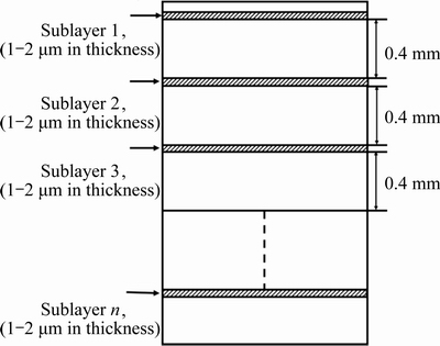
Fig. 1 Schematic diagram of nanoindentation tests
The indentations with a depth of 100-200 nm were also prepared in the thick coatings to estimate the residual stress by some researchers. ZHU et al [19] calculated the residual stress in the thick coating by preparing the indentations with a depth of 100-200 nm. LI [22] also carried out the similar research and the results showed that the residual stress measured by preparing the indentations with a depth of about 200 nm was very close to that calculated by the X-ray diffraction method.
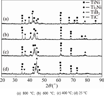
Fig. 2 XRD patterns of coatings
3 Results and discussion
3.1 XRD analyses
Figure 2 illustrates the XRD patterns of the coatings prepared at different environmental temperatures. Diffraction patterns of coatings I, II, III and IV are highly similar, indicating that their phase constituents are very alike. The main diffraction peaks of the coatings are in a good accordance with the JCPDS cards (No. 03-065-5537 for TiNi, No. 00-005-0687 for Ti2Ni, No. 00-007-0275 for TiB2 and No. 03-065-8804 for TiC). Therefore, the four coatings are composed of TiNi, Ti2Ni, TiB2 and TiC. Among them, TiNi and Ti2Ni are the matrix, while TiB2 and TiC are the reinforcement. Phase constituents of the coatings are hardly affected by the environmental temperature. The original NiCrBSi powder mainly consists of �� (Ni) as the matrix and some intermetallic compounds (Ni3B, CrB, Cr2B and Cr23C6) as the reinforcement [15]. Phase constituents of the coatings completely differ from those of the original powder after laser cladding. During laser cladding, Ti from the melting substrate reacts with Ni, C and B from the Ni-based alloy and B4C according to the following reactions:
Ti+Ni=TiNi (2)
2Ti+N=Ti2Ni (3)
Ti+C=TiC (4)
Ti+B=TiB2 (5)
3Ti+B4C=TiC+2TiB2 (6)
3.2 Macromorphologies of cross-sections of coatings
Figure 3 shows the morphologies of the cross-sections of the four coatings. The profiles of the coatings are very similar, presenting the convex shape. No cracks and pores are found in the coatings. A strong metallurgical bond is formed between the coatings and the substrate. The four coatings heated at 25, 400, 600 and 800 ��C with similar widths (about 6 mm) have different thicknesses (about 1.90, 2.05, 2.30 and 2.20 mm, respectively). The thickness approximately presents the increasing trend with the increase in environmental temperature. This phenomenon is closely related to the changes in dilution rate of the coatings prepared at different environmental temperatures. During laser cladding, a portion of energy is reflected and absorbed by the cladding material, the remainder is used to melt a thin layer of substrate surface. When the coatings are prepared at a higher environmental temperature, more extra energy is provided, resulting in the melting of more substrates. As a result, the coatings with larger thickness are obtained.
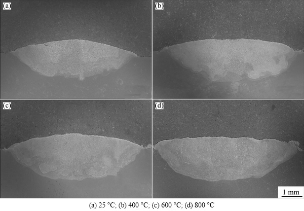
Fig. 3 Morphologies of cross-sections of coatings heated at different temperatures
3.3 Microstructural characterization
Figure 4 shows the representative microstructures of the cross-sections of the four coatings. The microstructures in the four coatings are also extremely similar. A large number of acicular structures are uniformly distributed in the matrix of the coatings.
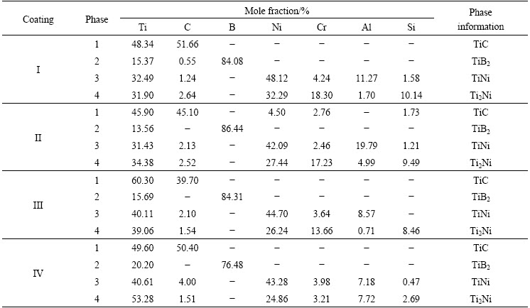
To observe the structures in detail, images with higher magnification are shown in Fig. 5. The structure is composed of two kinds of phases with different morphologies. Numerous fine grey strip-shaped/spherical particles (phase 1) are uniformly dispersed within the block acicular particle (phase 2). The compositions of the two phases were analyzed by EDS and the results are shown in Table 1. Phase 1 is rich in Ti and C in the four coatings and their compositions are very similar. Combined with the results of the XRD analysis, it can be identified as TiC, whereas, phase 2 only consists of Ti and B and can be regarded as TiB2. Therefore, the structure can be regarded as the eutectic of TiB2 and TiC. The matrix in the coatings is mainly composed of the gray-white cupped (phase 3) and the light-gray protuberant (phase 4) structures. As shown in Table 1, the two phases mainly contain Ti and Ni elements (the mole ratios of Ti to Ni in phases 3 and 4 are approximately 3:4 and 5:3, respectively), accompanied by a small quantity of Cr, Al and Si elements. The atomic radii of Ti, Ni, Cr, Al and Si are 2.00, 1.62, 1.85, 1.82 and 1.46  , respectively. The electronegativity values of the above five kinds of atoms are 1.54, 1.92, 1.66, 1.61 and 1.90, respectively. Regardless of the atomic radii and electronegativity values, Cr and Al are closer to Ti, and Si is closer to Ni. Therefore, Ti and Ni are easily replaced by Cr/Al and Si, respectively. As listed in Table 1, the sum of mole fraction of Ti, Cr and Al in phase 3 is 48.00%, and that of Ni and Si is 49.70%. Thus, phase 3 can be identified as the TiNi solid solution. The mole ratio of (Ti+Al+Cr) to (Ni+Si) in phase 4 is 1.94:1, so phase 4 can be considered as the Ti2Ni solid solution.
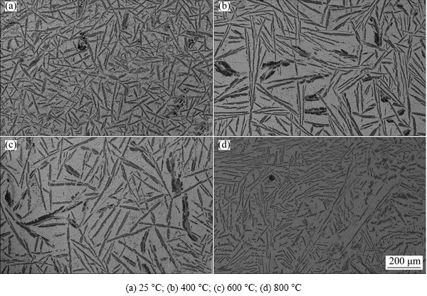
Fig. 4 Microstructures of cross-sections of coatings heated at different temperatures
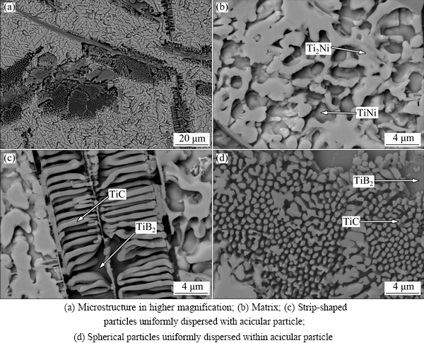
Fig. 5 Typical microstructures of cross-section of coating I
Table 1 Results of EDS analyses
3.4 Nanoindentation tests
Figure 6 shows the load-depth curves of the coatings prepared at different environmental temperatures. The curves clearly show the loading and unloading processes. The load applied to the coating surface is gradually increased from 0 to 10 mN, during which the elastic and the plastic deformations are produced successively. The mutual role resulting from the two behaviors causes the nonlinear change between the load and the depth. The load is gradually decreased to zero in the subsequent unloading process, accompanied by the recovery of elastic formation while the plastic formation is retained. As a result, the indentation is formed.
The slope of the unloading curve is related to the elastic modulus of the coating. The large slope indicates that the coating possesses a high elastic modulus. The residual depth (hf) after unloading can be used to characterize the hardness of the coating, wherein the greater the residual depth is, the lower the hardness is. The load-depth curves obtained in different zones of the coating prepared at 25 ��C are very scattered, indicating that the microstructure is not very uniform. With increasing the environmental temperature, the curves gradually tend to overlap. Thus, the increase in environmental temperature contributes to improving the microstructural uniformity of the coatings.
At present, the Oliver-Pharr method is universally used to calculate the hardness (H) and elastic modulus (E) of the materials, where hf/hmax<0.7 is required. When hf/hmax>0.7, a significant error (even exceeding 50%) may be produced due to the serious pile-up deformation generated around the indentation edge. The values of hf/hmax in different zones of the coatings are listed in Table 2. All values are lower than 0.7.
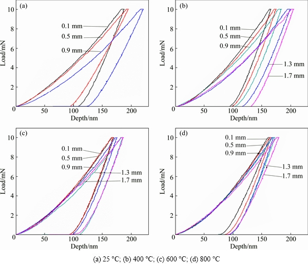
Fig. 6 Load-depth curves of coatings at different environmental temperatures
Table 2 hf/hmax values of coatings
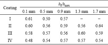
Figure 7 shows the two-dimensional and three- dimensional morphologies of the typical nanoindentation prepared in the zone with 0.9 mm distance from the surface of coating III. The zone around the nanoindentation is comparatively leveled and no obvious pile-up deformation is observed. Therefore, the hardness (H) and elastic modulus (E) of the coatings can be calculated by the following equations [23]:
 (7)
(7)
 (8)
(8)
where Pmax is the peak load, A is the projected contact area, S is the elastic contact stiffness, and b is a correction factor depending on the type of indenter (b=1.034 for the Berkovich indenter used in this study).
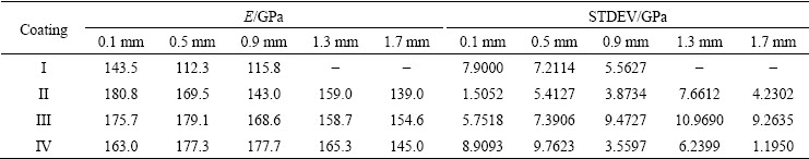
The calculated results are listed in Tables 3 and 4. The average hardness values of the four coatings are 10.67 GPa (25 ��C), 10.64 GPa (400 ��C), 10.96 GPa (600 ��C) and 11.82 GPa (800 ��C), with their average values of elastic modulus being 123.87 GPa (25 ��C), 158.26 GPa (400 ��C ), 167.34 GPa (600 ��C) and 165.66 GPa (800 ��C), respectively. It can be concluded that the environmental temperature has limited effects on the hardness and elastic modulus of the coatings.
High residual stress usually exists in the coating fabricated by laser cladding due to its rapid heating and cooling characteristics. As a result, the coating possesses a severe cracking susceptibility, which has become a critical issue hindering its application in industrial fields. Therefore, it is very necessary to characterize the residual stress in the coating.
At present, the Suresh model is commonly used to distinguish and calculate the residual stress of the material, which is mainly based on the difference in the maximum depth between a stress-free material and a material with residual stress. The model was presented to measure the residual stress using the nanoindentation method by SURESH and GIANNAKOPOULOS [24] in 1998. It can be applied to evaluating the residual stress in the materials with different thicknesses, from the thick coatings prepared by thermal spraying, high-energy beam treatment to the thin film materials prepared by PVD, CVD and magnetron sputtering, etc.
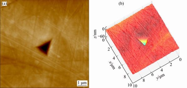
Fig. 7 Two-dimensional (a) and three-dimensional (b) morphologies of typical nanoindentation
Table 3 Average hardness values and their standard deviations (STDEV) of coatings in zones with different distances from surface of coatings
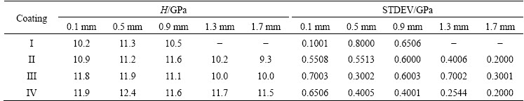
Table 4 Average values of elastic modulus and their standard deviations (STDEV) of coatings in zones with different distances from surface of coatings
In previous decades, numerous studies were conducted to measure the residual stress of the thick coatings by the nanoindentation method. WANG et al [25] determined the residual stress in the plasma sprayed Fe-based coating with the thickness of about 200 mm by the nanoindentation method. Residual stress with a value of 188 MPa was obtained, which corresponded well with the value (162 MPa) measured by the XRD method. DEY and MUKHOPADHYAY [26] prepared the bioactive hydroxyapatite (HAP) ceramic coatings with the thickness of about 1 mm on 316 L austenitic stainless steel and Ti6Al4V substrates by the micro-plasma spraying (MIPS) technique. The residual stress in the coatings was calculated by the nanoindentation method. The results showed a residual compressive stress of approximately 22 MPa existed in the MIPS-HAP coating prepared on the SS316L substrate. However, for the MIPS-HAP coatings deposited on the Ti6Al4V substrate, a residual tensile stress of approximately 11 MPa was estimated. These data matched well with those obtained via the XRD technique. LI [22] evaluated the residual stress in the Fe314 coating with the thickness of about 2 mm prepared on the surface of 1045 steel by plasma cladding. The coatings were annealed at different annealing temperatures (500, 600 and 800 ��C), respectively. The residual stress in the coatings was calculated by the XRD method and the nanoindentation method. The results showed that the residual stress in the coatings annealed at 600 and 800 ��C was close to zero, while the large residual stress (about 550 MPa) existed in the coating without annealing treatment. In addition, the residual stresses obtained by Suresh model [24] were more consistent those obtained by the XRD method, compared with those obtained by the Yun-Hee Lee model. Those studies indicate that the model is suitable to measure the residual stress existing in the thick coating.
To avoid the disturbance of the microstructural difference on the maximum depth of the indentation, the model theoretically requires the materials without or with the residual stress to possess the same microstructure. As analyzed above, the microstructures of the coatings prepared at different environmental temperatures are closely similar. The changes in the maximum depth of the nanoindentations are mainly attributed to the difference in residual stress. Therefore, the Suresh model can be adopted to calculate the residual stress of the coatings. When a stress-free sample is confirmed, the stress in other samples can be evaluated by the following equations [24,27]:
For the residual tensile stress, we have
 (9)
(9)
For the residual compressive stress, we have
 (10)
(10)
where h and h0 are the penetration depths in the samples with and without the residual stress, respectively, H is the hardness of the samples, and �� is related to the indentation angle of the indenter. For a Berkovich indenter, ��=24.7��.
The residual stresses in the clad coating mainly include thermal stress, structural stress and restrain stress. Among them, the thermal stress is predominant, which depends on the difference between the environmental and cladding temperatures. In this work, the coatings were prepared at 25, 400, 600, and 800 ��C, respectively. According to the fundamental theories of material science, the residual stress in the coating can be reduced by decreasing the difference between the environmental and cladding temperatures. Moreover, the test results also further confirm this. As shown in Fig. 8 (the load-depth curves obtained in different zones of the four coatings), the slopes of the loading curves approximately present the rise trend with the increase in environmental temperature. This indicates that more residual stress is relieved by increasing the environ- mental temperature. Therefore, the coating prepared at 800 ��C is selected as the stress-free coating. As shown in Fig. 8(a), the load-depth curves of the coatings with stress are located below that of the stress-free coating. The maximum depth presents the increasing trend with the decrease in environmental temperature. Especially for the coating prepared at 25 ��C, it reaches 188 nm, which is much larger than those obtained in other coatings. When the same load is applied to the coating, the tensile stress tends to promote the formation of an indentation with a large depth. The compressive stress will produce the contrary effect in the coating. Therefore, it is concluded that the tensile stress exists in the coatings. Further, as shown in Figs. 8(b)-(e), the load-depth curves obtained in other zones of the coatings follow the same pattern. The generation of the residual tensile stress will increase the cracking susceptibility of the coatings [27].
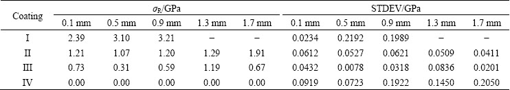
The residual tensile stress (��R) in the coatings was calculated by the Suresh model (shown in Table 5). To compare the change in residual stress in the zones equidistant from different coating surfaces, every testing zone in the coating prepared at 800 ��C is regarded as the stress-free zone. The average value of residual tensile stress in the coating prepared at 25 ��C is the largest (approximately 2.90 GPa). With increasing the environmental temperature, the average value is reduced to 1.34 GPa (400 ��C), 0.70 GPa (600 ��C), and 0 GPa (800 ��C). When the environmental temperature rises every 200 ��C, the residual tensile stress is decreased by approximately 50%. Thus, the rise in environmental temperature will contribute to the reduction in residual tensile stress in the coatings.
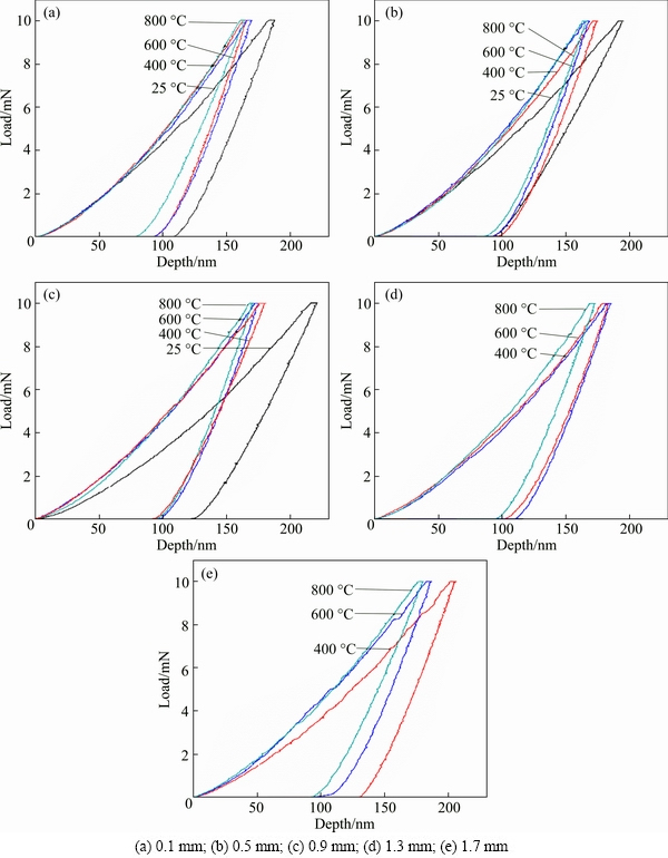
Fig. 8 Load-depth curves obtained in different zones of coatings
Table 5 Residual stress (��R) and its standard deviation (STDEV) in different zones of coatings (Every testing zone in coating IV as stress-free zone)
Similar results were reported by various researchers. WU et al [28] discussed a finite element model established using the ANSYS software for the single- track laser clad Al2O3 ceramic coating prepared on the Ti6Al4V substrate. The results showed that preheating the substrate could sharply reduce the temperature gradient. Therefore, it was effective to restrain the crack formation by preheating the substrate. LI et al [29] studied the temperature and stress fields in the laser clad Ni-WC-Cr3C2 ceramic coating using SYSWELD software. The cooling velocity of the coating was decreased with increasing the preheating temperature. The residual stress in the coating was significantly decreased when the substrate was preheated above 350 ��C. FALLAHI et al [30] effectively reduced the residual stress generated in the welding process by introducing the preheating treatment. ZHANG et al [31] prepared the coating by laser cladding the Colmonoy 6 powder on the AISI316L austenitic stainless steel. The number of cracks was decreased obviously with increasing the preheating temperature. Furthermore, when the preheating temperature reached 450 ��C, no cracks were observed. LIANG et al [32] designed a substrate preheating system for laser cladding based on the heat conducting theory and laser rapid prototyping theory. The Ni60A powder was selected as the cladding material, and the substrate was preheated to 25, 200, 400, 500 and 580 ��C, respectively. The results showed that the substrate preheating can significantly decrease the thermal stress and the initiation of cracks in the shaping process. WANG et al [33] prepared the Cr13Ni5Si2- based composite coatings by laser-induction hybrid cladding (LIHC). The residual stress in the coatings was characterized by the X-ray diffraction method. The results revealed that the residual stress in the coatings belonged to the tensile stress. When the preheating temperature reached 850 ��C, the residual tensile stress in the coatings was reduced to the minimum value, and the average values in the longitudinal and the transverse axes were 284.0 and 256.0 MPa, respectively. When the preheating temperature was decreased to 750 and 650 ��C, the residual tensile stresses in the longitudinal axis and the transverse axis were increased to 333.0 and 282.0, 434.4 and 372.4 MPa, respectively. Furthermore, when the preheating temperature was lower than 650 ��C, numerous cracks were formed along the surfaces of the coatings. Thus, preheating the substrate was a useful method to reduce the residual stress in the coatings.
Table 6 Residual stress (��R) and its standard deviation (STDEV) in different zones of coatings (Zone with distance of 0.1 mm from surface of coating IV as stress-free zone)
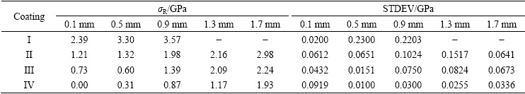
To compare the changes in residual stress along the depth direction of one specific coating, the zone with a distance of 0.1 mm from the surface of the coating prepared at 800 ��C was selected as the stress-free zone. As shown in Table 6, the residual tensile stress is increased with increasing the distance from the coating surface. The similar conclusions were also drawn by several researchers. ZHU et al [19] investigated the distribution of residual stress in the laser clad Fe-based coating. The result showed that the residual stress was gradually increased from 200 to 700 MPa with respect to the increase in distance from the coating surface. REN et al [34] investigated the stress distribution law in the laser clad Fe314 alloy coatings prepared on 45 steel. The stress distribution in the coatings was analyzed using the X-ray diffraction method. The lowest tensile stress of 200 MPa was measured on the coating surface. With increasing the depth, the residual tensile stress was gradually increased from 200 to 400 MPa.
The tensile stress distribution along the coating depth is mainly related to the change in temperature gradient in the coating. Due to the higher heat conductivity of the substrate (5.44 W/(m��K)) than that of air (0.0243 W/(m��K)) at room temperature, the temperature gradient in the lower zone of the molten pool close to the substrate is greater than that in its upper zone during the subsequent solidification. As a result, the residual tensile stress presents a gradually increasing tendency along the depth direction of the coatings.
4 Conclusions
1) The TiNi/Ti2Ni dual-phase coatings reinforced by TiB2 and TiC on the Ti6Al4V substrate were prepared by laser cladding at different environment temperatures of 25, 400, 600 and 800 ��C. The microstructures in the four coatings were exactly similar. The coatings were mainly composed of TiNi/Ti2Ni as the matrix and TiC/TiB2 as the reinforcement.
2) The residual tensile stress was generated in the coatings during laser cladding. The environment temperature directly influenced the residual stress in the coatings. When the coating prepared at 800 ��C was selected as the stress-free coating, the residual stress in the coatings prepared at 25, 400 and 600 ��C was the tensile stress. And the residual tensile stress was increased with the decrease in environmental temperature (0.70 GPa at 600 ��C, 1.34 GPa at 400 ��C, 2.90 GPa at 25 ��C). For a specific coating, the residual tensile stress was increased with the increase in distance from the coating surface.
3) Laser cladding at high temperatures can effectively reduce the cracking susceptibility of the coating.
References
[1] LU Shi-qiang, YANG De-lai, CUI Xia, WANG Ke-lu. Dynamic recrystallization behavior of burn resistant titanium alloy Ti-25V-15Cr-0.2Si [J]. Transactions of Nonferrous Metals Society of China, 2016, 26: 1003-1010.
[2] LIU Xiu-bo, MENG Xiang-jun, LIU Hai-qing, SHI Gao-lian, WU Shao-hua, SUN Cheng-feng, WANG Ming-di, QI Long-hao. Development of characterization of laser clad high temperature self-lubricating wear resistant composite coatings on Ti-6Al-4V alloy [J]. Materials and Design, 2014, 55: 404-409.
[3] WANG Qin-ying, BAI Shu-lin, LIU Zong-de. Corrosion behavior of Hastelloy C22 coating produced by laser cladding in static and cavitation acid solution [J]. Transactions of Nonferrous Metals Society of China, 2014, 24: 1610-1618.
[4] GONG FU-bao, SHEN Jun, GAO Run-hua, ZHANG Tao, XIE Xiong, LI Yang. Influence of heat treatment on microstructure and mechanical properties of FeCrNi coating produced by laser cladding [J]. Transactions of Nonferrous Metals Society of China, 2016, 26: 2117-2125.
[5] LONG Yi-tong, NIE Pu-lin, LI Zhu-guo, HUANG Jian, LI Xiang, XU Xin-mei. Segregation of niobium in laser cladding Inconel 718 superalloy [J]. Transactions of Nonferrous Metals Society of China, 2016, 26: 431-436.
[6] WANG Dong-sheng, LIANG Er-jun, CHAO Ming-ju, YUAN Bin. Investigation on the microstructure and cracking susceptibility of laser-clad V2O5/NiCrBSiC alloy coatings [J]. Surface & Coatings Technology, 2008, 202: 1371-1378.
[7] WENG Fei, YU Hui-jun, CHEN Chuan-zhong, LIU Jian-li, ZHAO Long-jie. Microstructures and properties of TiN reinforced Co-based composite coatings modified with Y2O3 by laser cladding on Ti6Al4V alloy [J]. Journal of Alloys and Compounds, 2015, 650: 178-184.
[8] RIQUELME A, RODRIGO P, RAMS J. Analysis and optimization of process parameters in Al-SiCp laser cladding [J]. Optics and Lasers in Engineering, 2016, 78: 165-173.
[9] ZHOU Sheng-feng, ZENG Xiao-yan, HU Qian-wu, HUANG Yong-jun. Analysis of crack behavior for Ni-based WC composite coatings by laser cladding and crack-free realization [J]. Applied Surface Science, 2008, 255: 1646-1653.
[10] FALLAH V, ALIMARDANI M, CORBIN S F, KHAJEPOUR A. Impact of localized surface preheating on the microstructure and crack formation in laser direct deposition of Stellite 1 on AISI 4340 steel [J]. Applied Surface Science, 2010, 257: 1716-1723.
[11] LESTAN Z, MILFELNER M, BALIC J, BREZOCNIK M, KARABEGOVIC I. Laser deposition of Metco 15E, Colmony 88 and VIM CRU 20 powders on cast iron and low carbon steel [J]. The International Journal of Advanced Manufacturing Technology, 2013, 66: 2023-2028.
[12] HUANG C J, CHENG C M, CHOU C P, CHEN F H. Hot cracking in AZ31 and AZ61 magnesium alloy [J]. Journal of Materials Science & Technology, 2011, 27(7): 633-640.
[13] EVANS A G, WILSHAW T R. Quasi-static solid particle damage in brittle solids��I. Observations analysis and implications [J]. Acta Metallurgica, 1976, 24: 939-956.
[14] LAVIGNE O, GAMBOA E, COSTIN W, LAW M, LUZIN V, LINTON V. Microstructural and mechanical factors influencing high pH stress corrosion cracking susceptibility of low carbon line pipe steel [J]. Engineering Failure Analysis, 2014, 45: 283-291.
[15] CHEN Jia-li, LI Jun, SONG Rui, BAI L��-lin, SHAO Jin-zhong, QU Cui-cui. Effect of the scanning speed on microstructural evolution and wear behaviors of laser cladding NiCrBSi composite coatings [J]. Optics and Lasers in Engineering, 2015, 72: 86-99.
[16] MASANTA M, SHARIFF S M, ROY CHOUDHURY A R. Evaluation of modulus of elasticity, nano-hardness and fracture toughness of TiB2-TiC-Al2O3 composite coating developed by SHS and laser cladding [J]. Materials Science and Engineering A, 2011, 528: 5327-5335.
[17] WU Zhi, ZHOU Jing, CHEN Wen, SHEN Jie, Chun, QI Yan-yuan. Detection of residual stress in Ba(Mg1/3Ta2/3)O3 thin films by nanoindentation technique [J]. Ceramics International, 2015, 41: 11632-11636.
[18] DEAN J, ALDRICH-SMITH G, CLYNE TW. Use of nanoindentation to measure residual stresses in surface layers [J]. Acta Materialia, 2011, 59: 2749-2761.
[19] ZHU Li-na, XU Bin-shi, WANG Hai-dou, WANG Cheng-biao. Microstructure and nanoindentation measurement of residual stress in Fe-based coating by laser cladding [J]. Journal of Materials Science, 2012, 47: 2122-2126.
[20] WANG An-ni, HUANG Jia-hong, HSIAO Haw-wen, YU Ge-ping, CHEN Haydn. Residual stress measurement on TiN thin films by combing nanoindentation and average X-ray strain (AXS) method [J]. Surface & Coatings Technology, 2015, 280: 43-49.
[21] KHAN M K, FITZPATRICK M E, HAINSWORTH S V, EDWARDS L. Effect of residual stress on the nanoindentation response of aerospace aluminium alloys [J]. Computational Materials Science, 2011, 50: 2967-2976.
[22] LI Hua-yi. Indentation testing of residual stress and its mechanics for remanufacturing surface coatings [D]. Tianjin: Hebei University of Technology, 2011: 1-79. (in Chinese)
[23] VOYIADJIS G Z, PETERS R. Size effects in nanoindentation: An experimental and analytical study [J]. Acta Mechanica, 2010, 211: 131-153.
[24] SURESH S, GIANNAKOPOULOS A E. A new method for estimating residual stresses by instrumented sharp indentation [J]. Acta Materialia, 1998, 46(16): 5755-5767.
[25] WANG Hai-dou, ZHU Li-na, XU Bin-shi. Measurement of residual stress of plasma sprayed Fe-based coating by nanoindentation [J]. Journal of Mechanical Engineering, 2013, 49(7): 1-4. (in Chinese)
[26] DEY A, MUKHOPADHYAY A K. Evaluation of residual stress in microplasma sprayed hydroxyapatite coating by nanoindentation [J]. Ceramics International, 2014, 40: 1263-1272.
[27] ZHU Li-na. Research on residual stresses of coatings by nanoindentation technology [D]. Beijing: China University of Geosciences, 2013: 1-109. (in Chinese)
[28] WU Dong-jiang, WU Nan, YANG Che, MA Guang-yi, KANG Ren-ke. Numerical simulation of the preheating effect on temperature gradient in laser cladding Al2O3 ceramic [J]. Rare Metal Materials and Engineering, 2013, 42(10): 2039-2042.
[29] LI Mei-yan, CAI Chun-bo, HAN Bin, WANG Yong. Numerical simulation of preheating on temperature and stress fields by laser cladding Ni-based ceramic coating [J]. Transactions of Materials and Heat Treatment, 2015, 36(12): 197-203.
[30] FALLAHI A, JAFARPUR K, NAMI M R. Analysis of welding conditions based on induced thermal irreversibilities in welded structures: Cases of welding sequences and preheating treatment [J]. Scientia Iranica, 2011, 18(3): 398-406.
[31] ZHANG Hong, SHI Yan, KUTSUNA M, XU Guo-jian. Laser cladding of Colmonoy 6 powder on AISI316L austenitic stainless steel [J]. Nuclear Engineering and Design, 2010, 240: 2691-2696.
[32] LIANG Zhi-hong, MA En-bo. Structural design of substrate preheating for laser cladding [J]. Machinery Design & Manufacture, 2009, 7: 54-56. (in Chinese)
[33] WANG Deng-zhi, HU Qian-wu, ZENG Xiao-yan. Residual stress and cracking behaviors of Cr13Ni5Si2 based composite coatings prepared by laser-induction hybrid cladding [J]. Surface & Coatings Technology, 2015, 274: 51-59.
[34] REN Wei-bin, DONG Shi-yun, XU Bin-shi, WANG Yu-jiang, YAN Shi-xing, FANG Jin-xiang. The law of stress distribution of the laser cladding layer of Fe314 alloy [J]. China Surface Engineering, 2013, 26(3): 58-63. (in Chinese).
��ͬ�����¶����Ʊ���TiNi/Ti2Ni�������۸�Ϳ���в�ͬ�������IJ���Ӧ���ֲ�
�����棬�� ������Ӣ�������з�
�Ϻ����̼�����ѧ ���Ϲ���ѧԺ���Ϻ� 201620
ժ Ҫ�����о���Ŀ����ͨ��������¶����������ͼ����۸�Ϳ��Ŀ��������ԣ�����ʾ�����۸�Ϳ���в�ͬ�������IJ���Ӧ���ֲ����ɡ���25��400��600�� 800 ��C �����¶���ͨ�������۸�������Ti6Al4V�������Ʊ���TiB��TiC��ǿ��TiNi/Ti2Ni˫�������Ϳ�㡣ͨ������ѹ�۷���ϸ������Ϳ�㲻ͬ����������Ӧ���ı仯����������ʾ����25 ��C �����¶����Ʊ���Ϳ����ƽ��������Ӧ����ﵽ2.90 GPa�����Ż����¶ȵ����ߣ�Ϳ���е�ƽ������Ӧ�����½���1.34 GPa (400 ��C)��0.70 GPa (600 ��C) �� 0 GPa (800 ��C)����������Ϳ�㣬������Ӧ��������Ϳ���������������������¶ȵ��������Ч����Ϳ��Ŀ��������ԡ�
�ؼ��ʣ������۸���Ϳ�㣻����֯�������¶ȣ����������ԣ�����Ӧ��������ѹ�۷�
(Edited by Wei-ping CHEN)
Foundation item: Project (51471105) supported by the National Natural Science Foundation of China; Project (12SG44) supported by the ��Shu Guang�� Project of Shanghai Municipal Education Commission and Shanghai Education Development Foundation, China; Project (15KY0504) supported by the ��Graduate Innovation�� Project of Shanghai University of Engineering Science, China
Corresponding author: Jun LI; Tel: +86-13524458254; E-mail: jacob_lijun@sina.com
DOI: 10.1016/S1003-6326(17)60229-2
Abstract: This study aimed to effectively reduce the cracking susceptibility of the laser clad coating by enhancing the environmental temperature during laser cladding, and reveal the residual stress distribution in different depths of the coating. The TiNi/Ti2Ni-based coatings were prepared on Ti6Al4V by laser cladding at different environmental temperatures of 25, 400, 600 and 800 ��C. The changes in residual stress along the depth of the coatings were investigated in detail by the nanoindentation method. Results showed that the average residual stress of 2.90 GPa in the coating prepared at 25 ��C was largest. With the increase in environmental temperature, the average residual stress was reduced to 1.34 GPa (400 ��C), 0.70 GPa (600 ��C) and 0 GPa (800 ��C). For all the coatings, the residual stress was increased with increasing the distance from the coating surface. Enhancing the environmental temperature can effectively reduce the cracking susceptibility of the coatings.
