
Trans. Nonferrous Met. Soc. China 26(2016) 1359-1366
Effect of milling energy on preparation of Cu-Cr/CNT hybrid nano-composite by mechanical alloying
M. MASROOR, S. SHEIBANI, A. ATAIE
School of Metallurgy and Materials Engineering, College of Engineering,
University of Tehran, P. O. Box 11155-4563, Tehran 13145-1318, Iran
Received 4 June 2015; accepted 6 January 2016
Abstract:
Production of Cu-Cr/carbon nanotube (CNT) hybrid nano-composite by wet and dry milling processes at three different levels of milling energy was investigated in order to study the effect of milling energy in two different media on dispersion of CNTs, and preparation of the nano-composite. The structural evolution and solid solution formation were evaluated by X-ray diffraction technique. The microstructure was characterized by scanning electron microscopy and transmission electron microscopy. Also, the mechanical properties were measured by microhardness test. The mean crystallite size was in the range of 20-63 nm depending on milling medium and energy. CNTs dispersion is a function of milling energy. According to FESEM images and microhardness results, it can be concluded that wet milling is more applicable in dispersing CNTs homogeneously in comparison to dry milling. It was also found that wet milling at higher milling energies can be a beneficial method of producing the homogeneous hybrid nano-composite with the least damages introducing on CNTs because of the higher microhardness which can be attributed to better dispersion of less damaged CNTs. Compared with crystallite size changes, CNTs dispersion and damages were considerably more effective on hardness.
Key words:
carbon nanotubes; copper; nano-composite; mechanical alloying;
1 Introduction
Copper matrix hybrid composites reinforced with ceramic and metallic precipitates, have received considerable interest in researches due to their favourable properties, namely good mechanical properties, high electrical and thermal conductivity. Among copper matrix composites Cu-Cr is an in situ composite. Cr has a small solid solubility in Cu matrix because of its positive heat of mixing which results from decomposition of supersaturated Cu-Cr solid solution [1-3]. Extension of Cr solubility in Cu during mechanical alloying and the effect of Al2O3 nano-particles on the Cr solubility have already been investigated [4,5]. On the other hand, carbon nanotubes (CNTs) are good candidates to be used as reinforcements in polymer, ceramic and metallic composites due to their valuable properties. For example, they are reported to have an elastic modulus equal to 1.2 TPa which is comparable to that of diamond and a strength about 10-1000 times that of high strength steel [6]. So far, most of the investigations on CNT composites have been focused on polymer matrix composites and ceramic matrix composites compared with metal matrix composites because of difficulty in homogeneous dispersion of CNTs in the metal matrix due to their agglomeration, density mismatch and weak interface bonding with metallic matrices [7]. In recent years, some studies have been carried out on Cu/CNT systems related to these problems [6,8-12]. Cu/CNT composites can be prepared by different methods. KIM et al [8] prepared Cu/CNT nano-composite by molecular level mixing which showed a homogeneous dispersion of CNTs in the Cu matrix. CHU et al [9] mixed the powders by particles composing system and then consolidated the powders by spark plasma sintering for producing Cu/CNT composite. TSAI and JENG [10] have fabricated Cu/CNT composites by using a unique powder consolidation and high pressure torsion techniques and showed that the buckling behaviour of CNTs played a pivotal role in mechanical properties of the composite. CHU et al [11] also prepared Cu-Cr/CNT composites by using Cr as an alloying element for improving the interface strength of Cu and CNT by the formation of thin intermediate Cr3C2transition layer at the interface. Beside usage of CNTs Cu/SiC-CNT as a reinforcing element, it is possible to use a second element to investigate its effects on the characteristics of the nano-composite. Recently, AKBARPOUR et al [6] have prepared hybrid composites via mechanical alloying and hot pressing method. They showed that in the presence of SiC nano-particles, CNTs were dispersed homogeneously and the mechanical properties were enhanced considerably.
Among different approaches for fabricating hybrid nano-composites, ball milling is a simple, low cost and high yield method. Also, it is an efficient way for producing CNT strengthened alloys due to the possibility of dispersing carbon nano-tubes as reinforcement elements in metal matrix composites [10,13,14]. Despite these advantageous, agglomeration and defects that are introduced on CNTs during ball milling will affect their morphology, mechanical and physical properties [15,16]. Wet milling in the presence of a liquid phase [17,18] and several surface modification or functionalization techniques has been used to enhance the dispersion of CNTs [19]. However, functionalization requires good knowledge of surface chemistry of CNTs and may be a time consuming method in comparison with wet ball milling. SOTOUDEHNIA and PAUL [20] added treated CNTs to Fe matrix and wet milled the mixture and showed that this process ensured a homogeneous dispersion of CNTs in the matrix which would enhance the properties of final product. Also, ZHOU et al [17] could uniformly disperse CNTs into nano-sized Sb particles via wet milling in acetone. Although relatively few studies [17,20] have been directed towards CNTs dispersion in metal matrix composites through wet mechanical milling, there was no detailed study that was carried out on the optimization of dry and wet ball milling conditions in Cu-Cr/CNT hybrid nano- composite. Specially, the comparative study on CNTs dispersion in Cu-Cr matrix from a milling energy viewpoint, which has not been studied yet, seems interesting. In this work, the preparation of Cu-1%Cr/5%CNT hybrid nano-composite by dry and wet ball milling was compared. Also, the effect of milling energy on CNTs dispersion, structural and microstructural evolution and mechanical property has been investigated.
2 Experimental
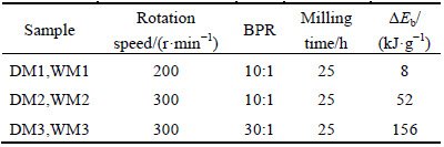
Starting materials used in this work were commercially pure Cu (99.5%, <75 ��m), Cr (99.5%, <75 ��m) and multi-walled CNTs (~10 ��m in length, and 10-30 nm in diameter) with purity of about 90%. It should be mentioned that CNTs were sonicated in ethanol for 90 min, to break up the CNTs agglomerates. Powder mixtures were mechanically milled in a planetary high energy ball mill (PM2400) with hardened steel vial (volume of 300 mL) and 7 balls (diameter of 20 mm) under argon atmosphere. In the first step, Cu-1%Cr solid solution was prepared as the matrix phase. The ball-to-powder mass ratio (BPR) and milling speed were 30:1 and 300 r/min, respectively. 1% of toluene was used as a process control agent. Milling was conducted up to 30 h. From the X-ray diffraction (XRD) results reported here, it is established that 20 h milling was sufficient to reach steady state in Cu-Cr solid solution formation. In the second step, Cu-Cr solid solution alloy together with 5% of CNTs was dry milled for 5 h. Three different milling conditions were tested to reveal the effect of milling energy on dispersion of CNTs. Also, the same sample conditions as dry milling were wet milled in 10 mL of ethanol with purity of 99.7% to evaluate the effectiveness of wet milling medium. The milled samples were dried on hotplate at 80 ��C for about 1 h to evaporate the ethanol. Table 1 summarizes milling conditions of different samples.
Table 1 Milling conditions of different samples

The structural evolution in the powder during milling was investigated by XRD using a Philips PW3170 X-ray diffractometer with Cu K�� radiation. The lattice parameters were calculated from XRD data [1]. The mean crystallite size was determined according to the Williamson-Hall plot [21]. The microstructure was evaluated by a CamScan MV2300 field emission scanning electron microscope. SEM and transmission electron microscopy (TEM) (Philips CM30) were used to study the microstructure. To evaluate the Vickers microhardness of samples, microhardness tester of the model WOLPERT-WERKE GMBH D-6700 was used. At first, the powders were mounted and then polished. The measurement was performed with a load of 100 g for 15 s. The test was repeated 10 times at different points in each sample and the average of these 10 points was reported as microhardness of each sample.
3 Theory and calculation
To investigate the effect of milling parameters on the dispersion of CNTs, the total milling energy transferred to powders during ball milling was calculated. Two energy parameters should be considered in milling energy calculations, one is impact energy of each ball (��Eb), the other is the total energy transferred to the powder after a certain milling time (��Et) which is categorized in three levels in this study. ��Eb is given by [22]
��Eb=1/2mb(Vb2-Vs2) (1)
where mb is the mass of a ball, Vb and Vs are the absolute velocities before and after the hit, respectively. BURGIO et al [23] have presented collision model by which it is possible to calculate Vb and Vs by milling parameters. According to this model, ��Eb can be calculated as
��Eb=-mb[��v3(Rv-rb)/��p+��p��vRp](Rv-rb) (2)
where ��p and ��v are the absolute angular velocity of mill plate and one vial, respectively; Rp, Rv and rb are the radii of plate, vial and ball, respectively. When Nb balls are present in the vial, the energy released by each ball is given by
��Eb*=��b��Eb (3)
where ��b<1 is empirical factor for different degrees of filling of the vial [23]. To define ��b, we should consider the bellow expression:
��b=(1-nv��) (4)
Actually, ��b is a function of two parameters nv and ns:
nv=Nb/Nb,v (5)
where Nb,v is the number of balls that can be contained in a simple cubic arrangement in the vial and is given by
Nv,b=��Dv2Hv/(4db3) (6)
Dv and Hv are the diameter and the height of the vial, and db is the ball diameter:
ns=Nb/Nb,s (7)
where Nb,s is the number of balls needed to cover, in a simple cubic arrangement, one third of the inner surface wall is given by
Nb,s=��(Dv-db)Hv/(3db2) (8)
In ��b expression, �� is a parameter which depends on the ball diameter that can be evaluated by this equation:
0.95=[1-(Nb,v/Nb,s)��] (9)
Finally, ��Et for a given time can be expressed as
��Et=��Eb*Nbfbt/Wp (10)
where Wp is the mass of powders in the vial and fb is the frequency of impact according to BURGIO et al [23] can be expressed by
fb=k(��p-��v)/2�� (11)
where k is the proportionality constant and approximately equals 1. The total energy is calculated for the three chosen levels of milling energy, namely low energy (200 r/min, BPR=10:1), medium energy (300 r/min, BPR=10:1) and high energy (300 r/min, BPR=30:1) which are presented in Table 2. In this work, the suggested categories of milling energy are according to the milling conditions. It should be mentioned that two factors which play an important role in milling energy are BPR and milling speed. According to the Ref. [24], the suggested values of BPR and milling speed have relatively low, medium and high levels. Hence, the calculated milling energies were categorized correspondingly. On the other hand, similar principle has been reported by HODAEI et al [25], RAGAB and SALEM [26], TORKAN et al [27], AHMADZADEH et al [28] and GUZMAN et al [29] based on milling conditions such as BPR and milling speed to categorize milling energies to these levels.
Table 2 Milling condition and calculated milling energy of samples
4 Results and discussion
Figure 1 shows XRD patterns of Cu-1%Cr powder mixture milled for various time. It can be seen that compared with initial powder, the Cu peaks broadened on increasing milling time since the continuous deformation of powder particles during the milling process results in crystallite refinement and formation of structural defects [24]. Also, a shift of the Cu peaks to lower angles was observed, which is related to the increase of the lattice parameter [24]. In order to understand the formation of the Cu-1%Cr solid solution, the Cu lattice parameter was determined.
Figure 2 shows lattice parameter of Cu as a function of milling time. Large increase in lattice parameter of Cu with increasing milling time from 0 to 20 h, suggests that Cu-1%Cr solid solution forms in this period of time. Furthermore, the final lattice parameter of the sample milled for 20 h is in good agreement with the previous relationship between the lattice parameter and alloy composition established for supersaturated solid solution samples produced by rapid solidification [1].
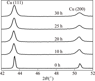
Fig. 1 XRD patterns of Cu-1%Cr powder mixtures after different milling time
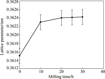
Fig. 2 Lattice parameter of Cu as function of milling time
Based on the results of the first milling step, 5% of CNTs were added to 20 h milled Cu-Cr solid solution sample and milling was continued for 5 h in both wet and dry milling media. Figure 3 shows XRD patterns of DM2 and WM3 samples in comparison with 20 h milled Cu-Cr solid solution. Each was selected from dry and wet groups of samples. It should be noted that XRD results in different milling conditions did not show an obvious change, and similar results were obtained.
For more detailed study on the effect of milling conditions on the Cu structure, the Cu lattice parameter and mean crystallite size changes as a function of milling energy for different samples are shown in Fig. 4. Cu lattice parameters changes in Fig. 4(a) confirmed that the lattice parameters are approximately constant of about 0.3625 nm. This indicates that CNTs do not significantly affect the solubility of Cr in Cu lattice in both dry and wet milling processes. The mean crystallite sizes of Cu for above mentioned samples are illustrated in Fig. 4(b). It can be found that, the crystallite size of both dry and wet milled samples decreases as the milling energy increases. However, in wet milled samples due to the presence of ethanol, less energy is attributed to the change in crystallite size. Therefore, the mean crystallite size of wet milled samples is larger than that of dry milled ones.

Fig. 3 XRD patterns of DM2 and WM3 samples compared with 20 h milled samples
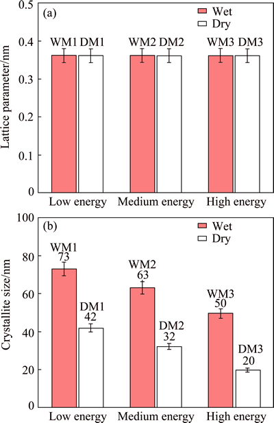
Fig. 4 Changes of lattice parameter (a) and crystallite size (b) as function of milling energy for different samples
Figure 5 shows the FESEM images of dry milled samples for different levels of milling energy. Figure 5(a) shows the microstructure of DM1 sample. At this low level of milling energy, the CNTs are not embedded in the matrix and due to the lack of enough energy for dispersion, CNT agglomerates can be found. Figure 5(b) shows the microstructure of DM2 sample. It is obvious that medium level of energy can be efficient in dispersing CNTs in the matrix during dry milling, since CNTs agglomerates were not observed. Also, CNTs are fully embedded in the matrix as it is marked by arrows. Figure 5(c) shows the microstructure of DM3 sample. Because of higher milling energy that is transferred to the powder mixture, CNTs are broken. The broken ends of CNTs agglomerates which are not embedded can be seen at higher magnification in the inset (as it is marked by arrows). Actually, it can be seen that CNTs are not embedded in the matrix while they are broken. Hence, dry milling at medium level of energy can be efficient for reaching perfectly embedded CNTs in the matrix with the least damages introduced on them.

Fig. 5 FESEM images of DM1 (a), DM2 (b) and DM3 (c) samples
Figure 6 shows FESEM images of wet milled samples. Figure 6(a) shows the microstructure of WM1 sample. As mentioned above, energy at this level is not enough, so CNTs are not perfectly embedded in the matrix. Figure 6(b) shows FESEM image of WM2 sample. At medium levels of milling energy, CNTs are embedded better compared with low milling energy. But the energy is still insufficient for perfect embedding. Figure 6(c) is related to high energy milled powders. It shows FESEM of WM3 sample that CNTs are tightly embedded in the structure. Accordingly, wet milling at high levels of milling energy can be considered as the most efficient way to reach perfectly embedded CNTs. It should be noted that, owing to the collision of the balls, the ductile Cu particles were deformed and flake-like particles were produced in all samples. In fact, flattened Cu flakes are laid and welded on each other and larger particles formed.

Fig. 6 FESEM images of WM1 (a), WM2 (b) and WM3 (c) samples
Figure 7 shows microhardness values of powders. The microhardness of dry milled samples decreases with increasing milling energy; conversely, the microhardness of wet milled samples increases at higher milling energy. Although it was expected to reach higher microhardness values in dry milled samples due to their smaller mean crystallite size, the values are in lower range. This indicates that, improved dispersion of CNTs and less damage introduced on them are more effective than crystallite size reduction. In other words, in wet milling process a high proportion of energy is allocated to dispersion of CNTs and crystallite size is not affected much.
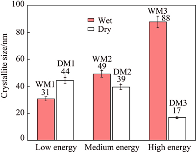
Fig. 7 Microhardness values of different samples as function of milling energy
According to the literatures [22,23,25-30], the effect of milling medium has not been considered on milling energy formula by any terms or factors. However, according to a modelling by KARUNATILAKE et al [30], the effect of buoyancy and Stokes forces in ball milling with suspension were studied. It can be concluded that during wet milling, approximately 11% of milling energy is transferred to the powder. Our results are in agreement with this result. In fact, comparison of crystallite size, FESEM images and microhardness results of dry and wet milling showed that wet milling higher energy is required to disperse the CNTs in the matrix more efficiently. It may be suggested that energy loss was due to the influence of the suspension in wet milling.
In order to get a better understanding of the CNTs dispersion in the Cu-Cr solid solution matrix, the microstructure of WM3 sample which shows optimized CNTs dispersion and maximum microhardness was investigated by TEM. Figure 8 shows the bright-field TEM image of WM3 sample. The embedded CNTs are marked by white arrows which are in agreement with FESEM and microhardness results. The TEM image of WM3 sample shows that the crystallites of mechanically alloyed product are in nano-metric scale and its mean crystallite size was calculated to be about 50 nm. The corresponding ring-type SAD pattern revealed the co-existence of FCC Cu and CNT phases.
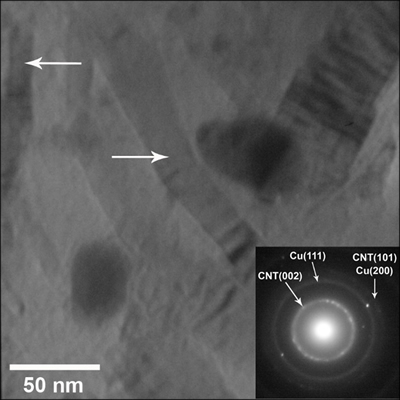
Fig. 8 TEM image of WM3 sample
5 Conclusions
Cu-1%Cr/5%CNT hybrid nano-composite powders were fabricated via wet and dry milling processes at three different levels of milling energy. It was shown that with increasing milling energy in all media, lattice parameters of samples were approximately constant. But, mean crystallite size of dry and wet milled samples showed different trends. In dry milled samples, at high level of milling energy, the mean crystallite size decreased. But, while samples were wet milled, changes of mean crystallite size did not show a definite trend as dry milled samples due to the presence of ethanol and less energy that is attributed to the changing in mean crystallite size, especially in lower levels of milling energy. It was concluded that wet milling at high level of milling energy and dry milling at medium level of milling energy can be considered as efficient ways to reach perfectly embedded CNTs. Also, wet milling process can be considered a better method for dispersing CNTs in the matrix and CNTs would undergo less damage via high energy ball milling process. These results were in agreement with FESEM and TEM results which showed tightly embedded CNTs in the matrix at high level of milling energy. TEM image of WM3 sample confirmed the formation of nano-structured composite. Microhardness results revealed that wet milled powders have higher hardness than dry milled samples. Furthermore, improved dispersion of CNTs and less damage introduced on them during wet milling are more effective than crystallite size reduction.
Acknowledgements
The financial supports of this study by the Iran National Science Foundation (project No: 92013440) and Iran Nanotechnology Initiative Council are gratefully acknowledged. Also, the support of this work by University of Tehran is thanked.
References
[1] CORREIAJ, DAVIES H, SELLARS C. Strengthening in rapidly solidified age hardened Cu-Cr and Cu-Cr-Zr alloys [J]. Acta Materialia, 1997, 45(1): 177-190.
[2] JIN Y, ADACHI K, TAKEUCHI T, SUZUKI H G. Ageing characteristics of Cu-Cr in situ composite, [J]. Materials Science, 1998, 33: 1333-1341.
[3] GAO N, HUTTUNEN-SAARIVITRA E, TIAINEN T, HEMMILA M. Influence of prior deformation on the age hardening of a phosphorus-containing Cu-0.61 wt.% Cr alloy [J]. Materials Science and Engineering A, 2003, 342: 270-278.
[4] SHEIBANI S, HESHMATI-MANESH S, ATAIE A. Influence of Al2O3 nanoparticles on solubility extension of Cr in Cu by mechanical alloying [J]. Acta Materialia, 2010, 58(20): 6828-6834.
[5] SHEIBANI S, HESHMATI-MANESH S, ATAIE A. Structural investigation on nano-crystalline Cu-Cr supersaturated solid solution prepared by mechanical alloying, [J]. Alloys and Compound, 2010, 495: 59-62.
[6] AKBARPOUR M R, SALAHI E, ALIKHANI HESARI F, SIMCHI A, KIM H S. Fabrication, characterization and mechanical properties of hybrid composites of copper using the nanoparticulates of SiC and carbon nanotubes [J]. Materials Science and Engineering A, 2013, 572: 83-90.
[7] CHO S, KIKUCHI K, KAWASAKI A. On the role of amorphous intergranular and interfacial layers in the thermal conductivity of a multi-walled carbon nanotube�Ccopper matrix composite [J]. Acta Materialia, 2012, 60(2): 726-736.
[8] KIM K T, ECKERT J, KIU G, PARK J M, LIM B K, HONG S H. Influence of embedded-carbon nanotubes on the thermal properties of copper matrix nanocomposites processed by molecular-level mixing [J]. Scripta Materialia, 2011, 64(2): 181-184.
[9] CHU K, WU Q, JIA C, LIANG X, NIE J, TIAN W, GAI G, GUO H. Fabrication and effective thermal conductivity of multi-walled carbon nanotubes reinforced Cu matrix composites for heat sink applications [J]. Composites Science and Technology, 2010, 70(2): 298-304.
[10] TSAI P C, JENG Y R. Experimental and numerical investigation into the effect of carbon nanotube buckling on the reinforcement of CNT/Cu composites [J]. Composites Science and Technology, 2013, 79: 28-34.
[11] CHU K, JIA C, LIANG L K, LI W S. Improvement of interface and mechanical properties in carbon nanotube reinforced Cu-Cr matrix composites [J]. Materials and Design, 2013, 45: 407-411.
[12] JIN Y, ZHU L, XUE W, LI W. Fabrication of superaligned carbon nanotubes reinforced copper matrix laminar composite by electrodeposition [J]. Transactions of Nonferrous Metals Society of China, 2015, 25(9): 2994-3001.
[13] KIM B J, OH S Y, YUN H S, KI J H, KIM C J, BEIK S, LIM B S. Synthesis of Cu-CNT nanocomposite powder by ball milling [J]. Nanoscience Nanotechnology, 2009, 9(12): 7393-7397.
[14] YADAV T P, YADAV R M, SINGH D P. Mechanical milling: A top down approach for the synthesis of nanomaterials and nanocomposites [J]. Nanoscience Nanotechnology, 2012, 2(3): 22-48.
[15] ZHANG S, SUI Y, WU B, SONG R, SONG H, JHOU J, CHEN X, LIU J, CAO L. Control of graphitization degree and defects of carbon blacks through ball-milling [J]. Royal Society of Chemistry Advances, 2014, 4(1): 505-509.
[16] TAO Z, JENG H, YU K, YANG Z, WANG Y. Effects of high-energy ball milling on the morphology and the field emission property of multi-walled carbon nanotubes [J]. Materials Letters, 2004, 58(27): 3410-3413.
[17] ZHOU X, DAI Z, BAO J, GOU Y G. Wet milled synthesis of an Sb/MWCNT nanocomposite for improved sodium storage [J]. Materials Chemistry, 2013, 1(44): 13727-13731.
[18] OZKAN A, YEKELER M, CALJAYA M. Kinetics of fine wet grinding of zeolite in a steel ball mill in comparison to dry grinding, International [J]. Mineral Processing, 2009, 90(1): 67-73.
[19] KIM S W, KIM T, KIM Y S, CHOI H S, LIM H J, YANG S J, PARK CH R. Surface modifications for the effective dispersion of carbon nanotubes in solvents and polymers [J]. Carbon, 2012, 50(1): 3-33.
[20] SOTOUDEHNIA M M, PAUL A. Dispersion of carbon nanotubes in iron by wet processing for the preparation of iron�Ccarbon nanotube composites [J]. Powder Technology, 2014, 258: 1-5.
[21] WILLIAMSON G, HALL W. X-ray line broadening from filed aluminium and wolfram [J]. Acta Materialia, 1953, 1(1): 22-31.
[22] MURTY B, RAO M M, RANGANATHAN S. Milling maps and amorphization during mechanical alloying [J]. Acta Materialia, 1995, 43(6): 2443-2450.
[23] BURGIO N, LASONNA A, MAGINI M, MARTELLI S, PADELLA F. Mechanical alloying of the Fe-Zr system. Correlation between input energy and end products [J]. Nuovo Cimento Della Societa Italiana di Fisica, 1991, 13(4): 459-476.
[24] SURYANARAYANA C. Mechanical alloying and milling [J]. Progress in Materials Science, 2001, 46: 1-184.
[25] HODAEI A, ATAIE A, MOSTAFAVI E. Intermediate milling energy optimization to enhance the characteristics of barium hexaferrite magnetic nanoparticles [J]. Journal of Alloys and Compounds, 2015, 640: 162-168.
[26] RAGAB M, SALEM H D. Effect of milling energy on the structural evolution and stability of nanostructured Al-5.7wt.%Ni mechanically alloyed eutectic alloy [J]. Powder Technology, 2012, 222: 108-116.
[27] TORKAN S, ATAIE A, ABDIZADEH H, SHEIBANI S. Effect of milling energy on preparation of nano-structured Fe70Si30 alloys [J]. Powder Technology, 2014, 267: 145-152.
[28] AHMADZADEH M, ATAIE A, MOSTAFAVI E. The effects of mechanical activation energy on the solid-state synthesis process of BiFeO3 [J]. Journal of Alloys and Compounds, 2015, 622: 548-556.
[29] GUZMAN D, ORDONEZ S, SERAFINI D, ROJAS P, BUSTOS O. Effect of the milling energy on the production and thermal stability of amorphous Mg50Ni50 [J]. Journal of Alloys and Compounds, 2009, 471: 435-441.
[30] KARUNATILAKE N, KUHN P, MUTEI L, MUNASINGHE J, SEIBOLD B, SURAJIYONO, THANG P. Dynamics of balls and liquid in a ball mill [C]//Modeling Seminar Summer Term, Kompakseminar Bad Ems 2000. University of Dusseldorf Germany, 2000: 1-36.
��ĥ�����Ի�е�Ͻ�Cu-Cr/CNT��������ϲ����Ʊ���Ӱ��
M. MASROOR, S. SHEIBANI, A. ATAIE
School of Metallurgy and Materials Engineering, College of Engineering,
University of Tehran, P. O. Box 11155-4563, Tehran 13145-1318, Iran
ժ Ҫ��Ϊ���о������ֲ�ͬ�Ľ�������ĥ������̼����(CNTs)��ɢ��Ӱ�죬��3�ֲ�ͬ��ĥ�������£�����ʪĥ��ĥ���Ʊ���Cu-Cr/CNT��������ϲ��ϡ�����X�������似�������˸��ϲ��ϵĽṹ�ݱ���ܱ��Σ�����ɨ�������������������������˸��ϲ��ϵ�����֯����������Ӳ���������������ѧ���ܡ���ƽ�������ߴ緶ΧΪ20~63 nm������ĥ���ʺ���ĥ���йء�CNTs�ķ�ɢ����ĥ�ܳʺ�����ϵ��FESEM�����Ӳ�Ȳ��Խ�����������ĥ����ȣ�ʪĥ����������CNTs�ķ�ɢ���ڸ���ĥ����ʪĥ�����Ʊ����ʻ�������ϲ��ϸ���������CNTs������С������С�ҷ�ɢ�Ϻõ�CNTs�����ڻ�ýϸߵ���Ӳ�ȡ��뾧���ߴ�仯��ȣ�CNTs�ķ�ɢ����Ӳ�ȵ�Ӱ�����
�ؼ��ʣ�̼���ܣ�ͭ�������ϲ��ϣ���е�Ͻ�
(Edited by Xiang-qun LI)
Corresponding author: S. SHEIBANI; Tel: +98-21-61114068; Fax: +98-21-88006076; E-mail: ssheibani@ut.ac.ir
DOI: 10.1016/S1003-6326(16)64239-5
Abstract: Production of Cu-Cr/carbon nanotube (CNT) hybrid nano-composite by wet and dry milling processes at three different levels of milling energy was investigated in order to study the effect of milling energy in two different media on dispersion of CNTs, and preparation of the nano-composite. The structural evolution and solid solution formation were evaluated by X-ray diffraction technique. The microstructure was characterized by scanning electron microscopy and transmission electron microscopy. Also, the mechanical properties were measured by microhardness test. The mean crystallite size was in the range of 20-63 nm depending on milling medium and energy. CNTs dispersion is a function of milling energy. According to FESEM images and microhardness results, it can be concluded that wet milling is more applicable in dispersing CNTs homogeneously in comparison to dry milling. It was also found that wet milling at higher milling energies can be a beneficial method of producing the homogeneous hybrid nano-composite with the least damages introducing on CNTs because of the higher microhardness which can be attributed to better dispersion of less damaged CNTs. Compared with crystallite size changes, CNTs dispersion and damages were considerably more effective on hardness.
