
Article ID: 1003-6326(2005)05-0985-08
Melt metal sheet breaking mechanism
of close-coupled gas atomization
OUYANG Hong-wu(ŷ������), HUANG Bai-yun(�Ʋ���),
CHEN Xin(�� ��), YU Wen-tao(������)
(State Key Laboratory for Powder Metallurgy, Central South University, Changsha 410083, China)
Abstract:
The gas atomization is the process that a liquid mass is disintegrated into a collection of liquid melt droplets by the impact of high velocity gas stream and solidified into metal particles. However, the liquid melt sheet breaking mechanism has not been fully understood. So the experimental research was carried out under the condition of lower melt superheat. The results reveal that there are three approaches about melt metal sheet��s breakage: from the edges of sheets, from inner surface of sheets, and disrupted by other droplets and sheets. The approach of melt sheet breakage is dependent on its thickness. The thicker sheets (above 25��m) are disintegrated mainly by the way of droplet��s departing from edges, and the thinner sheets (below 10��m) are chiefly breaking from the inner surface.
Key words:
atomization; close-coupled nozzle; powder; flow structure CLC number: TF123.1;
Document code: A
1 INTRODUCTION
High pressure gas atomization(HPGA), with high property and efficiency, is the leading method of producing fine spherical metallic powder, and the practice of HPGA in the metal powder manufacturing industry is widespread[1-4]. The close-coupled atomizer, one of the modern gas atomizers, owing to its high fine powder productivity, high solidification rate and lower gas consumption, is superseding traditional atomization processes and becoming the prevalent gas atomization technique gradually[5-10].
In close-coupled atomizer, the molten metal stream is delivered into the atomizing gas via a ceramic melt delivery tube immediately adjacent to the high pressure atomizing gas, subsequently spheroidized, cooled and solidified into fine powder particles. In general, the liquid melt atomization process is composed of several stages: sheet, ligament, ellipsoid and sphere(Fig.1) [11]. The process of sheet-to-ligament is the crucial stage for liquid melt disintegration, and is one of the key points for gas atomization mechanism. Unlike free-fall atomization, the distance between gas jet exit and melt delivery tube is very short in close-coupled nozzle, and there is an inherent atomizing gas recirculation zone where the flow structure is very complicated. The melt stream and the gas flow interact within the recirculation zone, preparing for the following ful atomization.
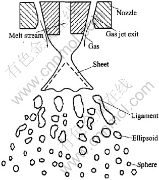
Fig.1 Schematic drawing of close-coupled nozzle and atomization
Presently, with regard to the flow structure feature within the recirculation zone, researchers investigate the flow structure below the melt orifice in the close-coupled nozzle under the condition mainly by the gas dynamics experiment and numerical simulation, so as to gain the distribution features of gas flow on the variables of temperature, pressure and velocity, and to analysze the influence of process parameters (such as gas pressure, stability and nozzle design) thoroughly on the flow structure. However, when the liquid melt is led into the recirculation zone, the incompressible melt and compressible atomizing gas (two-phase flow) interact, especially the mechanism of liquid melt��s sheeting and the sheet breakage have not been studied well. As a result of the general lack of atomization theory and mechanism, the further development and full practice of gas atomization technique is impeded severely[9, 10]. Therefore, the investigation of metal sheet break mechanism in the close-coupled gas atomization was carried out in this paper.
2 EXPERIMENTAL
The gas atomization runned for this study was performed with a close-coupled vacuum atomization crucible made by PSI Ltd. Commercial purity nitrogen was used as the atomizing gas. The atomizing gas source consisting of a bank of twelve nitrogen gas cylinders manifolded to a single two-stage high pressure gas regulator, with a maximum gas pressure of 5MPa. The atomizing gas pressure was set to 3.5MPa. 6kg of copper was selected as atomization metal material. During the experiment, in order to gain metal sheet prior to disintegration, the sheeting and solidification process of the liquid metal was controlled by lowering the melt superheat. A great deal of sheets of copper was obtained, and by this way the metal sheet break mechanism was investigated. The melt temperature was 1445K (the copper��s melting point is 1395K, and superheat is 50K), and the accuracy of temperature measurement was ��2K. The whole atomization process last about 1.5min.
The atomized powder was sieved with 100 mesh sieve (��150��m). Sheets remaining upon the mesh (including some particles) were collected as analysis objects. The sheet surface features were analyzed with KYKY2800.
3 RESULTS AND DISCUSSION
3.1 Results
Generally, in the process of gas atomization, the melt superheat is controlled between 150-250K. On one hand, lowering the viscosity of liquid melt to ensure the melt flowing through the delivery tube steadily; on the other hand, providing the liquid melt with appropriate temperature to ensure the melt not solidifying previously and being fully atomized. Some investigations indicated that the temperature would reduce over 50K when the liquid melt flew out the recirculation zone[12]. While the superheat was lowered in the range of 50K, a portion of melt sheet solidified before full atomization. Thereby, the atomization process can be frozen during the experiment, and nearly 50% of the collection is sheets, which recordes abundant information about the breading process of liquid melt sheet.
3.1.1 Shape feature of metal sheet
The shapes of the collected metal sheet are multiformity, which can be classified approximately into sheet, feather, ligament, acicular, etc, given in Fig.2 and Fig.3, where the proportion of sheet is very near 70%-85% in total; and the feather is more than the ligament by about 10%-20%; the ligament and the acicular are few.
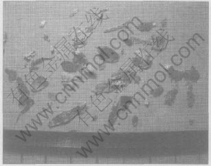
Fig.2 Various shapes of sheets
The thickness of metal sheet is not uniform, generally between 10 and 20��m.The thickest sheet is beyond 40��m, and the thinnest is approximately 3-5��m. Similar to the thickness the sheets vary in size and the average area is about 40mm2; the largest area is around 200mm2, and the smaller area is probably 5-10mm2. The edges of the sheet usually display irregular shape like a zigzag.
3.1.2 Surface characteristic of metal sheet
The metal sheet surfaces show diversification and the profile is also very complicated. Usually the surface of the thicker sheet is with flow traces and smooth relatively, obviously different with the thinner sheet surface which often shows apparent transverse stripes, folds and tiny caves. As a result, the thinner sheet surface is not only awfully rough but also discontinuous and full of bumps. Simultaneously, a great quantity of thinner sheets and tiny particles sticking on the surface were observed. Those thinner and smaller sheets were fused with the thicker and larger sheets, while the tiny particles usually only stick on the surface of sheet, and just a few particles were fused on the sheet surface.
In general, there are a large number of caves on the sheet surface, and these caves often present two types: one is tiny and round caves formed by self-shrinking, including a great part of holes and a few caves, both of which mainly exist in the thinner sheets; the other is comparatively larger caves formed by lacerating of the over thin sheet or by disrupting due to the impact of other particles, consequently the edges is abnormal while a ring lip often exists around these caves.
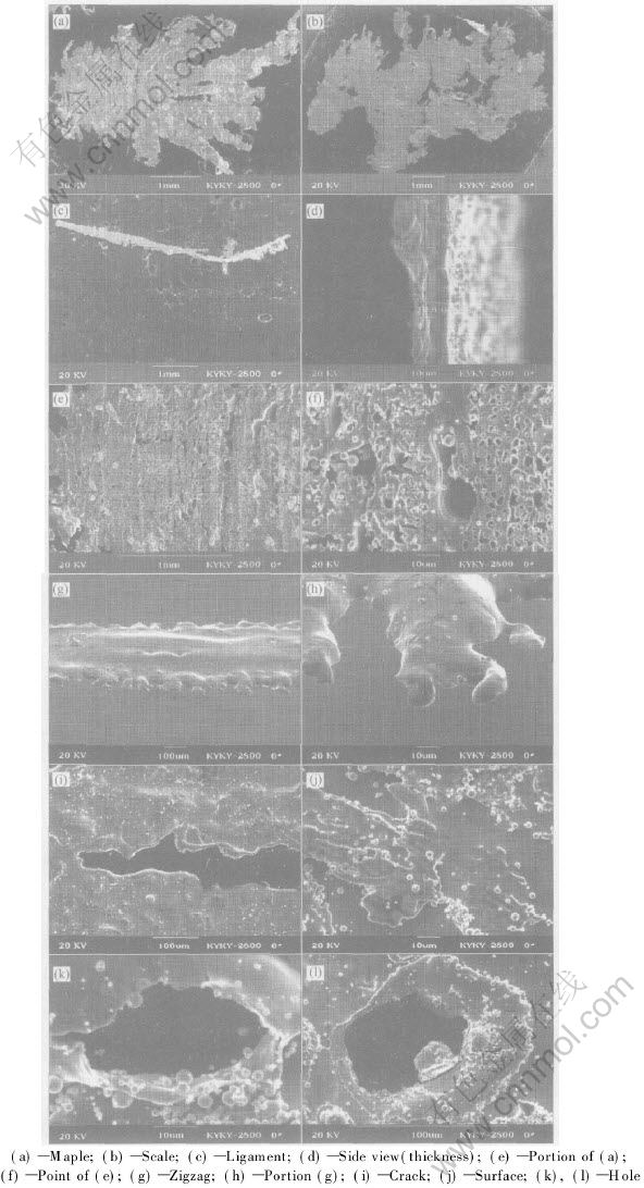
Fig.3 Profile and surface feature of sheets
3.2 Discussion
3.2.1 Gas flow structures feature of close-coupled nozzle
3.2.1.1 Overall feature of gas flow structure
Typically, the high pressure gas jet exiting from the nozzle into a free expansion condition forms a normal shock near its exit. The shock assists the rapidly expanding gas in adjusting to the ambient surrounding pressure. The close-coupled atomizer shows a similar behavior. At 3.5MPa, as the gas expands downstream from the nozzle, an attached oblique shock extends downstream from the feed tube tip, causing the formation of the normal Mach disk. The location of attached oblique shock is closely related to the ��boundary layer�� of gas flow structures.
The close-coupled high-pressure gas atomization flow structures in gas-only condition is shown in Fig.4. There is a recirculation zone like a reverse cone downstream below the nozzle. The top of the cone is the gas stagnation point, where the gas velocity goes to zero while the pressure rising to the maximum. The gas stream enters into the recirculation zone upstream from the stagnation front with a subsonic velocity. At the melt orifice, the recirculating gas turns laterally (radially outward) toward the circumferential edge of the melt from the melt orifice, lengthening the recirculation zone. When reaching the edge, it encounters the sonic boundary, forcing it to turn and flow downstream, and it will be restricted within the recirculation zone, while separated from the supersonic flow field. In light of the atomizing gas flow structure feature, the whole flow field is divided into the recirculation zone and the area outside the recirculation zone. The flow zone of the atomizing gas in the atomization tube is separated from the ambient surrounding by the ��free-boundary��. The basic feature of the flow field structure of the close-coupled nozzle is illustrated in Fig.4[10]. The flow structures will change in case of the variations of operation pressure or other factors.
3.2.1.2 Flow structures feature within recirculation zone
Within the recirculation zone, the gas flow structures feature is obvious, while the details are rather elaborated. In general, the atomizing gas stream in the recirculation zone forms the recirculation eddies which upstream along the central axis and downstream along the cone surface, resulting in the relatively stable recirculation zone and the flow field outside of the recirculation zone. In this case, a very complex turbulent layer is found to separate the recirculation zone and the external flow field.
The turbulent layer is essentially a series of adjoining recirculation eddies that form the lateral perimeter of the recirculation zone within the sonic boundary (see Fig.4) [10]. The atomizing gas exiting from the nozzle enters and exits in the recirculation zone via the stagnation front. The gas velocity magnitude in the turbulent layer is low, however, the mass exchanges across the layer could be significant. In most cases, though, the mass exchanges across the turbulent layer may be equal, i.e. the gas mass entering and exiting across the turbulent layer are comparable. Compared to the gas mass entering the stagnation front and its influence on aspiration pressure, the gas mass exchange across the turbulent layer boundary may not have a significant effect on aspiration pressure.
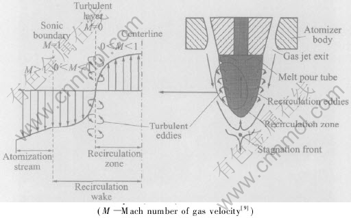
Fig.4 Schematic depiction of close-coupled zozzle atomization flow field gas velocity profile
across turbulent layer (M��0) and sonic boundary (M=1)
Most of the gas does not cross the sonic boundary from the subsonic-side into the supersonic-side of the atomizing free-stream. This is because it is difficult for the abducted subsonic gas to accelerate itself to supersonic speed in order to enter the supersonic free-stream gas on the other side of the sonic boundary. However, the atomizing supersonic free-stream gas can more readily lose its kinetic energy, decelerating to subsonic velocity, in order to cross the sonic boundary and to enter into the subsonic recirculation wake. Some of this decelerated, entrained gas from the supersonic free-stream ends up at the stagnation front, feeding into the recirculation zone via the stagnation front. Simultaneously, at the stagnation front, the remaining balance of the entrained gas exits the wake, accelerating to supersonic velocity to cross again the sonic boundary into the free-stream. Subsequently, this gas addition is pushed upstream along the central axis of the wake until it eventually affects the aspiration pressure at the melt orifice, giving rise to the fluctuation or pulsation of the liquid melt flow rate, thereby influencing the atomization process directly.
The gas-mass flux across the sonic boundary occurs in a direction nearly parallel to this boundary. The velocity gradient across the sonic boundary resembles the shear layer profile of a supersonic flow across a parallel stationary boundary, with the stationary boundary being the turbulent layer. Meanwhile the mass-flux across the turbulent layer occurs essentially in a direction perpendicular to the turbulent layer. This is a result of the numerous toroidal vortices (or turbulent eddies) that give the gas its circular momentum as each vortex rotates. Since the gas behaves as a vortex within the turbulent layer, the net mass-flux across the turbulent layer is negligible.
In gas-only flow conditions, the gas flow field surrounding the nozzle accommodates itself via dynamic gas compression and expansion to modulate the pressure between the high velocity gas and the ambient surroundings. However, introducing liquid metal into the wake during atomization upsets the gas equilibrium. The presence of incompressible liquid in the wake acts against the compressible gas, disturbing and displacing the established gas dynamic flow features. The liquid melt disintegrates into droplets caused by the impacting and extruding of the upstream gas recirculation flow, then enters the turbulent layer. Subsequently some of the liquid melt cross the sonic boundary into the supersonic-side of the atomizing free-stream; the most flow downstream to the stagnation front along the direction parallel to the turbulent layer, cross the sonic boundary into the supersonic gas stream, and atomize into tiny particles after sheeting.
3.2.2 Analysis of metal sheet breakup mechanism
3.2.2.1 Breakage from edge
Being introduced into the recirculation zone, the liquid melt encounters the upstream atomizing gas stream, forcing it turn and flow laterally outward across the cone turbulent layer into the supersonic atomizing gas stream outside the recirculation zone. During crossing the sonic boundary, liquid droplets are extruded into sheets. As the surface area expands promptly, the metal sheet��s surface tension increases similarly. When entering into the supersonic gas flow zone, the melt sheet breaks rapidly by the surface tension and gas impaction due to the sharp decrease of pressure. The process is often termed primary breakup.
At the edge of metal sheet, the surface tension usually reaches the max magnitude. Furthermore, the sheet frontier enters the low pressure zone earlier, therefore, melt sheets disintegrate promptly along the edge into a great number of filaments and small droplets, analogous to the fountain sheet breakup under the atmosphere condition given in Fig.5 that droplets form at the edge of liquid sheet. In the process of gas atomization, these small droplets break into tiny size further as a result of the high velocity gas stream impact. The break mechanism is depicted in Fig.6, comparatively large droplets are disrupted into more tiny size further, and rapidly solidified into fine metal powder particles[13].
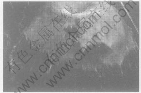
Fig.5 Breakage of water sheet
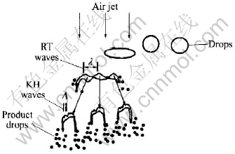
Fig.6 Schematic of break of droplet in high velocity gas stream
Break of metal sheet at the edge shows two different approaches. One is that the metal sheet disintegrates at the edge directly into small melt droplets, as illustrated in Figs.3(g) and (h). A zigzag profile at the edges of the sheet is observed, actually every teeth is the origin of the melt droplets; the other is by the effect of stress concentration, crack formed at the edge extends successively inwards from the stress concentration points, resulting in the melt sheet lacerates vertically, Fig.3(i). Moreover, more tiny melt droplets emerge at the new melt sheet��s edge continuously, accelerating the sheet disintegration.
If the sheet is very thin (less than 15��m), it will break into tiny liquid droplets promptly with interaction attributing to the mutual interaction of the two approaches mentioned above. While the sheet is comparatively thick, it is difficult to initiate breaking. Truly it is firstly lacerated into filament or droplets, then pressed flat into the sheet shape displaying in Fig.3(b) until atomized into fine particles. However, if the sheet is too thick, it��s impossible to beak promptly into tiny liquid droplets or melt sheets, but solidify into sheet shape and deposit into the powder collector, while distinct flow traces existing on the surface. It is thus evident that the melt sheet breakage approach is related to its thickness: when the melt sheet is thicker than 20��m, no caves occur in the surface, showing that disintegration mainly by the droplet��s departing from edges; when thinner than 10��m, a large number of caves emerge in the sheet, suggesting that breaking chiefly originates from the inner surface. For the thickness between 10-20��m, a certain quantities of caves appear in the sheet surface; simultaneously, zigzag is observed at the edge, indicating that under this condition the two approaches effect fairly. Evidently, the thickness of melt sheet is not invariant but alters as the process parameter or the liquid melt property modifies.
The approach of melt sheet breakage is once simplified into a process of melt sheet-to-ligament, which is apparently more complex according to the experimental results. If the melt sheet is thin enough, it is very likely to disintegrate directly into droplets without through the stage of ��ligament��. These droplets in high velocity gas stream is further broken under the mechanism given in Fig.6. It is remarkable that the liquid melt breakage is closely related to the atomizing parameter, so the intensity and strength of breakage may vary with it[14, 15].
3.2.2.2 Breakage from inner surface
Melt sheet may break from the inner surface, which is neglected in the previous investigation. In Figs.3(e) and (f), a series of transverse stripes and many caves forming in the sheet surface are observed clearly. The inner surface is easier to deform owing to its temperature is higher than the edge��s, consequently, during the process of sheeting, the sheet deforms more fiercely, and relatively becomes thinner (comparing to the edge��s). Under the actions of gas pressure and surface tension, a great number of tiny caves turn up, subsequently the metal sheet surface is covered with rich caves. The process of lengthening and pressing continues until the whole sheet is disintegrated and directly into fine particles.
Especially, as a result of the combination between the movements in vertical and transverse direction, the surface of melt sheet extends swift and the surface tension increases correspondingly, hence the melt sheet initiates breakage from the weak points of the inner surface. Generally, melt sheet breaking from the inner will create more tiny droplets. These droplets in the high velocity gas stream may break further or solidify into particles immediately. This process is directly related to the metal sheet temperature and size: the smaller the diameter is, the faster the solidification will be. If the temperature is close to the melting point, the droplets may be unable to be finer due to rapid cooling. Only with temperature high enough and comparatively larger diameter, the droplet would undergo further disintegration. Obviously, it has a close relationship with the gas kinetic energy. When the kinetic energy of gas and temperature of sheet are high enough, droplets can been further disintegrated. Analyzed from the atomizing gas kinetic energy, the higher velocity the atomizing gas possess, the more benifit for the further disintegrating of the droplet. However, remarkably because of the gas��s rapid expanding, the temperature decreases substantially, which is detrimental to the atomization. Adopting hot gas atomization into the above process, the atomization can be notably improved, which is one of the important reasons that hot gas atomization is effective to produce finer powder[16].
3.2.2.3 Interference of other droplets
In the process of melt sheet breakage, interference of other sheets or droplets is also essential factor causing the melt sheet to disrupt acceleratedly. When the melt sheets are lengthened and pressed then broken into finer droplets, with extending the area and volume of sheet, the impact probability among the sheets or between the sheets and droplets rises, meanwhile the mutual interaction is unavoidable. From Fig.3(j), it can be seen that many smaller area sheets and very tiny droplets are sticking in the larger melt sheets. Simultaneously, larger holes commonly occur in the melt sheets, seen in Figs.3(k) and (l). The disorderliness of the melt sheet breakage rises up, attributing to the interference of other droplets and melt sheets. For this reason, it may accelerate the melt sheet breakage, but the probability of satellite balls producing will rise, which is harmful to the powder quality. So further investigation is still to be carried out.
3.2.3 Influences of process parameters on melt sheet breakage
Typically, the principal performance of an atomization system is due to the operational conditions of the atomizer nozzle. Once the nozzle is designed it is generally considered an invariant and ��fine tuning�� of the atomization process is achieved by optimizing the operational parameters of gas pressure, gas/melt flow rate, and melt superheat[16-18]. Although engineering studies of these parameters are numerous in the literature, in fact, it��s difficult to coordinate the mass factors and the relationship between the mass median diameter and process parameters is still elusive. At present, the best-known and most commonly quoted correlation for the gas atomized metal droplet diameter (or mass median diameter) proposed by Lubanska[19]. The mass median diameter(MMD, DMM) can be represented by the following equation:
![]()
where d0 is the melt delivery tube orifice diameter; kD is a constant whose value was found to be between 40 and 50 for various metals and inorganics, [AKm��D]L and [AKm��D]G are the mass flow rates of atomization gas and liquid metal, respectively; vG and vL are the kinematic viscosities of the gas and the liquid, respectively; and We is the dimensionless Weber number, ![]() ; �� and �� represent the density and surface tension of the liquid, respectively, and UG is the gas velocity at impact with the liquid.
; �� and �� represent the density and surface tension of the liquid, respectively, and UG is the gas velocity at impact with the liquid.
According to Eqn.(1), DMM is a strong function of the gas velocity and the mass flow rate ratio ([AKm��D]L/[AKm��D]G) commonly referred as the ��gas-to-metal ratio��(GMR) in melt atomization. The gas velocity depends on the gas pressure, gas type and temperature. Increasing the gas pressure and temperature will increase the gas kinetic energy, thus increasing temperature is very effective to improve the atomization efficiency and decrease the DMM, where decreasing the proportion of particles with large diameter is the most effective method to decrease the DMM[10-22].
Intuitively, one would assume that, at a fixed d0, the GMR is related to the operating pressure of the atomizer gas supply, such that the high and low GMRs are directly associated with the high and low atomization gas pressures, respectively. This, however, is not always true in a close-coupled atomization process. It has been recently shown that the GMR can change dramatically (by 37.2%) at two atomization pressures that differ by less than 1.5%. It is thus evident that in the close-coupled gas atomization the influence of operational parameters on the atomization process and results is extremely complicated, and unable to be regarded in the same frame of mind.
Based on the discussion above, gaining thinner melt sheet is crucial to the high efficiency breakage. If thinner melt sheet can not be produced stably, the larger and thicker sheets will not be break into fine and uniform particles promptly. Furthermore, the probability of producing large diameter particles may rise up, and the yield of fine powder will decrease obviously. The process parameters in the close-coupled gas atomization have strong influence on the atomizing gas flow structures, accordingly varying the melt sheet break mechanism greatly, consequently affecting the melt sheet breakage.
4 CONSLUCIONS
1) In close-coupled gas atomization, the process of metal sheet breakage is complex and diversified. Generally, there are three approaches to liquid droplet��s breakage: breaking from the edges; breaking from the inner surface; and being disrupted due to the interference of other droplets and sheets.
2) The melt sheet breakage approach is related to its thickness: when the melt sheet is thicker than 20��m, no caves occur on the surface, showing that disintegration mainly by the droplet��s departing from edges; when the thickness is below 10��m, a large number of caves emerge in the sheet, stating that breaking chiefly originates from the inner surface; when the thickness is between 10 and 20��m, a certain quantities of caves appear on the sheet surface. Simultaneously, zigzags are observed at the edge, indicating that under this condition the two approaches effect fairly.
3) In the close-coupled gas atomization the interaction between the atomizing gas and the liquid melt is so complicated that the selection of process parameters is determined from the experience. Under the normal operational conditions, the prerequisite of enhancing the melt sheet breakage and producing uniform fine powder is gaining comparatively thinner (about 10��m) and uniform metal sheets.
REFERENCES
[1]Dowson A G. Atomization dominates powder production [J]. MPR, 1999, 54(1): 15-17.
[2]Schulz G. Some applications of ultrafine, gas atomized metal powder beyond classical powder metallurgy [A]. Kosuge K, Nagai H. Proc of 2000 Powder Metallurgy World Congress [C]. Japan: The Japan Party of Powder and Powder Metallurgy, 2000. 475-478.
[3]Miller S A. Close-coupled gas atomization of metal alloy [A]. Proceedings��PM��86 [C]. 1986. 29-32.
[4]Alan Laulgy. Atomization: The Production of Metal Powder. Metal Powder Industries Federation, Princeton, NJ, 1992:76
[5]Mates S P, Settles G S. High-speed imaging of liquid atomization by two different close-coupled nozzles [A]. Cadle T M, Narasimhan K S. Advances in Powder Metallurgy & Particulate Materials-1996 [C]. Princeton, NJ: MPIF, 1996. 67-80.
[6]Liu H, Robert F. Effect of atomizer geometry and configuration on gas flow field in gas atomization [A]. Cadle T M, Narasimhan K S. Advances in Powder Metallurgy & Particulate Materials-1997(part 1) [C]. Princeton, NF: MPIF, 1997. 5-10.
[7]Espina P I, Piomelli U. Numerical simulation of the gas flow in gas-metal atomizers [A]. Cadle T M, Narasimhan K S. Proceedings of FEDSM 98 [C]. Princeton, NF: MPIF, 1998. 1-11.
[8]Dunkley J. Water bench testing boots gas atomizing [J]. MPR, 1999, 54(3): 26-29.
[9]Jason Ting, Anderson I E. A computational fluid dynamics (CFD) investigation of the wake closure phenomenon [J]. Materials Science and Engineering A, 2004, 379: 264-276.
[10]Jason Ting, Peretti M W, Eisen W B. The effect of wake-closure phenomenon on gas atomization performance [J]. Materials Science and Engineering A, 2002, 326: 110-121.(in Chinese)
[11]HUANG Pei-yun. The Principle of Powder Metallurgy [M]. Beijing: Metallurgical Industry Press, 1988. 99.
[12]LIU Yun-zhong, CHEN Zhe-hua, WANG Jian N. Numerical simulation of the thermal history of droplets during multi-stage atomization [J]. Science and Technology of Advanced Material, 2001, 2: 177-180.
[13]Lee C H, Reitz R D. An experimental study of the e.ect of gas density on the distortion and breakup mechanism of drops in high speed gas stream [J]. International Journal of Multiphase Flow, 2000, 26: 229-244.
[14]LI Qing-quan. The principle of powder production by the closed-coupled gas atomization [J]. Powder Metallurgy Industry, 1999, 9(5): 3-17.
[15]Sheikhaliev S M, Beryukhov A V, Dunkley J J. Metal droplet��s deformation and break-up by a gas stream [A]. Euro PM2004 [C]. 2004. 1-6.
[16]Strauss J T. Hotter gas increases atomization efficiency [J]. MPR. 1999, 54(11): 24.
[17]Strauss J T, Miller S A. Effect of gas properties in powder yield produced by close-coupled gas atomization [A]. Advances in Powder Metallurgy & Particulate Technology-1997(part1) [C]. Princeton, NJ: MPIF,1997(5): 45-52.
[18]Strauss T J. Close-coupled gas atomization using elevated temperature gas [A]. Advances in PM and P Tech [C]. 1999. 23-34.
[19]Murray I F, Heister S D. On a droplet��s response to acoustic excitation [J]. International Journal of Multiphase Flow 1999, 25: 531-550.
[20]Strauss J T, Scorey C R, McKernan J E, et al. Polymer atomization of iron aluminide [J]. Materials Science and Engineering A, 1998, 258: 291-297.
[21]Anderson I E, Terpstra R L. Progress toward gas atomization processing with increased uniformity and control [J]. Materials Science and Engineering A, 2002, 326: 101-109.
[22]Henein H. Single fluid atomization through the application of impulses to a melt [J]. Materials Science and Engineering A, 2002, 326: 92-100.
Received date: 2004-12-26; Accepted date: 2005-05-25
Correspondence: OUYANG Hong-wu, Professor, PhD; Tel: +86-13974870566
