
Trans. Nonferrous Met. Soc. China 24(2014) 3611-3620
Forming defects in aluminum alloy hot stamping of side-door impact beam
Jing ZHOU1, Bao-yu WANG1, Jian-guo LIN1,2, Lei FU1, Wen-yu MA1
1. School of Mechanical Engineering, University of Science and Technology Beijing, Beijing 100083, China;
2. Department of Mechanical Engineering, Imperial College, London SW7 2AZ, UK
Received 6 December 2013; accepted 23 June 2014
Abstract:
The forming defects, including thinning, rupture, wrinkling and springback, usually arising in producing a side-door impact beam, were investigated by trial and numerical simulation. A temperature-related constitutive model specific to the temperature range from 350 ��C to 500 ��C was established and used for the numerical simulation. The trial and numerical simulation were conducted to clarify the quantitative characteristics of forming defects and to analyze the effects of process parameters on the forming defects. Results show that the rupture situation is ameliorated and the springback is eliminated in the aluminum alloy hot stamping. The wrinkling severity decreases with increasing blank holder force (BHF), but the BHF greater than 15 kN causes the rupture at the deepest drawing position of workpiece. The forming defects are avoided with lubricant in the feasible ranges of process parameters: the BHF of 3 to 5 kN and the stamping speed of 50 to 200 mm/s.
Key words:
aluminum alloy; hot stamping; forming defects; numerical simulation; blank holder force;
1 Introduction
In the upcoming years, one of the most important challenges to automotive industry is to meet the demand of reducing fuel consumption with a concurrent improvement for the safety performance of automobile. This requirement is satisfied mainly by using light-mass materials such as advanced high-strength steels, aluminum alloys, magnesium alloys and composites to produce auto-body components. Some novel or improved manufacturing processes are introduced for forming these new-fashioned materials.
In order to overcome the major problems in producing aluminum alloy panel components such as springback, poor formability and microstructure variation, a novel process HFQ was proposed by LIN et al [1-3] in recent years. Solution heat treatment (SHT), hot forming, cold die quenching and artificial aging are successively connected in this process. There are three main steps in this process as schematically shown in Fig. 1.
1) SHT: A sheet blank is soaked at an elevated temperature for a sufficient period, which fully dissolves alloying elements into solid aluminum and gives one single phase.
2) Hot forming and die quenching: The hot blank is transferred to a cold die set where it is quickly formed and held within the dies until quenched to room temperature, which leaves the alloying elements in the unstable solid solution known as ��super saturated solid solution��.
3) Artificial aging: Age-hardening is the final stage to improve the properties of heat treatable aluminum alloys. The alloying elements come out of the solid solution to form strengthening particles with appropriate aging time and temperature.
Since HFQ process is proposed, a few researchers have paid attention on it and used finite element (FE) method to investigate the forming defects and the effects of process parameters. Finite element method has become a powerful tool in predicting and preventing the undesirable forming defects of material forming processes. Only few works focusing on the numerical simulation of aluminum alloy hot stamping have been reported in the literatures [4-6] as yet, whereas some investigations focusing on the numerical simulation of boron steel hot stamping have been published. XING et al [7] established a material model of boron steel, and used the finite element code ABAQUS to carry out the numerical simulation of boron steel hot stamping process for a bending part. SHAPIRO [8] applied the finite element code LS-DYNA in solving the Numisheet 2008 benchmark problem that is relevant to the hot stamping of a B-pillar component. MOHAMED et al [2] established a set of damage-coupled viscoplastic constitutive equations for predicting the material damage in hot sheet forming and implemented the equations in the ABAQUS software through the user-defined subroutine VUMAT for the numerical simulation of aluminum alloy hot stamping.
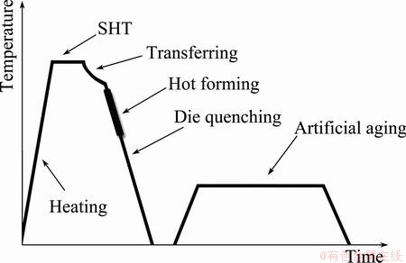
Fig. 1 Schematic diagram showing temperature history of HFQ process
The warm forming of aluminum alloy was also proposed and developed in the last few decades, and recent results [9-11] show that the formability of aluminum alloy is increased in an elevated temperature range. In addition, the nature of some aluminum alloys under the warm forming condition was investigated and reported [12-14]. The warm forming can improve the formability significantly, but the benefits from raising the temperature of tools and blank would be limited compared with the additional complexity of heating the tools and blank. Superplastic forming has also been used to form aluminum closure panels for recent decades [15]. The primary advantage of superplastic forming is to manufacture large and complex shapes from materials with low formability. However, the main obstacle for the further application of superplastic forming is low productivity due to the relatively slow cycle time [16]. In addition, most of the materials employed in superplastic forming demand a special preprocessing to get a fine- or ultrafine-grained microstructure [17]. The material formed at high temperature in HFQ process makes it possible to achieve a higher level of ductility compared to that at moderate temperature in warming forming, which implies that more complex components can be formed by using HFQ process. The springback of components is eliminated because stress release takes place when the material is held within the die set, which improves the geometrical accuracy of components.
HFQ process is applied to producing a side-door impact beam of car in this work. The forming defects arising in the actual production are investigated by using FE analyses and stamping trials. The constitutive model of AA6111 under HFQ condition, the geometric model and thermal aspects of numerical simulation are presented. The characteristics of forming defects are analyzed and discussed.
2 Numerical simulation of aluminum alloy hot stamping
2.1 Material constitutive model
Flow stress represents the size of the yield function during deformation, and is usually influenced by not only strain but also strain rate and temperature. The behavior of the metals undergoing plastic deformation at high temperatures and different strain rates should be modeled according to the physical behavior of the material [18]. An adapted constitutive equation for describing the material behavior under the hot stamping condition, depending on temperature and strain rate, is selected to apply in the numerical simulations.
ABEDRABBO et al [19] applied an equation of the flow stress including the strain rate sensitivity to performing the coupled thermo-mechanical finite element analyses. Temperature effect is considered and included in this flow equation described by Eq. (1), which is used in the following simulations.
 (1)
(1)
where K(T) represents strength coefficient, n(T) is the temperature dependent strain hardening coefficient and m(T) is the temperature dependent strain rate sensitivity coefficient.  denotes the effective plastic strain and
  denotes the effective strain rate.
  is a constant representing the elastic strain to yield and
  is a strain rate normalization factor whose value depends on the time units used in FE simulation. These material constants and coefficients are estimated according to the stress-strain curves obtained from the hot compression test on a Gleeble-1500 thermal-mechanical testing system.
The symbols in Fig. 2(a) show the hot compression results for AA6111 aluminium alloy deformed at four different strain rates (0.01, 0.1, 1 and 10 s-1) and deformation temperature of 400 ��C. The flow stress increases as the strain rate goes up, which indicates a noticeable viscoplastic nature of materials at high temperature. The symbols in Fig. 2(b) show the hot compression results for AA6111 aluminium alloy deformed at four different deformation temperatures (350, 400, 450 and 500 ��C) and a strain rate of 1 s-1. The flow stress decreases with the increasing temperature.
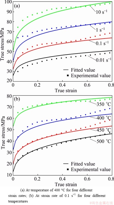
Fig. 2 Comparison between fitted (solid curves) and experimental (symbols) stress-strain relationships of AA6111 alunnium alloy
Figure 3 presents the relationships between the material coefficients (K, n and m) and the deformation temperature (T), and their temperature-dependent expressions that are specific to the temperature range from 350 ��C to 500 ��C. In Eq. (1), the initial elastic strain to yield equals 0.05, and the strain rate normalization factor is 0.01 s-1. Once the material constants and coefficients are determined, the flow stress under a designated condition can be predicted. The solid curves in Fig. 2 show that the flow stress predicted by Eq. (1) is close to the experimental data under the hot stamping conditions. The hardening curves calculated by Eq. (1) at the temperatures and strain rates covering the range likely to be encountered during the trial are used in the numerical simulations.

Fig. 3 Relationships between material coefficients and deformation temperature T by polynomial fit
2.2 Geometric model
Figure 4(a) shows the three-dimensional geometric model and actual workpiece of the side-door impact beam. A quarter FE model is established because the dies and blank are axial symmetric, as shown in Fig. 4(b). The material model of blank adopts an elastic-plastic thermal material model. The blank is of 1100 mm in length, 200 mm in width and 2 mm in thickness, and is meshed by the quadrilateral thermo-mechanical B-T shell elements. Die set is regarded as rigid body due to its insignificant elastic deformation
Figure 4(b) indicates the relative location relation between dies and blank, and an inverse installing assemble is applied to stamping trial. The upper die with stamping speed presses the blank to lower die. The lower die is fixed, and the blank holder and upper die are constrained in three rotational freedoms and in two translational freedoms (the x and y positions). The blank holder force is applied to the blank holder along the negative z axis. The actual speed of press is applied on the upper die without any mass scaling to improve the calculating speed.

Fig. 4 CAD model and actual workpiece of side-door impact beam (a) and FE model of aluminum alloy hot stamping simulation of side-door impact beam (b)
2.3 Heat loss in transferring blank
Before the forming stage, the blank is heated to over 500 ��C for a period and then is taken out of the furnace. The hot blank inevitably loses heat to environment by convention and radiation during transferring it from the furnace to the press. The heat loss during the blank transferring stage influences not only the formability of sheets, but also the mechanical properties of final stamping parts [20]. It is necessary to reckon the temperature variation of the blank during the transferring stage.
Irrespective of the heat conduction between the blank and transferring fixture, the heat loss in the transferring stage is regarded as ��natural convection��. If a process is associated with heat radiation, the total heat transfer of the process by time and surface unit is given by
 (2)
(2)
where Tb is the blank temperature and Ta is the air temperature or the environment temperature. ��c means the heat transfer coefficient of heat convection and ��r is the heat transfer coefficient of heat radiation.
Based on engineering heat transfer knowledge [8], the convective heat transfer coefficient for the horizontal plane plate can be calculated by using the standard empirical equations as presented in Eqs. (3-6).
 (3)
(3)
 (4)
(4)
 (5)
(5)
 (6)
(6)
where Nu, Gr and Pr represent the Nusselt, Grashof and Prandtl numbers, respectively; L is the length scale that equals the plate area divided by the plate perimeter; k is thermal conductivity; �� is the air density; g is gravity acceleration; �� is cubic expansion coefficient; ��t is the difference in temperature between the blank and air; �� is dynamic viscosity; cp is isobaric specific heat.
The properties of air used in calculating Grashof number and Prandtl number are evaluated at the film temperature that is the average temperature between the blank and air, and the air temperature is assumed to be 25 ��C and the blank temperature is assumed to be 540 ��C. The length scale L equals 0.3385 m, the thermal conductivity k equals 0.0447 W/(m��K), the Prandtl number Pr equals 0.676, the air density �� equals 0.6349 kg/m3, the dynamic viscosity �� equals 28.68��10-6 N��s/m2, and the cubic expansion coefficient �� equals 1.8��10-6 ��C-1.
In Eq. (4), the constants C=0.14 and n=1/3 for top surface, and C=0.27 and n=1/4 for bottom surface. The convective heat transfer coefficients for two sides are ��c,top=9.04 W/(m2��K) and ��c,bottom=3.71 W/(m2��K), calculated by Eqs. (3)-(6).
According to Stefan-Boltzmann��s law, the radiating heat transfer coefficient can be calculated by Eq. (7).
 (7)
(7)
where �� is Stefan-Boltzmann��s constant, and �� representing the emissivity of the aluminum alloy wrought sheet equals 0.19. The radiating heat transfer coefficient is ��r=8.97 W/(m2��K).
Assuming that the heat transfer coefficients and the specific heat are constant with temperature variation, we can perform an energy balance on the blank by equating its change in internal energy to the heat loss by convection and radiation from both sides of the blank, as shown by Eq. (8).
 (8)
(8)
where �� is the blank density, cp is the heat capacity of the blank, V is the blank volume and A is the one-side area of the blank. ��T is the temperature fall of the blank, and t is the time of the blank transferring stage. If the time for transferring the blank is approximately 10 s, the blank temperature will decrease about 33 ��C.
2.4 Thermal contact and friction setting
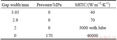
The lower surface of blank begins to cool when the blank (about 500 ��C) contacts with the blank holder and lower die (25 ��C). FOSTER et al [21] investigated the surface heat transfer between the tools and blank of HFQ process. Based on their results, the mild steel to aluminum alloy surface heat transfer with lube is much greater than the heat convection and radiation of blank that could be negligible in the numerical simulations. PAM-STAMPTM, a FE code, has capability to model the surface heat transfer coefficient (SHTC) as a function of the interfacial contact pressure and the gap between the tools and blank. The die temperature is set as the room temperature 25 ��C in numerical simulation. Table 1 presents the variation of SHTC with different pressures and gaps.
Coulomb friction is considered in the contact between the blank and dies, which is usually used in the numerical simulation of stamping process. The friction coefficient is set as 0.12 for the normal metal-to-metal sliding with lube.
Table 1 SHTC between aluminum alloy sheet and mild steel die
2.5 Simulation results
The process parameters of finite element model are defined as: the blank temperature is 500 ��C; the tools�� temperature is 25 ��C; the velocity of upper die is 100 mm/s; and the blank hold force equals 10 kN. The numerical simulations were carried out.
The contours of side-door impact beam are shown in Fig. 5. The maximum thickness is 2.38 mm (thickening 19%) and the minimum thickness is 1.56 mm (thinning 22%), as shown in Fig. 5(a). The relatively severe thinning occurs on the inside wall of side-door impact beam. Figure 5(b) indicates that the maximum of effective plastic strain equals 0.33 which is less than the material limit strain. The temperature distribution at the last moment of forming stage is shown in Fig. 5(c). Because the blank touches the blank holder first and then the lower die, the temperature of blank within the cavity of the dies is far higher than the part clamped between the blank holder and upper die. Moreover, the energy transformation of plastic deformation causes the increase of blank temperature.
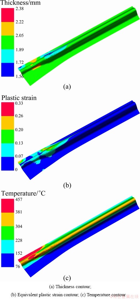
Fig. 5 Result contours of FE simulation
3 Hot stamping trial
3.1 Trial apparatus
The AA6111 aluminium alloy cold-rolled sheet of initial thickness 2 mm is chosen in the stamping trials. A 500 t hydraulic press that has the function of holding pressure in the quenching stage was used to carry out the trials. A tool set was designed to tentatively produce the side-door impact beam and was installed at the workbench of press as shown in Fig. 6. The tool set consists of four main parts: upper die, lower die, blank holder and pin-lift. The blank surface is smeared with the heat resisting graphitic lubricant in the stamping trials. Two kinds of stamping trials are implemented: 1) the contrast between the cold stamping and hot stamping, and 2) the investigation of forming defects under different BHFs.
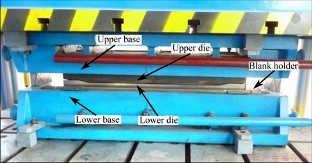
Fig. 6 Tool set for stamping trials installed on press
In the holding stage, the blank holder is pushed up by the pin-lift, and the heat blank is placed on the blank holder. The heat blank clamped between the upper die and blank holder is pressed to the lower die in the forming stage, and then is cooled in the die set to obtain the desired mechanical properties. The blank holder force is controlled by the pressure of hydraulic pin-lift.
3.2 Trial results
Two types of forming defects are observed in the stamping trials: 1) the wrinkles at the flange of side-door impact beam and 2) the local thinning and even the rupture emanating from the deepest drawing side-wall of workpiece. Figures 7(a), (b) and (c) show the hot stamping workpiece with the stamping speed of about 100 mm/s and the BHF of 1, 2.5 and 15 kN, respectively. Figure 7(d) shows the cold stamping workpiece with the stamping speed of about 100 mm/s and the BHF of 2.5 kN.
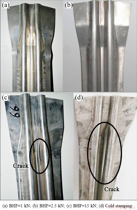
Fig. 7 Side-door impact beam formed under different conditions
The crack is found at the deepest drawing side-wall of both the cold stamping and hot stamping workpiece. The rupture of cold stamping workpiece is more serious than that of hot stamping workpiece under the same forming condition, which indicates that the formability of AA6111 aluminium alloy at room temperature is poorer than that at the temperature of hot stamping. The BHF is one of the critical factors influencing the forming quality regardless of the forming temperature.
4 Forming defects in aluminum alloy hot stamping
The instability phenomena of material and shape such as necking and buckling are principal issues that must be addressed in the part design. The tearing failure resulting from the material necking and the wrinkling due to the sheet buckling hinders the subsequent manufacturing process. Except tearing and wrinkling, springback that is an important factor to dimension accuracy is also often observed in hot stamping. Some representative cross-sections are designated to analyze the thickness variation and the springback as shown in Fig. 8(a), and Fig. 8(b) shows the springback indices ��1, ��2 and d on section D-D��to quantify the springback level.
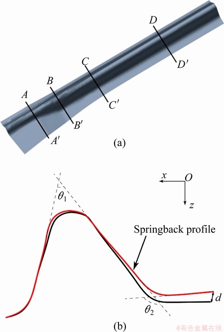
Fig. 8 Location of cross-sections to analyze thickness and springback (a) and definition of springback indices on section D-D�� (b)
4.1 Thickness variation and rupture
Thickness is an important index to evaluate the forming quality, and the excessive thinning or thickening causes some problems in the subsequent processes. Investigating the thickness distribution and variation is, therefore, important to improve the forming quality. The thickness variation is expressed as the relative thickness percentage, because the value of thickness variation is quite small. It is found that the thinning more than 20% will cause the rupture by comparing the results obtained from the trial and numerical simulation. The thinning of 20% is set as a simple judgment for rupture in following discussion.
Figure 9 shows the quantitative comparison of
thickness distribution between the trial results and simulation results at sections A-A��, B-B�� and C-C��. The corresponding process condition is of 2.5 kN in BHF and of 100 mm/s in stamping speed. The figure indicates that the finite element analysis result is in close coincidence with the measured thickness. Based on the practical experience in hot stamping, the clearance of the tools is usually designed as 10%-20% thicker than the blank to prevent the material from getting stuck. Most of section A-A�� thickens as shown in Fig. 9(a), which is due to the clearance of the tools and the lateral compressive deformation. The trends of thickness variation on section B-B�� (Fig. 9(b)) and C-C�� (Fig. 9(c)) are similar. The thinning on section B-B' is a little severer than that on the section C-C'. The maximum thinning place that is of 1.76 mm in thickness appears on the inside wall of section B-B', whereas the maximum thickness equals 2.07 mm locating at the inside wall of section A-A'.
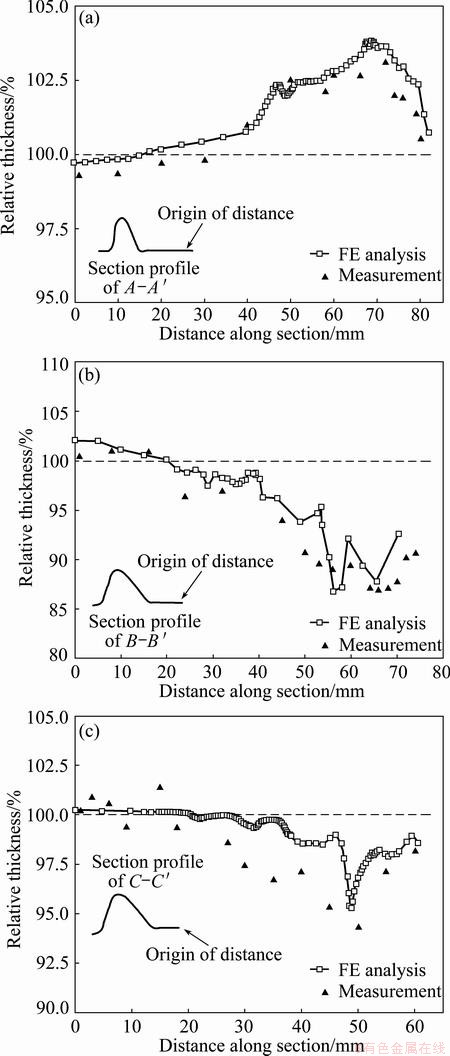
Fig. 9 Comparison of thickness distribution between numerical simulation and trial on section A-A�� (a), section B-B�� (b), section C-C�� (c)
The thickness variations of section B-B�� under different BHFs and the constant stamping speed of 100 mm/s are compared, as shown in Fig. 10. The minimum thickness of section B-B�� decreases with the increasing BHF and is almost invariant for the BHFs of 2.5 kN and 5 kN. The portion of blank clamped by the blank holder and upper die is not deformed, and the corresponding thickness is nearly unchanged from the initial blank thickness. The rupture might occur on section B-B�� due to the acute thinning, once the BHF is close to 20 kN.
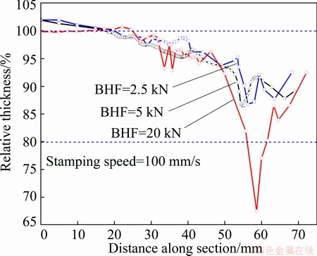
Fig. 10 Thickness distribution on section B-B�� with different BHFs
Figure 11(a) demonstrates that the thinning changes gently at the BHF of 2 to 5 kN when friction coefficient is set as 0.12, but the minimum thickness declines acutely as the BHF increases when friction coefficient is set as 0.20. It is seen from Fig. 11(b) that the minimum thickness decreases as BHF increases, and the trends of these curves at different stamping speeds are similar. The slopes of three curves are small when the BHF is less than 5 kN, but the curves steepen when the BHF is greater than 10 kN. The minimum thickness becomes unaccepted as the stamping speed increases, but a faster stamping speed is conducive to the die quenching which can freeze the alloying elements that mass toughening particles during the next aging stage. The suitable stamping speed of 100 mm/s is selected to reach a compromise between the opposite effects.
4.2 Wrinkling
Wrinkling is not generally desirable in stamping or other forming processes. Because the wrinkles on the mating surfaces not only influence the reliability of down-stream assembling and the part functions, but also damage or even destroy the tools. In addition, the wrinkles occurring in the outer skin panels are also unacceptable under the condition that the part appearance is critical.
From the viewpoint of mechanics analysis, wrinkling is a phenomenon of compressive instability in the presence of excessive planar compression. There are two common kinds of wrinkling in sheet forming: one is the flange wrinkling which usually initiates from the blank-holder zone, and the other is the side-wall wrinkling. We will concentrate on the flange wrinkling and validate the relation between the BHF and wrinkling.

Fig. 11 Minimum thickness obtained from FE analysis versus BHF under different friction coefficients (a) and different stamping speeds (b)

Fig. 12 Flanges of workpieces deformed under different BHFs
It is well known that increasing the BHF could suppress the flange wrinkling and might easily induce an acute rupture. With regard to the side-door impact beam, the relation between the flange wrinkling and BHF is presented in Fig. 12. The wrinkles are obvious and its height is about 6 mm, which is triple of the initial blank thickness when the BHF is zero. The height of wrinkles decreases to approximately 2 mm when the BHF increases to 1 kN. The wrinkles disappear when the BHF is close to 5 kN. The undue BHF of 20 kN causes a rupture emerging on the side-wall of the deepest drawing position, despite no wrinkling on the flange.
4.3 Springback
Springback is a phenomenon that takes place during the last stage of sheet forming process caused by the release of internal residual stresses which are non-uniformly distributed over the workpiece. Based on the researches carried out in the last decade, we are aware of that many technical factors and physical and metallurgical parameters have important influences on springback [22]. It is generally considered that springback is as a result that the deformation zones have two layers of different stress states: bending and stretching which simultaneously produce a compression and a tension in the first layer and two tensions in the second layer.
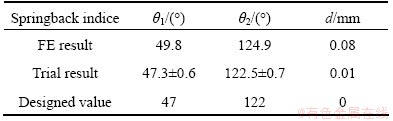
Two angles and a distance on section D-D��, as shown in Fig. 8(b), are selected to evaluate and measure the amount of springback. A transversal slice near the section D-D�� is cut from the stamping part by electric-discharge cutting to measure the actual springback indices: ��1, ��2 and d. In Table 2, the springback indices measured from the actual parts and obtained from the FE analyses are compared with the design values under the condition with the BHF of 5 kN and the stamping speed of 100 mm/s. The trial results are close to the design values but a small difference between the design values and FE results is found. The accuracy of numerical simulation in predicting springback must be improved if we want to use the FE analysis to investigate the springback problem in the hot stamping.
Table 2 Measured, FE and designed springback indices
The measured deviations of springback angles from the design values versus the different BHFs are shown in Fig. 13. The BHF has no remarkable effect on the deviations of the springback angles, which implies that the springback in the aluminum alloy hot stamping is suppressed by die quenching.
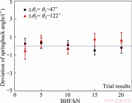
Fig. 13 Influence of BHF on springback (deviations of angles) based on trial results
5 Conclusions
1) The formability of AA6111 aluminium alloy at high temperature is more excellent than that at room temperature, and the forming quality in HFQ process is much better than that in the traditional cold stamping.
2) The material constitutive model and the FE model presented could be used to predict the forming defects arising in the actual HFQ process. This investigation provides a reference model to the automobile manufacturers by establishing the FE model of aluminum alloy hot stamping process.
3) The BHF that is the most significant factor affects the thinning, rupture and wrinkling, but it has little influence on the springback in HFQ process. The wrinkling height decreases as the BHF increases, but the BHF greater than 15 kN induces a crack on the deepest drawing side-wall of workpiece.
4) By analyzing the results of numerical simulation and trial, the process condition that the BHF takes in the range of 3 to 5 kN at the stamping speed of 50 to 200 mm/s with lubricant could avert any forming defects in producing the side-door impact beam.
References
[1] MOHAMED M S, FOSTER A D, LIN J. Solution heat treatment in HFQ process [J]. Steel Research International. Cracow, Poland, 2008, 79(11): 160-167.
[2] MOHAMED M S, FOSTER A D, LIN J, BALINT D S, DEAN T A. Investigation of deformation and failure features of AA6082: Experimentation and modelling [J]. International Journal of Machine Tools & Manufacture, 2012, 53(1): 27-38.
[3] LIN J, DEAN T A, GARRETT R P, FOSTER A D. Process for forming aluminium alloy sheet components: UK, WO2008059242 [P]. 2008-09-19.
[4] ZHOU J, WANG B, LIN J, FU L. Optimization of an aluminum alloy anti-collision side beam hot stamping process using a multi-objective genetic algorithm [J]. Archives of Civil and Mechanical Engineering, 2013, 13(3): 401-411.
[5] FU Lei, WANG Bao-yu, MENG Qing-lei, ZHOU Jing, LIN Jian-guo. Factors affecting quality in hot stamping of aluminum alloy [J]. Journal of Central South University: Science and Technology, 2013, 44(3): 936-941. (in Chinese)
[6] LI N, MOHAMED M S, CAI J, LIN J, BALINT D, DEAN T A. Experimental and numerical studies on the formability of materials in hot stamping and cold die quenching processes [C]//Proceedings of 14th International Conference on Materials Forming. Belfast, North Ireland: AIP, 2011: 1555-1561.
[7] XING Z, BAO J, YANG Y. Numerical simulation of hot stamping of quenchable boron steel [J]. Materials Science and Engineering A, 2009, 499(1-2): 28-31.
[8] SHAPIRO A. Finite element modeling of hot stamping [J]. Steel Research International, 2009, 80(9): 658-664.
[9] TOROS S, OZTURK F, KACAR I. Review of warm forming of aluminum-magnesium alloys [J]. Journal of Material Processing Technology, 2008, 207(1-3): 1-12.
[10] WANG Meng-jun, ZHOU Wei, REN Jie, LI Cai-wen, HUANG Dian-yuan, LI Guang-yao. Forming properties of 5182 aluminum alloy for automotive body sheet during warm deep drawing processes [J]. Journal of Central South University: Science and Technology, 2010, 41(3): 936-939. (in Chinese)
[11] WANG H, LUO Y B, FRIEDMAN P, CHEN M H, GAO L. Warm forming behavior of high strength aluminum alloy AA7075 [J]. Transactions of Nonferrous Metals Society of China, 2012, 22(1): 1-7.
[12] HUANG X D, ZHANG H, HAN Y, WU W X, CHEN J H. Hot deformation behavior of 2026 aluminum alloy during compression at elevated temperature [J]. Material Science and Engineering A, 2010, 527(3): 485-490.
[13] MAHABUNPHACHAI S, KOC M. Investigations on forming of aluminum 5052 and 6061 sheet alloys at warm temperatures [J]. Material & Design, 2010, 31(5): 2422-2434.
[14] FAN X B, HE Z B, YUAN S J, LIN P. Investigation on strengthening of 6A02 aluminum alloy sheet in hot forming-quenching integrated process with warm forming-dies [J]. Material Science and Engineering A, 2013, 587: 221-227.
[15] FRIEDMAN P A, LUCKEY S G, COPPLE W B, ALLOR R, MILLER C E, YOUNG C. Overview of superplastic forming research at ford motor company [J]. Journal of Materials Engineering and Performance, 2004, 13(6): 670-677.
[16] HOJJATI M H, ZOORABADI M, HOSSEINIPOUR S J. Optimization of superplastic hydroforming process of aluminium alloy 5083 [J]. Journal of Materials Processing Technology, 2008, 205(1-3): 482-488.
[17] MA Z Y, LIU F C, MISHRA R S. Superplastic deformation mechanism of an ultrafine-grained aluminum alloy produced by friction stir processing [J]. Acta Materialia, 2010, 58(14): 4693-4704.
[18] GRONOSTAJSKI Z. The constitutive equations for FEM analysis [J]. Journal of Materials Processing Technology, 2000, 106(1-3): 40-44.
[19] ABEDRABBO N, POURBOGHRAT F, CARSLEY J. Forming of AA5182-O and AA5754-O at elevated temperatures using coupled thermo-mechanical finite element models [J]. International Journal of Plasticity, 2007, 23(5): 841-875.
[20] FAN X B, HE Z B, YUAN S J, ZHENG K L. Experimental investigation on hot forming�Cquenching integrated process of 6A02 aluminum alloy sheet [J]. Materials Science and Engineering A, 2013, 573: 154-160.
[21] FOSTER A D, MOHAMED M S, LIN J, DEAN T A. An investigation of lubrication and heat transfer for a sheet aluminium heat, form-quench (HFQ) process [J]. Steel Research International, 2008, 79(11): 113-120.
[22] OUAKDI E H, LOUAHDI R, KHIRANI D, TABOUROT L. Evaluation of springback under the effect of holding force and die radius in a stretch bending test [J]. Materials & Design, 2012, 35: 106-112.
���Ͻ��ŷ�ײ���ȳ�ѹ����ȱ��
�� ��1��������1���ֽ���1,2���� ��1��������1
1. �����Ƽ���ѧ ��е����ѧԺ������ 100083��
2. Department of Mechanical Engineering, Imperial College, London SW7 2AZ, UK
ժ Ҫ��ͨ���������ֵ�����о��������ŷ�ײ���о������ֵļ��������ѡ�����ͻص����ε�ȱ�ݡ�������������350~500 ��C�ı���ģ�ͣ����������Ͻ��ȳ�ѹ��ֵ���档���г�ѹ�������ֵģ����Ū�����ȱ�ݵ��������ɲ��������ղ����Գ���ȱ�ݵ�Ӱ�졣�о�������������Ͻ��ȳ�ѹ����������õ����ƣ��ص���������������ѹ�����ɼ�������ij̶ȣ���ѹ��������15 kN�����¹������������ѡ���ѹ����Ϊ3~5 kN����ѹ�ٶ�Ϊ50~200 mm/s�����������£����Ա������ȱ�ݵIJ�����
�ؼ��ʣ����Ͻ��ȳ�ѹ������ȱ�ݣ���ֵģ�⣻ѹ����
(Edited by Yun-bin HE)
Foundation item: Project (P2014-15) supported by the State Key Laboratory of Materials Processing and Die & Mould Technology, Huazhong University of Science and Technology, China; Project supported by the Beijing Laboratory of Metallic Materials and Processing for Modern Transportation, China
Corresponding author: Bao-yu WANG; Tel: +86-10-82375671; E-mail: bywang@ustb.edu.cn
DOI: 10.1016/S1003-6326(14)63506-8
Abstract: The forming defects, including thinning, rupture, wrinkling and springback, usually arising in producing a side-door impact beam, were investigated by trial and numerical simulation. A temperature-related constitutive model specific to the temperature range from 350 ��C to 500 ��C was established and used for the numerical simulation. The trial and numerical simulation were conducted to clarify the quantitative characteristics of forming defects and to analyze the effects of process parameters on the forming defects. Results show that the rupture situation is ameliorated and the springback is eliminated in the aluminum alloy hot stamping. The wrinkling severity decreases with increasing blank holder force (BHF), but the BHF greater than 15 kN causes the rupture at the deepest drawing position of workpiece. The forming defects are avoided with lubricant in the feasible ranges of process parameters: the BHF of 3 to 5 kN and the stamping speed of 50 to 200 mm/s.
