

Optimized constitutive equation of material property based on
inverse modeling for aluminum alloy hydroforming simulation
LANG Li-hui(������)1, LI Tao(�� ��)1, ZHOU Xian-bin(���ͱ�)1,
B. E. KRISTENSEN2, J. DANCKERT2, K. B. NIELSEN2
1. School of Mechanical Engineering and Automation, Beihang University, Beijing 100083, China;
2. Department of Production, Aalborg University, Aalborg DK-9220, Denmark
Received 6 February 2006; accepted 5 September 2006
Abstract:
By using aluminum alloys, the properties of the material in sheet hydroforming were obtained based on the identification of parameters for constitutive models by inverse modeling in which the friction coefficients were also considered in 2D and 3D simulations. With consideration of identified simulation parameters by inverse modeling, some key process parameters including tool dimensions and pre-bulging on the forming processes in sheet hydroforming were investigated and optimized. Based on the optimized parameters, the sheet hydroforming process can be analyzed more accurately to improve the robust design. It proves that the results from simulation based on the identified parameters are in good agreement with those from experiments.
Key words:
hydromechanical deep drawing; inverse modeling; aluminum alloy; simulation;
1 Introduction
Sheet hydroforming has many advantages such as high drawing ratio, good part surface, and can be applied widely in the versatile and low volume production with miscellaneous materials such as aluminum alloys, high-strength steel, stainless steel and titanium alloy. So, it has been paid much attention in the industrial field of aerospace and automatization[1-3]. Sheet hydroforming includes many branches including so called hydro- forming[4-6], deep drawing with hydraulic counter pressure[7,8], hydromechanical deep drawing[9-11], hydrodynamic deep drawing[12,13], aquadraw[14,15], hydraulic- pressure augmented deep-drawing process [16,17], hydro-rim deep-drawing processes[18-20] and hydromechanical deep drawing with uniform pressure onto the blank[21], with the tooling and formed parts shown in Fig.1. One of the main features for the last one is that it has a clear boundary condition and the liquid pressure in the die cavity can be loaded uniformly onto the surface of blank, which is very suitable for simulation. But, it is difficult to explore the optimal forming parameters for the hydromechanical deep drawing process in experiment. FEM is the most effective way to predict the optimal process parameters.
The material models that are applied in simulation will play an important role in the simulated results, because in the simulation of hydromechanical deep drawing, the blank has larger plasticity strain and deformation than conventional deep drawing and the blank thickness reduction ratio can be permitted up to 25%[22]. By means of different material models, maybe an absolutely different result can be drawn out. It is necessary to investigate which model is better compared with the experiment. Before optimizing the forming process, the material parameters should be optimized.
In this study, with respect to the results from experiments in hydromechanical deep drawing with uniform pressure onto the blank and based on the inverse modeling, the totally structured secant method proposed by HUSCHENS[23] and YAEB et al[24] was used for approximation of the quadratic model, which was described as the inverse problem, and the trust- region strategy was used to regulate the step size. By using the optimized material parameters, the key process parameters were analyzed virtually, which enhances the knowledge base of sheet hydroforming used for innovative design. To save CPU calculation time, the inverse problem was solved primarily based on the explicit dynamic code LS_DYNA.
2 Tools and materials
The materials used were aluminium alloy (Al6016-T4) with thickness of 1.15 mm and soft aluminium (Al1050-H0) with thickness of 1.24 mm, and their mechanical properties, as shown in Table 1, came from the uniaxial test. All the experimental results were based on the 375 t Lagan double-action press. The punch speed can be adjusted from 10 mm/s to 30 mm/s freely. The pre-bulging function could be realized and the maximum pre-bulging pressure reached 30.0 MPa. The flow rate of the pre-bulging pump was about 10 L/min. The liquid pressure in the die cavity was controlled by a proportional pressure valve, and the maximum pressure of which can reach 70.0 MPa. The punch diameter dp was 69 mm, the punch nose radius rp was 5.0 mm, the inside die diameter dd was 71.9 mm, the die entrance
radius rd was 6.0 mm, the inside diameter of blank holder dBH was 70.0 mm and the blank holder entrance radius rBH was 3.0 mm.
3 Optimization strategy
To evaluate the errors between the sample results from experiments and the simulation, non-linear least square methods were used to define an object function as follows:
![]() (1)
(1)
where the variables x and function r(x) are constitutive parameters and friction coefficients between the blank and the tools and the residual vector, respectively. The object function was approximated by a quadratic function defined as
![]() (2)
(2)
![]() (3)
(3)
![]() (4)
(4)
![]() (5)
(5)

Fig.1 Hydromechanical deep drawing with uniform pressure onto blank: (a) Tooling; (B) Formed parts using aluminum alloys (drawing ratio: left 2.9, right 3.06)
Table 1 Mechanical properties for Al6016-T4 and Al1050-H0 through uni-axial test

where ?f(x) and H are the gradient and the Hessian, respectively, Gi is a symmetric n ? n matrix containing the derivatives of ri(x). If the residuals or second derivatives are small, then the second order part of the Hessian will approach zero and can be neglected, and this approach is known as the Gauss-Newton method. However, the method may perform poorly when the residuals are nonzero in the solution or when the object function is highly non-linear. The second order term was
therefore approximated as ![]() by the
by the
totally structured secant method(TSSM). The TSSM belongs to the convex Broyden Class and the SRI-update was used for computing the Broyden factor f [23].
The step size sk was computed by solving the trust region as follows:
![]() �ܦ�k (6)
�ܦ�k (6)
where Dk is the radius of the trust region. The sub- problem was solved by applying the DCA-method [24].
It was found that the inverse problem cannot be solved as an unconstrainted problem when the problem holds multiple solutions. Box constraints were utilized to the parameters, and bounds on the variables were therefore applied within the trust-region framework. The method was based on the affine scaling one used in linear programming, where the box constraints were introduced into the quadratic model (Eqn.(2)) by introducing two scaling matrices, which yielded a constrained quadratic model:
 (7)
(7)
![]() (8)
(8)
The scaling matrices Dk and Ck constrain the solution space for the model quadratic ![]() within the bounds li��xi��ui, where l and u are the lower and upper bounds. The scheme does, however, not guarantee a strictly feasible solution, and another method is implemented to enforce feasibility by projecting the step onto the feasible domain, which significantly improves the performance. The main benefit from this approach is that the bound constrained problem is reduced to the
within the bounds li��xi��ui, where l and u are the lower and upper bounds. The scheme does, however, not guarantee a strictly feasible solution, and another method is implemented to enforce feasibility by projecting the step onto the feasible domain, which significantly improves the performance. The main benefit from this approach is that the bound constrained problem is reduced to the
solution of a quadratic model ![]() �ܦ�k.
�ܦ�k.
4 Definition of objective function and vari- ables
Primarily, for the 2D simulation, the object function can be defined as Eqn.(9) to minimize the errors of the punch force in simulation compared with the experimental results. The punch force can be collected along the whole forming process:
![]() (9)
(9)
where the EXP and FEM extensions represent the experimental data and simulated data from the finite element analysis, respectively; F represents the punch force, m is the number of points for the punch force curve, and �� is the scaling parameter.
The process was simulated with the explicit code LS-DYNA where the mass scaling was utilized to improve the computational efficiency. Due to the mass and time scaling, some scattering is present in the punch-force profile produced by the FE-model. The scattering yielded significant influence on the quality of the gradient ?f(x). In order to reduce the numerical noise from the simulation, a Butterworth low-pass filter was introduced [25].
Many process parameters influence the forming process in sheet hydroforming, however they cannot be determined accurately in experiment. In 2D simulation, for meeting the needs and by using aluminium alloy Al6016-T4, four parameters x0=[?pb, ?db, k, n] were considered initially in this optimization, where the solution space is restricted with the lower bounds l=[0, 0, 300, 0.2] and the upper bounds u=[0.2, 0.2, 600, 0.3]. Here, ��pb is the friction coefficient between the punch and the sheet, and ��db is the friction coefficient between the sheet and other tools. Material behaviour was modelled as elastic-plastic one with exponential hardening to meet the von-Mises yielding criterion.
Fig.2 shows the comparison of the punch forces between the experiment and the optimization, and it can be seen that the two curves keep reasonable familiarity with each other. The blank diameter used is 160 mm. The loading path for the liquid pressure in the die cavity is given in Fig.3. Although at the initial forming period, the punch force shows a strangely high value as indicated by A (in Fig.2), and this error must exist as an experimental measurement error. The optimized data are x=[0.144, 0.01, 422.6, 0.24]. Compared with Table 1, it can be found that the optimized k value is quite different from the result from the uni-axial test. Fig.4 shows the comparison of punch forces between the experiment and the simulation when applying the optimized data into another analysis. The two curves are almost the same. In this case, the blank diameter is 170 mm and the loading path for the liquid pressure in the die cavity is shown in Fig.5, which proves that it is feasible to use this optimization strategy and the measurement error can be filtered.
In 3D simulation, the Barlat-Lian material model
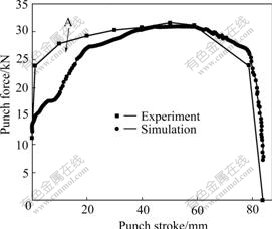
Fig.2 Comparison of punch forces from experiment and optimization using Al6016-T4

Fig.3 Loading path of liquid pressure in die cavity for optimization using Al6016-T4

Fig.4 Comparison of punch forces from experiment and simulation for verification using Al6016-T4
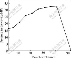
Fig.5 Loading path of liquid pressure in die cavity for verification using Al6016-T4
was used and named as No.36 in the LS-DYNA simulation to consider the effect of anisotropic property. Besides that the four basic parameters x0=[��pb, ��db, k, n] should be considered, because of its highly anisotropic planar property of aluminium alloy Al1050-H0, another three anisotropy factors [r0, r45, r90] were also considered. Here r0 is the anisotropy factor along the rolling direction of 0?, r45 is the anisotropy factor along the rolling direction of 45? and r90 is the anisotropy factor along the rolling direction of 90?. The object function can be defined as Eqn.(10) to minimize the errors of the punch force and the flange ears�� shape in simulation compared with the experimental result. The punch force can be collected along the whole forming process:
 (10)
(10)
where D represents the distance of the ear tip to the centre of the cup and �� is the scaling parameter. The finally optimized data are x=[0.15, 0.049, 178.49, 0.22, 1.03, 0.749, 1.142]. Fig.6 shows the comparison of the punch force between the experiment and the simulation after the optimization. Table 2 lists the comparison of the distances of the formed ear��s tips to the centre of the cup between the simulation and the experiment. It can be found that the optimized material parameters keep reasonable agreement with the experiment.
Table 2 Distances(mm) of ear��s tip to cup centre from experiment and simulation


Fig.6 Comparison of punch forces from experiment and optimization using soft aluminum
5 Analysis of key process parameters�� effect using optimized material parameters
As described above, the optimized parameters from the optimization meet the reality very well and can be used to analyze the forming process and to predict the process windows for the key process parameters. As it is known, in the conventional deep drawing process, some process parameters can be thought having no effect on the forming process, such as the clearance between the punch and the blank holder cpd, blank holder entrance radius rbh. It is very important in the sheet hydroforming because of the function of pre-bulging, as shown in Fig.1(a). In the hydromechanical deep drawing, some key process parameters must be considered, such as the clearance between the punch and the blank holder cpd, blank holder entrance radius rbh, the gap between the blank holder and the die G. To determine optimal values for these parameters experiments will be largely time consuming. Through the analysis in simulation based on the optimized parameters, the design efficiency can be improved to make a robust process design, and the obtained results from simulation will be reliable. The loading path of the liquid pressure in the die cavity is shown in Fig.5 that is collected from the experiment and the bank diameter is 160 mm.
Fig.7 shows the comparison of thickness distributions by using the different clearances between the punch and the blank holder cpb. In this figure, 0.87, 3.48 and 8.70 T mean that the clearances between the punch and the blank holder are 0.87, 3.48 and 8.7 times the original sheet thickness, respectively. It can be seen that there is no big difference for the thickness distributions by using the different cpb. Especially, the wall thickness distributions around the punch nose keep almost similar. Above the punch nose, the wall thickness of sheet is a little larger when using a larger cpb than a smaller cpb. In conventional deep drawing of cylindrical cup, the clearance between the punch and the blank holder is not very important for a successful forming and only for pushing formed part from the punch, and if a too large clearance is selected, the problems will occur when removing the part from the punch. In sheet hydroforming, a larger clearance between the punch and the blank holder is permitted because of the function of the liquid pressure in the die cavity. However, if pre-bulging function is used in sheet hydroforming, too large cpb will induce the over-stretching against pressing direction, which will cause fracture.

Fig.7 Comparison of thickness distributions by using different clearances between punch and blank holder
Fig.8 shows the comparison of thickness distributions by using the different blank holder entrance radii when the clearance between the punch and the blank holder is 3.48 T. In Fig.8, 2.61, 6.08 and 8.70 T mean that the blank holder entrance radii are 2.61, 6.08 and 8.7 times the original sheet thickness, respectively. Although the wall thickness distributions with different blank entrance radii keep almost the same, difference still can be found at the top of formed cups and around the punch nose. This proves that using smaller blank entrance radius is not well contributed to the forming process, which will make the wall thickness distribution thinner, even fracture.
Fig.9 shows the comparison of thickness distributions by using the different gap between the die and the blank holder. In Fig.9, 1.06, 1.30 and 1.74 T mean that the gaps are 1.06, 1.30 and 1.74 times the original sheet thickness, respectively. Obviously, it can be found that in sheet hydroforming with fixed gap between the blank holder and the die, it is better to use a bigger gap. But in reality, the concept of hydro- mechanical deep drawing without a draw die can be proposed and the draw die can be taken instead by liquid in the die cavity.

Fig.8 Comparison of thickness distributions by using different blank holder entrance radii

Fig.9 Comparison of thickness distributions by using different gaps between blank holder and die
As described above, the concept of design in sheet hydroforming is quite different from the conventional deep drawing. The forming zones for some key process parameters such as the clearance between the punch and the blank holder, blank holder entrance radius and the gap between blank holder and die can be enlarged so that a robust process design can be realized.
6 Conclusions
1) Inverse modeling by using the non-linear least square method to define the object function and by using TSSM as an optimization strategy can determine the constitutive parameters combined with the friction coefficients, which keep a reasonable agreement with the reality. The measurement error can be recorded and acquired in this optimization of the sheet hydroforming. Based on the optimized parameters, the sheet hydroforming process can be analyzed more accurately to improve the robust design.
2) In sheet hydroforming using aluminium alloy, a design for a cylindrical cup with a large clearance between the punch and the blank holder is permitted. The optimal forming zone for the blank holder entrance radius can be found, and a die entrance radius should be within a scope in the practical design. Also, the gap between the blank holder and the die can be so large to remove the die if an effective sealing method can be found.
AcknowledgementHelp with the tool set-up by Poul H?jbjerg and measuring by Kjeld B?jer Jensen are greatly appreciated.
References
[1] ZHANG S H, DANCKERT J. Development of hydro-mechanical deep drawing [J]. J Mater Process Technol, 1998, 83: 14-25.
[2] NAKAMURA K, NAKAGAWA T. Sheet metal forming with hydraulic counter pressure in Japan [J]. Annal CIRP, 1987, 36: 191-194.
[3] LANG Li-hai, KANG Da-chang, ZHANG Shi-hong, DAI Kun, WANG Zhong-ren, YUAN Shi-jian. Numerical simulation of cup hydrodynamic deep drawing [J]. Trans Nonferrous Met Soc China, 2000, 10(5): 631-634.
[4] YOSSIFON S, TIROSH J. The maximum drawing ratio in hydroforming process [J]. J Eng Ind Trans ASME, 1990, 112: 47-62.
[5] YOSSIFON S, TIROSH J. Rupture instability in hydroforming deep-drawing process [J]. Int J Mech Sci, 1985, 27: 559-570.
[6] LANG L, KANG D. Key technologies of numerical simulation of cup hydrodynamic deep drawing [J]. Trans Nonferrous Met Soc China, 2000, 10(6): 772-776.
[7] NAKAMURA K, NAKAGAWA T. Sheet metal forming with hydraulic counter pressure in Japan [J]. Annals of the CIRP, 1987, 36: 191-194.
[8] NAKAGAWA T, NAKAMURA K, AMINO H. Various applications of hydraulic counter-pressure deep drawing [J]. J Mater Process Technol, 1997, 71: 160-167.
[9] WANG Z R, TENG B G, YUAN S J, LANG L H, WANG Z J. Simulation of some cases of hydroforming and viscous pressure forming [J]. Journal of Materials Processing Technology, 2003, 150(1): 25-29.
[10] BAY N, JENSEN S S, GRAUSLUND S. Forming limits in hydromechanical deep drawing [J]. Annals of CIRP, 1994, 43: 253-264.
[11] YANG D Y, KIM J B, LEE D W. Investigation into manufacturing of very long cups by hydromechanical deep drawing and ironing with controlled radial pressure [J]. Annals of CIRP, 1995, 44: 44-54.
[12] TIROSH J, KONVALINA P. On the hydrodynamic deep drawing process [J]. Int J Mech Sci, 1985, 27: 595-610.
[13] KANG D C, LANG L H, MENG X F, XUAN J Q. A study on hydrodynamic deep drawing equipment [J]. J Mater Process Technol, 2000, 101: 21-24.
[14] GELIN J C. Modeling and simulation aqua-draw deep drawing process [J]. Annals of the CIRP, 1993, 42(1): 271-277.
[15] TIROSH J, SHIRIZLY A, YOSSIFON S. On recent progress in deep drawing process by fluid pressure assisted methods [A]. ICTP5 [C]. Ohio: Columbus, 1996: 707-782.
[16] YUAN Shi-jian, LIU gang, LANG Li-hui, Numerical Simulation of wrinkling in hydroforming of aluminum alloy tubes [J]. Trans Nonferrous Met Soc China, 2003, 13(S1): 152-156.
[17] LANG L H. Hydroforming highlights: sheet hydroforming and tube hydroforming [J]. Journal of Materials Processing Technology, 2004, 151(1-3): 165-177.
[18] EI-DOMIATY A. Improvement of deep-drawability by radial pressurized fluid [J]. Int J Mach Tools Manuf, 1995, 35(5): 739-749.
[19] YOSSIFON S, TIROSH J. Buckling prevention by lateral fluid pressure in deep drawing [J]. Int J Mech Sci, 1985, 27(3): 177-184.
[20] TIROSH J, SHIRIZLY A, BEN-DAVID D, STANGER S. Hydro-rim deep-drawing processes of hardening and rate-sensitive materials [J]. Int J Mech Sci, 2000, 42: 1049-1067.
[21] DANCKERT J. Hydromechanical deep drawing with uniform pressure on the flange [J]. CIRP Annals-Manufacturing Technology, 2000, 49: 14-19.
[22] LANG L H. Sheet-Metal Hydrodynamic Deep Drawing and the Numerical Simulation of the Forming Process [D]. Harbin: Harbin Institute of Technology, 1998. (in Chinese)
[23] HUSHENS J. On the use of product structure in secant methods for nonlinear least squares problems [J]. SIAM J Optim, 1994(4): 1-79.
[24] YABE H, OGASAWARA H. Quadratic and superlinear convergence of the huschens method for nonlinear least squares problems [A]. Computational Optimization and Applications [M]. Holand: Kluwer Academic, 1998.
[25] KRISTENSEN B E. Filtering and inverse modeling [M]. Aalborg University: Department of Production, 2002.
(Edited by LI Xiang-qun)
Foundation item: Project(9901351) supported by the Hydromechanical Deep Drawing without a Draw Die; Project(1057001) supported by the National Natural Science Foundation of China
Corresponding author: LANG Li-hui; Tel: +86-10-82317704; E-mail: lang@buaa.edu.cn
