
Trans. Nonferrous Met. Soc. China 31(2021) 1806-1817
Parametric study of gas-liquid two-phase flow field in horizontal stirred tank
Zhi-bin CHEN1, Hong-jie YAN1, Ping ZHOU1, Ping YANG2, Jie-hui DING2, Jia LIU1, Liu LIU1
1. School of Energy Science and Engineering, Central South University, Changsha 410083, China;
2. Shenzhen Zhongjin Lingnan Non-ferrous Metal Company Limited, Shenzhen 518040, China
Received 24 June 2020; accepted 30 December 2020
Abstract:
Based on Fluent software, the gas-liquid two-phase flow in the horizontal stirred tank was simulated with SST k-�� turbulence model, Eulerian-Eulerian two-fluid model, and multi-reference flame method. The mixing process in the tank was calculated by tracer method. The results show that increasing the rotating speed or gas flow is conducive to a more uniform distribution of the gas phase and accelerates the mixing of the liquid phase. When the rotating speed exceeds 93 r/min, the relative power demand remains basically constant. The change in the inclination angle of the upper impeller has minimal effect on the gas phase distribution. When the inclination angle is 50��, the relative power demand reaches the maximum. An appropriate increase in the impeller distance from the bottom improves the gas holdup and gas phase distribution but increases the liquid phase mixing time.
Key words:
horizontal stirred tank; gas-liquid two-phase flow; Eulerian-Eulerian two-fluid model; multiple reference frame method;
1 Introduction
With the continuous development of the zinc smelting industry and the continuous increase in the demand for zinc resources, high-grade zinc-bearing mineral resources are becoming scarcer. The use of low-grade and associated resources to extract zinc metal has become a sustainable trend in the zinc smelting industry. Zinc hydrometallurgy technology has advantages such as low cost, a wide range of suitable ore grades, high recovery rate, and high level of automation in the production process [1]. It has been widely used in the zinc smelting industry in China and other countries, with an output accounting for more than 45% of the total zinc output in the world [2]. The stirred tank is the primary component of the leaching process for zinc hydrometallurgy. During the leaching process, the gas is injected into the tank by the oxygen lance at the tank bottom, resulting in a complex multiphase flow inside the tank, and interacts with the liquid phase and solid phase in the tank in a series of physical and chemical reactions [3-5]. In the actual production process, due to the closed nature of the stirred tank, it is difficult to control the complex multiphase flow behavior in the tank using only experience and the limited testing methods, which greatly hinders the improvement of the on-site operation and the further optimization of the stirred tank [6]. With the recent rapid improvements in computer technology, computational fluid dynamics (CFD) has gradually become an important research method for the visualization and parameter optimization of metallurgical processes. Its global information acquisition can provide an effective means for the improvement of the on-site operation and the further optimization of the stirred tank.
CFD technology has been widely used in the simulation of stirred tank flow field. SHI and ROLAND [7] successfully predicted the phase velocity and gas holdup in the experimental scale stirred tank by using the modified turbulence model and traction force model. SHI and ROLAND [8] also proved that CFD can successfully reproduce the solid-liquid two-phase flow behavior in the stirred tank, including the solid velocity, volume fraction, liquid velocity and turbulence parameters. OCHIENG et al [9] investigated the effects of the height of the impeller from the bottom on the mixing efficiency, using CFD technology and used laser Doppler velocimetry (LDV) to effectively validate the mathematical model. ZHAO et al [10] compared the improved intermediate impeller (special oblique baffle) with the standard intermediate impeller by using CFD, and found that the improved impeller promoted the fluid circulation and had lower energy consumption. For industrial-scale stirred tanks, MARION et al [11] used CFD to study single-phase flow behavior of the multistage stirred tank, and found that the vertical impeller used to strengthen impeller structure had quite positive influence on axial circulation. CHEN and XIAO [12] performed numerical calculations on the homogeneous macroscopic flow field in a side-entering stirred tank, analyzed the reasons for the formation of dead zones in the tank, and comparatively analyzed the influence of various mixing impellers on the stirring power and mixing time. Furthermore, few studies on the gas-liquid flow behavior in industrial-scale horizontal stirred tank have been reported.
To improve the operation efficiency of the horizontal stirred tank, it is necessary to explore its flow field. In this work, a three-dimensional mathematical physical model has been developed to describe the gas-liquid flow process in horizontal stirred tank, and the influence of operation and structure parameters on flow characteristics is obtained by numerical simulation.
2 Numerical methodology
2.1 Physical model
The research object is a horizontal leaching stirred tank in a factory. The main structure and impeller structure of the stirred tank are shown in Fig. 1. The diameter of the stirred tank is D, and the length is 1.5D. One baffle plate is distributed on the wall of the tank. A double-layer structure is used for the impeller. The upper axial impeller has 45�� fourfold impellers, and the lower runoff impeller has six flat impellers. The gas is injected into the tank from the oxygen inlet at the bottom of the tank.
Based on the Gambit 2.4.6, a structured hexahedral mesh and an unstructured tetrahedral mesh are used for the computing area. The total number of nodes is 1.2��106 (Fig. 1(b)). Based on the characteristics of the rotation of the impellers in the stirred tank, the multiple reference frame (MRF) method is used to set the area where the double-layer impellers are located as the dynamic reference system, and the remaining areas are set as the static reference system.
2.2 Mathematical model
2.2.1 Basic equations
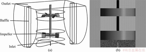
Fig. 1 Schematic diagrams of stirred tank (a) and computational mesh (b)
ANSYS Fluent 18.0 is used to simulate the two-phase flow process in the stirred tank, and the research object is simplified as follows:
(1) The production process is continuous and basically stable;
(2) Under the action of the gas and impellers, the temperature in compartment does not change much, and thus, the effect of the changes in temperature on the gas-liquid two-phase flow field is ignored;
(3) The liquid level in the tank is basically stable, and fluctuations in the liquid level are not considered.
The Eulerian-Eulerian model is used to describe the gas-liquid two-phase flow in the tank. The continuity equation is
 (1)
(1)
where ��i denotes the phase density for phase i, ��i denotes the phase fraction, and ui denotes the phase velocity for phase i.
The gas-liquid momentum equation is

 +
+
 (2)
(2)
where ��i denotes the phase volume fraction for phase i; p denotes the pressure;  denotes the stress-strain tensor for phase i; g is the acceleration due to gravity; n is the number of the phase, and n=2 in this work; vij and vji are the interphase velocities; Fi denotes the Coriolis force and centrifugal force in the rotated reference coordinate system; m��ij represents the mass transfer from phase i to phase j per unit volume per unit time and is zero in this study; Rji represents the interphase force, and Rji=K1gu1g, in which u1g is the gas-liquid relative velocity and K1g is the interphase exchange coefficient, which is described by the model proposed by TOMIYAMA et al [13]. Due to the large difference between the densities of the gas and liquid phases, the virtual mass force (Fvm.i) cannot be ignored, and the coefficient of the virtual mass force (CVM) is set to be 0.5 based on the numerical simulation results of MOUGIN and MAGNAUDET [14]. Flift denotes the lift force and in this study, it is described by the model proposed by TOMIYAMA et al [15]. Fg represents the turbulent dissipation force and is described by the model proposed by BURNS et al [16].
At the oxygen inlet, the Reynolds number Re=13600>2300, and the flow is turbulent. Therefore, this study uses the shear stress transport (SST) k-�� turbulence [17] model to describe the turbulent process in the stirred tank. In the SST k-�� turbulence model, the transport equations of the turbulent kinetic energy (k) and turbulence frequency (��) need to be solved. The specific forms of the equations are as follows:
k equation:

 (3)
(3)
�� equation:

 +
+
 (4)
(4)
where some independent variables, the density ��i and the velocity vector ui can be treated as known quantities; Pk is a turbulence-induced term; ��k and ���� are the diffusion coefficients for k and ��, respectively; F1 is the mixed function and is zero when the current research object is single phase; C��P and C��D are constants;  is the turbulent viscosity; ����2 is the turbulent Prandtl constant;
  is the user-difined source term.
2.2.2 Mixing time model
The mixing time is an important indicator of the speed of the mixing of the materials in the tank [18]. To determine the mixing time in the stirred tank, monitoring points are usually selected at various locations in the tank, and the mixing process is reflected by the concentration response curve. The mixing time is defined as the time required for the difference between the concentration of the monitoring points and the concentration of the final uniform mixing to come within ��5%.
When the CFD is used to simulate the mixing time, because the tracer has no effect on the flow field distribution in the stirred tank, in the process of numerical simulation, the steady-state flow field can be used as the basis, and the mixing time can be determined by calculating the transport equation of the nonsteady-state mass component of the tracer:
 (5)
(5)
where t represents the time, Ji represents the mass diffusion flux of the relative mass average speed and Yi represents the mass of material i.
2.3 Boundary conditions
Based on the on-site conditions and flow characteristics, the corresponding boundary conditions are set for Eq. (1) and Eq. (2), as shown in Fig. 2. The specific definitions are as follows:
(1) Inlet boundary (velocity inlet boundary): The inlet velocity is 17.17 m/s.
(2) Outlet boundary (degassing boundary): The degassing boundary is used to simulate a free surface, and the gas phase can escape through the boundary.
(3) Wall boundary: The solid wall surface in the tank is set to be under no-slip boundary conditions.
(4) The liquid phase is zinc sulfate solution with density of 1350 kg/m3 and viscosity of 10 mPa��s. The gas phase is oxygen under high pressure with density of 4.89 kg/m3 and viscosity of 0.025 mPa��s.
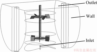
Fig. 2 Definitions of boundary location
3 Model validation
The closed nature of the on-site stirred tank makes it particularly difficult to directly obtain experimental data on the flow in the tank. Therefore, to verify the reliability of the mathematical model developed in the previous section, a laboratory- scale stirred tank was numerically simulated, and the simulation results were compared with experimental data. In this study, the experimental stirred tank of MONTANTE et al [19] was modeled at a model ratio of 1:1 (as shown in Fig. 3), and numerical simulation was performed. The simulation results were compared with the fluid velocity monitored at various locations in the experiment (2r/Dt=0.5, 0.52 and 0.92), which tested the accuracy of the model. Comparisons between the simulation results and experimental data are shown in Figs. 4 and 5. It can be observed that the gas-liquid two-phase axial and radial velocities obtained by numerical simulation are in good agreement with the experimental data. This shows that the developed mathematical model can accurately simulate the flow conditions in the tank.
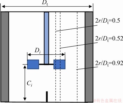
Fig. 3 Schematic diagram of single-layer impeller stirred tank
4 Results and discussion
4.1 Flow field and gas holdup
To facilitate the observation of the flow field in the tank, a cross-section and longitudinal section of the tank are selected as the characteristic surfaces, as shown in Fig. 6.
Figure 7 shows the vector diagram of the liquid phase in the tank. Under the mixing action of the impellers, two main circulation areas form in the liquid phase: one under the lower impeller and one between the two impellers. At the lower impeller, the liquid phase at the impeller edges entrains the surrounding fluid during the flow process and expands around the stirred tank. After impacting the tank wall, the liquid phase is separated into two strands: one strand flows downward and the other flows upward along the tank wall. After reaching the liquid level or the tank bottom, the fluid turns and flows back to the impeller area along the axial direction. It can be observed from the overall flow pattern of the fluid that the calculation results are consistent with the experimental results for the flow field formed by typical axial impeller and runoff impeller [20,21], successfully reproducing the typical characteristics of the turbine mixing flow field. The maximum velocity of the liquid phase appears near the edge of the impeller, indicating that the liquid phase flow in this area is the most violent.
The distribution of the gas holdup can reflect the gas dispersion and mass transfer characteristics. Figure 8 shows the gas holdup distribution in the cross-section and longitudinal section of the tank.
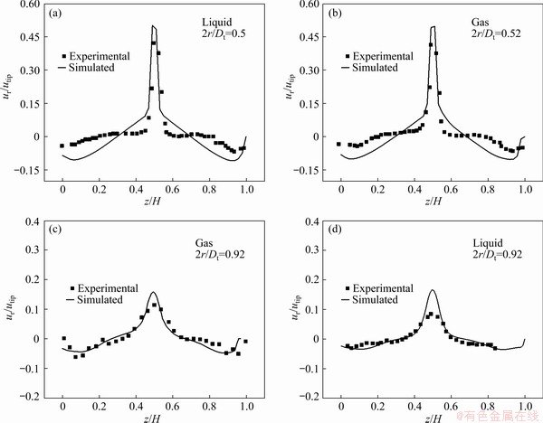
Fig. 4 Comparison between gas-liquid radial velocities of simulation results and experimental results
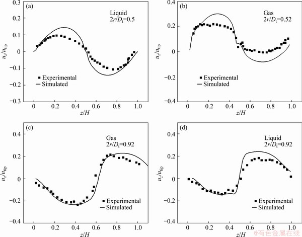
Fig. 5 Comparison between gas-liquid axial velocities of simulation results and experimental results

Fig. 6 Schematic diagram of cross-section and longitudinal section of stirred tank
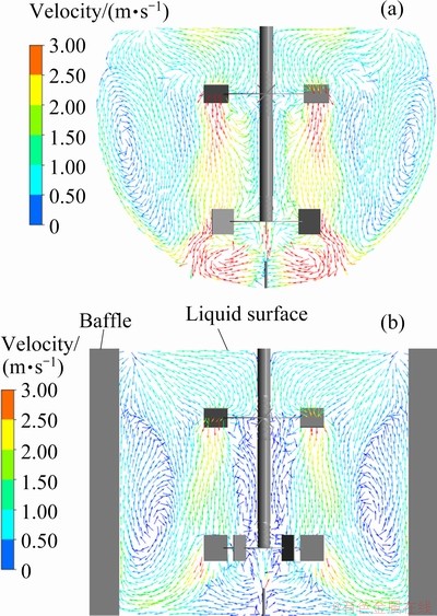
Fig. 7 Diagrams of liquid velocity vectors of cross-section (a) and longitudinal section (b)
It can be observed that the gas phase is unevenly distributed on the tank and is concentrated on the bottom of the tank. After the gas phase is injected into the tank from the oxygen inlet under the impeller, it is hindered by the disc of the lower impeller and thus accumulates under the impeller, diffuses around the liquid phase, and rises along the tank wall into the circulation area between the two layers of impellers. Combined with the diagram of the gas holdup distribution in the longitudinal section in Fig. 8(b), the baffle increases the shear strength of the liquid phase flow, causing more gas to migrate to the center of the tank. Above the impellers, the disc of the upper impeller prevents the liquid phase from flowing downward, and hence, a small portion of the gas phase is concentrated above the disc.

Fig. 8 Distributions of gas holdup on cross-section (a) and longitudinal section (b)
4.2 Mixing process of liquid phase
Since the mass is transferred among the various stirred tank compartments through overflow, a liquid phase tracer feed point is set at the overflow port above the baffle (as shown in Fig. 9), and five tracer concentration monitoring points are installed behind the baffle on the other side to observe the mixing process of the liquid phase. These five monitoring points include both a gentle flow area and an intense flow area (P5), and therefore, the mixing process of the liquid phase can be reasonably reflected.
Figure 10 shows the tracer concentration response curves of various monitoring points. The mixing of the liquid phase is a process from the local to the whole, and the mixing speed differs for the monitoring points at various positions. The concentration response curve of the monitoring point located near the impeller (P5) fluctuates the most drastically, and the curve rises quickly to a high peak value. This is because the flow in this area is more intense than that in other areas, and the tracer mass transfer rate is faster, resulting in accelerated zinc leaching. The P3 monitoring point is located in the circulation area between the two layers of impellers. This area is located in the gentle flow area. The concentration response curve increases slowly with time, with a gradual transition to the final equilibrium. The tracer mass transfer rate at this location is the slowest, and thus, the mixing time here is the longest. In the practical production process, the monitoring points should be reasonably set up based on the production needs to avoid excessive stirring or insufficient stirring.

Fig. 9 Distributions of tracer feed points and concentration monitoring points
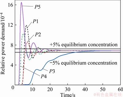
Fig. 10 Tracer concentration response curves
4.3 Analysis of operation and structural parameters
The operating parameters and structural parameters of the horizontal stirred tank directly affect the flow of the liquid phase and the distribution of the gas phase in the tank, which has an important influence on the stirring ability of the stirring impeller. Based on the numerical simulation results for basic working conditions, the influence of the structural parameters and operating parameters (rotating speed, gas flow, inclination angle of the upper impeller, and the height of impeller from the bottom) on the flow field in the tank is analyzed.
Through the introduction of the mixing time, dispersion coefficient and relative power demand (RPD), the fluid flow behavior and gas phase distribution in the tank are assessed. The mixing time characterizes the mixing status of the liquid phase. The smaller the mixing time is, the faster the material mixing is.
The dispersion coefficient C reflects the dispersion of the gas phase in the tank [22]:
 (6)
(6)
where  is the average gas holdup, and �� is the standard deviation:
 (7)
(7)
where �� is the local gas holdup. A larger C indicates a worse uniformity in the gas holdup distribution. Injecting gas into the stirred tank reduces the mixing power compared to that of the pure liquid phase. The RPD is defined as the ratio of the power demand after ventilation to the power demand before ventilation. The value of RPD is mainly affected by two aspects: the size of the cavitation behind the impeller and the average density of the liquid phase in the stirred tank [23]. The smaller the RPD value is, the greater the decrease in power after mixing, which reduces the conveying capacity of the impeller. Thus, a smaller RPD value indicates worse gas-liquid dispersion and mixing.
4.3.1 Rotating speed
The rotating speed is an important operating parameter in the leaching process. In the actual industry, the rotating speed is 83 r/min. Since a variable frequency motor is used in the actual industry, the rotating speed can be adjusted according to production needs. To investigate the effect of rotating speed on the flow field and gas phase distribution in the tank, in this study, the rotating speeds of 63, 73, 83, 93 and 103 r/min are selected.
As shown in Fig. 11, as the rotating speed increases, the gas holdup in the tank gradually decreases, which is inconsistent with the experimental results of ZHENG [24]. This difference mainly occurs because the flow field of a horizontal tank is different from that of a vertical tank. As the rotating speed increases, more gas is entrained into the circulation area between the two impellers, which makes it easier for the gas phase to escape the liquid surface, reducing the residence time of the gas phase in the tank. Increasing the rotating speed enhances the dispersion of the surrounding fluid caused by the impeller. Therefore, the dispersion coefficient in the stirred tank gradually decreases, and the gas phase distribution is more uniform.
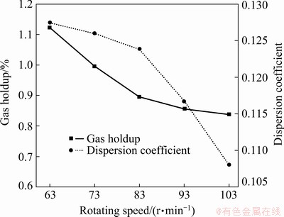
Fig. 11 Gas holdup and dispersion coefficient at various rotating speeds
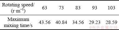
The relative power demands at different rotating speeds are compared, as shown in Fig. 12. The relative power demand increases with the rotating speed, mainly because increasing the rotating speed reduces the size of the cavitation formed behind the impellers and increases the contact area between the impeller and the liquid phase. When the rotating speed exceeds 93 r/min, the influence of rotating speed on relative power demand is insignificant. RAO and JOSHI [25] investigated the effect of rotating speed on the mixing time and the results show that the mixing time decreases with increasing rotating speed. In this work, the effect of the rotating speed on the mixing time is studied, and the relevant results are shown in Table 1. Table 1 shows that an increase in the rotating speed shortens the mixing time of the liquid phase. This occurs because increasing rotating speed increases the intensity of the turbulence, resulting in a faster liquid phase circulation rate, which thereby shortens the mixing time.

Fig. 12 Relative power demand at various rotating speeds
Table 1 Maximum mixing time under different rotating speeds
4.3.2 Gas flow
The gas flow directly affects the distribution of the gas phase in the tank. In this work, four levels of gas flow (80, 180, 280 and 380 m3/h) are selected to analyze the influence of the gas flow on the flow field in the tank.
Figure 13 shows the influence of the gas flow on the gas holdup and dispersion coefficient. The gas holdup increases with increasing gas flow, which is consistent with the experimental results of CHEN et al [26]. When the gas flow is 380 m3/h, the gas holdup in the tank reaches 1.7%. However, the gas phase dispersion coefficient also increases with the gas flow. This occurs because at low gas flow, as the gas flow increases, more gas phase is accumulated under the impeller, and thus, the gas phase dispersion uniformity is worse.

Fig. 13 Gas holdup and dispersion coefficient under various gas flow conditions
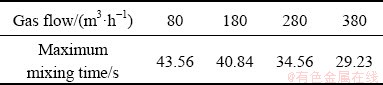
Figure 14 shows that as the gas flow increases, the relative power demand gradually decreases. LONG et al [27] believed that an increase in gas flow increases the size of the cavitation behind the impeller, leading to a reduction in the average density of the liquid phase, and therefore, a reduction in the gas power of the impeller. In addition, as shown in Table 2, increasing the gas flow increases the degree of turbulence in the fluid flow and accelerates the mixing of the liquid phase.
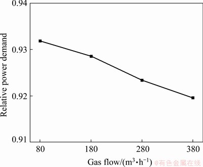
Fig. 14 Relative power demand under various gas flow conditions
Table 2 Maximum mixing time under different gas flows
4.3.3 Inclination angle of upper impeller
For the flow field in the tank, the upper impeller provides the main driving force that causes the intermediate circulation area of the impellers. To investigate the influence of the inclination angle of the impeller on the flow field in the tank, three angles of inclination with respect to the horizontal, 40��, 45�� and 50�� are selected.
As shown in Fig. 15, an increase in the inclination angle of the upper impeller causes a decrease in the gas holdup in the tank. This mainly occurs because a larger inclination angle reduces the strength of the axial flow in the tank, so that it is faster for the gas phase to pass through the circulation area between the two layers of the impeller and escape from the liquid phase. Additionally, increasing the inclination angle causes the gas phase dispersion coefficient to decrease, but the overall degree of change is limited.
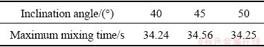
Figure 16 shows the relative power demands of the upper impeller at various angles of inclination. It is shown that the relative power demand of the impeller increases with increasing inclination angle. This occurs because increasing the inclination angle of the upper impeller reduces the intensity of the axial flow, making it easier for the gas phase below the impeller to pass through the impeller. As a result, the size of cavitation behind the lower impeller is reduced, and the relative power demand is promoted. Table 3 shows that the inclination angle of the impeller has minimal effect on the residence time of the liquid phase.
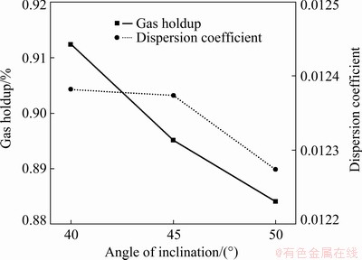
Fig. 15 Gas holdup and dispersion coefficient under various inclination angle conditions
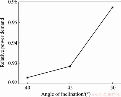
Fig. 16 Relative power demand at different angles of inclination
Table 3 Maximum residence time under different inclination angle conditions
4.3.4 Height of impeller from bottom
The height of the impeller from the bottom is another important parameter in the stirred tank. Generally, the height from the bottom (L) must be less than 1.5 times the impeller diameter (D). In this work, four heights from the bottom, i.e., 0.4D, 0.5D, 0.6D and 0.7D, are selected for numerical simulation.
Figure 17 shows that as L increases from 0.4D to 0.7D, the accumulation of the gas phase below the impeller is significantly relieved, and more gas phase is immersed in the circulation area between the two layers of impellers. RAO and JOSHI [25] believed that this mainly occurs because as the height of the impeller from the bottom increases,the space under the impeller increases. The gas phase has more space to expand under the impeller, and the gas phase distribution is more uniform. Therefore, an increase in the impeller height from the bottom causes the gas phase at the bottom to be better dispersed in the solution, which facilitates zinc leaching. Additionally, this slows down the erosion and wear of the internal wall and impeller caused by the bottom fluid.
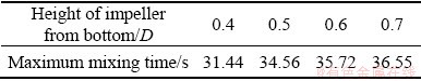
Figure 18 shows the effect of the height of the impeller from the bottom on the power characteristics. It is indicated that the relative power demand decreases first and then increases with the height, with a sharp increase as the height changes from 0.6D to 0.7D. This occurs because as the height of the impeller from the bottom increases, the size of the cavitation formed behind the impeller decreases, and liquid-induced resistance of the impeller increases, resulting in increased relative power demand. When the height exceeds a certain value, the impeller almost only mixes the liquid phase, and at this value, the power is close to that before ventilation. Table 4 shows that as the height of the impeller from the bottom increases, the liquid phase mixing time gradually increases. When the height is larger than 0.5D, the changes in the mixing time are not obvious, which is consistent with the experimental results of REWATKAR and JOSHI [28].
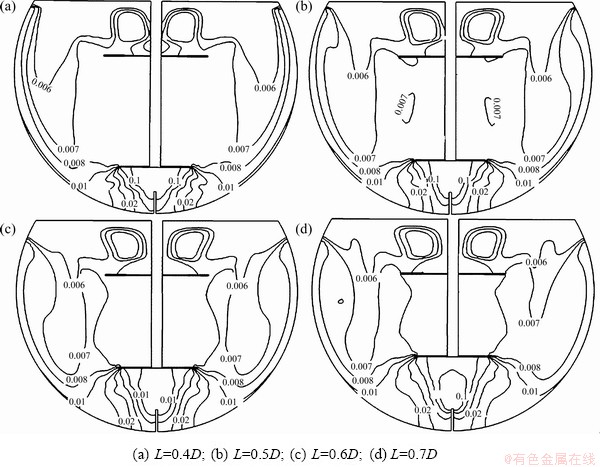
Fig. 17 Cross-sectional gas holdup at various heights of impeller from bottom
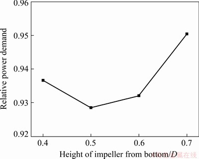
Fig. 18 Relative power demand under various heights of impeller from bottom
Table 4 Maximum residence time under various heights of impeller from bottom
5 Conclusions
(1) The gas holdup in the tank decreases as the rotating speed increases, but when the rotating speed exceeds 83 r/min, further increase has no significant effects on the gas holdup. Increasing the rotating speed can shorten the mixing time of the liquid phase, which improves the zinc leaching rate.
(2) Increasing the gas flow increases the gas holdup in the tank and accelerates the mixing of the liquid phase in the tank. When the ventilation volume is 380 m3/h, the mixing time reaches the minimum value of 29.23 s.
(3) The inclination angle of the upper impeller has no significant effect on the distribution of the gas phase. The mixing capacity of the impeller increases with increasing inclination angle of the upper impeller. The simulation results show that this effect is optimal when the inclination angle is 50��.
(4) Increasing the height of the impeller from the bottom increases the gas holdup in the tank, improves the gas phase distribution, and increases the contact area of the gas-liquid two phases, thereby increasing the leaching rate of zinc. However, as the height increases, the relative power demand decreases, and the liquid phase mixing time increases. After the distance exceeds 0.5D, there are minimal changes in the mixing time.
Acknowledgments
This work was financially supported by the Fundamental Research Funds for the Central Universities of Central South University, China (No. 2020zzts515).
References
[1] BUBAN K R, COLLINS M J, MASTERS I M, TRYTTEN L C. Comparison of direct pressure leaching with atmospheric leaching of zinc concentrates [C]// DUTRIZAC J E. Lead&Zinc 2000. Pittsburg: TMS, 2000: 727-738.
[2] ZHANG Xiu-wu, YANG Lin-sheng, LI Yong-hua, LI Hai-rong, WANG Wu-yi, GE Quan-sheng. Estimation of lead and zinc emissions from mineral exploitation based on characteristics of lead/zinc deposits in China [J]. Transactions of Nonferrous Metals Society of China, 2011, 21(11): 2513-2519.
[3] ZHANG Jin-xia, ZOU Xuan, NIU Fu-sheng. Leaching behavior and leaching kinetics of zinc from zinc-bearing dust [J]. The Chinese Journal of Nonferrous Metals, 2018, 28(8): 1688-1696. (in Chinese)
[4] NIMA S, JAVAD M, MEHDI O. Kinetics of zinc sulfide concentrate direct leaching in pilot plant scale and development of semi-empirical model [J]. Transactions of Nonferrous Metals Society of China, 2017, 27(10): 2272-2281.
[5] FU Zhong-meng, DENG Zhi-gan, WEI Chang, LI Xing-bin, LI Cun-xiong, FAN Gang. Simultaneous leaching of zinc residue and zinc concentrate and oxidative conversion behavior [J]. The Chinese Journal of Nonferrous Metals, 2018, 28(10): 2086-2093. (in Chinese)
[6] CAO Xiao-chang, ZHANG Ting-an, ZHAO Qiu-yue. Computational simulation of fluid dynamics in a tubular stirred reactor [J]. Transactions of Nonferrous Metals Society of China, 2009, 19(2): 489-495.
[7] SHI Peng-yu, ROLAND R. Bubbly flow in stirred tanks: Euler-Euler/RANS modeling [J]. Chemical Engineering Science, 2018, 190: 419-435.
[8] SHI Peng-yu, ROLAND R. Solid-liquid flow in stirred tanks: Euler-Euler/RANS modeling [J]. Chemical Engineering Science, 2020, 227: 1-23. 10.1016/j.ces.2020.115875.
[9] OCHIENG A, ONYANGO M S, KUMAR A, KIRIAMITI K, MUSONGE P. Mixing in a tank stirred by a Rushton turbine at a low clearance [J]. Chemical Engineering and Processing, 2008, 47(5): 842-851.
[10] ZHAO Hong-liang, ZHANG Zi-mu, ZHANG Ting-an, LIU Yan, GU Song-qing, ZHANG Chao. Experimental and CFD studies of solid�Cliquid slurry tank stirred with an improved Intermig impeller [J]. Transactions of Nonferrous Metals Society of China, 2014, 24(8): 2650-2664.
[11] MARION A G, RODOLPHE S, CATHERINE X, PHILIPPE H, BERTRAND L, PHILIPPE S. CFD analysis of industrial multi-staged stirred vessels [J]. Chemical Engineering and Processing: Process Intensification, 2006, 45(5): 415-427.
[12] CHEN Jia, XIAO Wen-de. Numerical simulation of turbulent flow field in industrial-scale side-entering stirred tank [J]. Chemical Engineering (China), 2013, 41(8): 43-47. (in Chinese)
[13] TOMIYAMA A, KATAOKA I, ZUN I, SAKAGUCHI T. Drag coefficients of single bubbles under normal and micro gravity conditions [J]. JSME International Journal Series B: Fluids and Thermal Engineering, 1998, 41(2): 472-479.
[14] MOUGIN G, MAGNAUDET J. The generalized Kirchhoff equations and their application to the interaction between a rigid body and an arbitrary time-dependent viscous flow [J]. International Journal of Multiphase Flow, 2002, 28(11): 1837-1851.
[15] TOMIYAMA A, TAMAIA H, ZUN I, HOSOKAWA S. Transverse migration of single bubbles in simple shear flows [J]. Chemical Engineering Science, 2002, 57(11): 1849-1858.
[16] BURNS A D, FRANK T, HAMILL I, SHI Jun-mei. The favre averaged drag model for turbulent dispersion in Eulerian multi-phase flows [C]// The 5th International Conference on Multiphase Flow. Yokohama, 2004: 392-409.
[17] MENTER F R. Two-equation eddy-viscosity turbulence models for engineering applications [J]. AIAA Journal, 1994, 32(8): 1598-1605.
[18] PATWARDHAN, ASHWIN W. Prediction of residence time distribution of stirred reactors [J]. Industrial & Engineering Chemistry Research, 2001, 40(24): 5686-5695.
[19] MONTANTE G, PAGLIANTI A, MAGELLI F. Experimental analysis and computational modelling of gas-liquid stirred vessels [J]. Chemical Engineering Research and Design, 2007, 85(5): 647-653.
[20] AUBIN J, SAUZE L N, BERTRAND J, FLETCHER D F, XUEREB C. PIV measurements of flow in an aerated tank stirred by a down- and an up-pumping axial flow impeller [J]. Experimental Thermal and Fluid Science, 2004, 28(5): 447-456.
[21] RANADE V V, PERRARD M, XUEREB C, SAUZE L N, BERTRAND J. Influence of gas flow rate on the structure of trailing vortices of a Rushton turbine: PIV measurements and CFD simulations [J]. Chemical Engineering Research and Design, 2001, 79(8): 957-964.
[22] GAO Na, BAO Yu-yun, GAO Zheng-ming. Local void fraction in a sparged reactor with a multi-impeller agitator [J]. Journal of Chemical Engineering of Chinese Universities, 2011, 25(1): 11-17. (in Chinese)
[23] BAO Yu-yun, CHEN Lei, GAO Zheng-ming, ZHANG Xin-nian, SMITH J M, KIRKBY N F. Temperature effects on gas dispersion and solid suspension in a three-phase stirred reactor [J]. Industrial & Engineering Chemistry Research, 2008, 43(12): 4270-4277. (in Chinese)
[24] ZHENG Quan. CFD modeling of hydrodynamic characteristics in gas-liquid two-phase reactors [D]. Dalian: Dalian University of Technology, 2016. (in Chinese)
[25] RAO K S M S, JOSHI J B. Liquid-phase mixing and power consumption in mechanically agitated solid-liquid contactors [J]. The Chemical Engineering Journal, 1988, 39(2): 111-124.
[26] CHEN Kai, WANG Jia-jun, GU Xue-ping, FENG Lian-fang, WANG Kai. Study on the gas-liquid separation performance of dual impeller combinations [J]. Chemical Engineering (China), 2004, 32(3): 24-27. (in Chinese)
[27] LONG Jian-gang, BAO Yu-yun, GAO Zheng-ming. Gas-liquid dispersion in a stirred tank with different impeller combinations [J]. Journal of Beijing University of Chemical Technology, 2005, 32(5): 1-5. (in Chinese)
[28] REWATKAR V B, JOSHI J B. Effect of impeller design on liquid phase mixing in mechanical agitated reactors [J]. Chemical Engineering Communications, 1991, 102(1): 1-33.
��ʽ���踪��Һ���������IJ������о�
��־��1���ƺ��1���� Ƽ1���� ƽ2�����ܻ�2���� ��1���� ��1
1. ���ϴ�ѧ ��Դ��ѧ�빤��ѧԺ����ɳ 410083��
2. �������н�������ɫ�����ɷ�����˾������ 518040
ժ Ҫ������Fluent����������SST k-������ģ�͡�ŷ��-ŷ��������ģ�ͺͶ��زο�ϵ������ʽ���踪��Һ��������������ֵģ�⣬������ʾ�ټ����о����ڻ�Ϲ��̡��������������ת�ٻ�������������������ֲ������Ȳ��ӿ�Һ��Ļ�ϡ�������ת�ٳ���93 r/minʱ����Թ������Ļ������䡣��Ҷ����б�ǵı仯������ֲ���Ӱ���С�������Ϊ50�� ʱ����Թ�����������ʵ���߽�Ҷ��߶ȿ�����������ʲ���������ֲ�����������Һ�����ʱ�䡣
�ؼ��ʣ���ʽ���踪����Һ��������ŷ��-ŷ��������ģ�ͣ����زο�ϵ��
(Edited by Bing YANG)
Corresponding author: Liu LIU, Tel: +86-731-88879863, E-mail: l.liu@csu.edu.cn
DOI: 10.1016/S1003-6326(21)65618-2
1003-6326/ 2021 The Nonferrous Metals Society of China. Published by Elsevier Ltd & Science Press
Abstract: Based on Fluent software, the gas-liquid two-phase flow in the horizontal stirred tank was simulated with SST k-�� turbulence model, Eulerian-Eulerian two-fluid model, and multi-reference flame method. The mixing process in the tank was calculated by tracer method. The results show that increasing the rotating speed or gas flow is conducive to a more uniform distribution of the gas phase and accelerates the mixing of the liquid phase. When the rotating speed exceeds 93 r/min, the relative power demand remains basically constant. The change in the inclination angle of the upper impeller has minimal effect on the gas phase distribution. When the inclination angle is 50��, the relative power demand reaches the maximum. An appropriate increase in the impeller distance from the bottom improves the gas holdup and gas phase distribution but increases the liquid phase mixing time.
