

J. Cent. South Univ. (2019) 26: 2354-2367
DOI: https://doi.org/10.1007/s11771-019-4179-3

Integrated yaw and rollover control based on differential braking for off-road vehicles with mechanical elastic wheel
LI Hai-qing(���), ZHAO You-qun(����Ⱥ), LIN Fen(�֗�), XIAO Zhen(Ф��)
College of Energy & Power Engineering, Nanjing University of Aeronautics & Astronautics,Nanjing 210016, China
 Central South University Press and Springer-Verlag GmbH Germany, part of Springer Nature 2019
Abstract:
Aiming at the issue of yaw and rollover stability control for off-road vehicles with non-pneumatic mechanical elastic wheel (MEW), an integrated control system based on fuzzy differential braking is developed. By simplifying the structure of the MEW, a corresponding fitting brush tire model is constructed and its longitudinal and lateral tire force expressions are set up, respectively. Then, a nonlinear vehicle simulation model with MEW is established to validate the proposed control scheme based on Carsim. The designed yaw and rollover control system is a two-level structure with the upper additional moment controller, which utilizes a predictive load transfer ratio (PLTR) as the rollover index. In order to design the upper integrated control algorithm, fuzzy proportional-integral-derivative (PID) is adopted to coordinate the yaw and rollover control, simultaneously. And the lower control allocator realizes the additional moment to the vehicle by differential braking. Finally, a Carsim-simulink co-simulation model is constructed, and simulation results show that the integrated control system could improve the vehicle yaw and roll stability, and prevent rollover happening.
Key words:
Cite this article as:
LI Hai-qing, ZHAO You-qun, LIN Fen, XIAO Zhen. Integrated yaw and rollover control based on differential braking for off-road vehicles with mechanical elastic wheel [J]. Journal of Central South University, 2019, 26(9): 2354-2367.
DOI:https://dx.doi.org/https://doi.org/10.1007/s11771-019-4179-31 Introduction
In recent years, the popularity of the high center of gravity (CG) vehicles such as sport utility vehicle (SUV) and off-road vehicle have significantly increased. These vehicles are subjected to more fatal accidents because of their intrinsic dynamics [1]. The main cause of the vehicle rollover is due to the vehicle manoeuvring at limit handling conditions [2]. Vehicle driving safety is mainly dependent on electronic stability control (ESC), which has attracted wide interest in study and been widely applied on vehicles, especially on passenger cars [3-6]. And the ESC system adopting active yaw stability control (YSC) to achieve yaw stability is one of the most common approaches. For off-road vehicle with high CG, rollovers maybe still occur easily even with ESC [7]. Thus, many approaches have been adopted to prevent rollovers, such as active suspension [8, 9], active stabilizer mechanism [10, 11] and active differential braking [12]. The active suspension and active stabilizer mechanism are direct ways to restrain the vehicle roll motion. Facts proved that it is effective to prevent rollover indirectly by decreasing the lateral acceleration of a vehicle, and braking the target wheels is a possible way to reduce the lateral acceleration when the vehicle is in danger of rollover. Due to the limited effectiveness and the cost of the active suspension for rollover prevention, it is easier to prevent rollover by braking target wheels. Active braking control, of all these approaches, has received the most attention, because it can be easily realized based on a typical ESC system [7].
Regarding rollover stability control (RSC), designing a rollover warning system is very important, which can predict whether the vehicle has a rollover risk in a period of time [13]. Rollover prediction systems have been studied by many researchers. Traditionally, the vehicle load transfer ratio (LTR) has been used as a basis for the design of rollover prevention systems [14]. SUN et al [11] proposed time-to-rollover (TTR) metric for the prediction of vehicle rollover risk, which mainly relied on the estimation of roll states via a linear vehicle model. However, in the prediction methods of LTR or TTR index, only the parameters of the vehicle dynamics at the moment were taken into account, and the judgment of the overall tendency of vehicle states was neglected. LARISH et al [15] developed a predictive load transfer ratio (PLTR) to provide a prediction of rollover propensity, which performs better than the traditional LTR. ZHANG et al [16] proposed a contour line of load transfer ratio (CLTR), which provides a novel approach to quantify the likelihood of vehicle rollover prediction.
To coordinate yaw stability and rollover stability control effectively and realize integrated system to the utmost, it needs to realize integrated control of YSC and RSC [12]. The relationship between RSC and YSC is complex and both are related to the complicated vehicle lateral dynamics. What��s more, the uncertain parameters of sprung mass, road friction coefficient and side-slip angle have an important significance on vehicle chassis electronic control system [11, 17-19]. It also should be made that the integrated control system adapts to any road conditions [20].
A reasonable tire model is a key for vehicle dynamic modeling and control especially for military off-road vehicle with special tires [21]. A key issue in the design of tyres is their capability to sustain intense impact loads [22] and tire other mechanical characteristics. The off-road characteristics cover the adhesion, transition regions, and saturation regions. To simulate the tire forces associated with tire rolling on different road conditions, early researchers have developed a variety of physical models, theoretical models and semi-empirical models to analyze dynamic performances of pneumatic tires [23]. The MEW, designed for a military off-road vehicle, has changed the configuration of conventional tyre and provided a new research idea for improving vehicle safety performance [24, 25]. Compared with pneumatic tires, the calculations of MEW��s longitudinal and lateral forces need some specific parameters and the characteristic data which are incomplete because longitudinal and lateral slip of MEW needs to be redefined by considering the longitudinal, lateral and vertical deformations of treads and elastic supports [26].
Based on the above reasons, a relatively simple physical model, named brush model was utilized to calculate the MEW��s longitudinal and lateral force. An integrated control strategy by coordinating yaw and rollover stability control based on differential braking to realize vehicle rollover stability to the utmost is suggested. The integrated control strategy includes two sub- controllers. The first fuzzy differential braking controller is designed based on individual wheels braking and the second active suspension controller is designed using the warning system of the PLTR. Two sub-controllers are integrated based on fuzzy logic to detect rollover for all sorts of emergency situations. In order to prevent the wheels from locking, the integrated controller also combines ABS control algorithm.
2 Nonlinear vehicle model
The vehicle studied here is an off-road vehicle with ME-wheel. This section describes the modeling process of the off-road vehicle in Carsim software. Since the accuracy of the simulation model can severely affect the evaluation of the proposed integrated control strategy, a nonlinear simulation model is built based on the Carsim environment, which is a commercial software with high simulation accuracy for dynamics simulation [27].
2.1 Carsim off-road vehicle model
The Carsim software package is based on a symbolic mulitbody program, namely VehicleSim (VS) Lisp and involves three relevant elements: VS brower, Carsim databases, and VS solver. The Carsim database is used to select vehicle configuration template and to define the system parameters, the tire-road interactions and the test maneuvers. A stability controller designed in Matlab can also be allowed and accessed to the Carsim database via the VS browser interface.
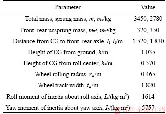
In Carsim model, each of the sprung masses is considered as a rigid body with 6-DOF, namely the longitudinal, lateral and vertical motion, the pitch, roll and yaw motion. The Carsim model also uses detailed nonlinear spring models, nonlinear kinematic relation-ships, and other nonlinear component models. In addition, the nonlinear tire dynamics is represented by the brush model for the off-road vehicle. The suspension systems of off-road vehicles mainly use independent suspension in front axle and leaf springs in rear axle. The spring stiffness values of the front axle and rear axle are set as 146 N/ mm, 60 N/mm, respectively. The whole steering system is front wheel steering with the gear ratio I=20. The important parameters in Carsim are listed in Table 1. The other parameters of off-road vehicle system take the values provided by the ��SUV, Full size�� model generated in the Carsim software package.
Table 1 Parameters and values for off-road vehicle
2.2 Tire model
As a key part of the vehicle model, the tire model is important for simulation accuracy. The brush model is selected to calculate the longitudinal and lateral force. Figure 1 shows the main components of the MEW. The wheel deformation in contact with ground is shown in Figure 2. The longitudinal length of contact area is 2lp. Define  where �� is wheel angular velocities, vx is the longitudinal speed.
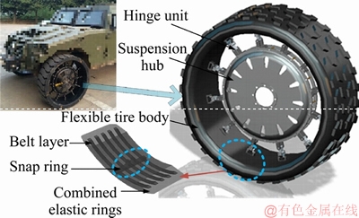
Figure 1 Structure of MEW
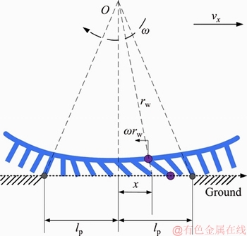
Figure 2 A schematic of tread deformation in longitudinal direction
Based on brush modeling theory, the longitudinal force Fx along the whole contact area can be expressed as:
 (1)
(1)
where cex is the longitudinal stiffness of the elements of the tread. However, Eq. (1) never considers the conditions when longitudinal force is out of the limit of adhesion ��. The sketch of the strains along the contact area is shown in Figure 3.
The adhesion area is located in the front part of the whole contact area. S is the critical point. xs is the longitudinal coordinate. d is the length of the sliding area in longitudinal coordinate. Then, longitudinal force Fx can be expressed as,
 (2)
(2)
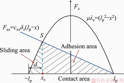
Figure 3 A sketch of strains along contact area of tire
In the case of xs<>p, the contact area is characterized by both area of adhesion and sliding  otherwise the whole contact area will be in sliding condition. When xs=lp, then, d=2lp. Based on brush modeling theory, the longitudinal force Fx along the whole contact area can be expressed as
 (3)
(3)
The wheel deformation in lateral direction is shown in Figure 4. t is the critical point between the sliding and the adhesion area. xt is the longitudinal coordinate of the point in contact area.
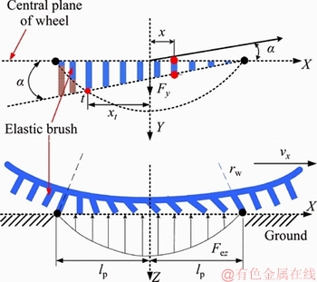
Figure 4 A schematic of tread deformation in lateral direction
As the role of lateral force in lateral direction for the brush, the slip angle is a. Then,
 (4)
(4)
where cey is the lateral stiffness of the elements of the tread.
From Figure 4, in the case of xt<>p, the contact area is also characterized by both area of adhesion and sliding, otherwise, the whole contact area will be in sliding condition. In this case, xt=lp. Define  and the lateral force Fy along the whole contact area can be expressed as
 (5)
(5)
The dynamic mechanical experiments of the ME-Wheel were conducted using a flatbed low- speed tire test rig, as presented in Figure 5.
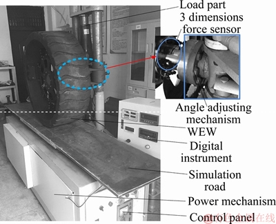
Figure 5 Experimental set-up of tire mechanical characteristics
The specific steps of the tire mechanical properties test rig are as follows: First, demarcates the test bench and sets the test wheel angle to zero before experiment. Second, adjusts slip angle of the test wheel to the assigned by the angle adjustment mechanism and applies the desired load to the wheel by the loading part. Next, drives the simulated pavement moving from the test bench at a stable translation speed by the power mechanism. Furthermore, sets reasonable sampling range and sampling point on simulated pavement and records the tire force of the wheel at each sampling point after the test wheel entering the sampling range. In the end, adjusts the slip angle or vertical load and repeats to test.
By analyzing the experimental data, a fitting model of half long grounding mark and lateral distribution stiffness along with vertical tire forces are established, respectively, as
 (6)
(6)
 (7)
(7)
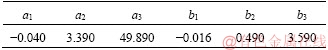
The parameters a1-a3 and b1-b3 are illustrated in Table 2, which were calibrated through tire force tests.
Table 2 Fitted coefficient of brush model
Multiple different longitudinal slip sx from 0 to 0.7 and different slip angle from 0 to 20�� are applied to the ME-Wheel. The applied vertical load is 15 kN. The variation of longitudinal tire force with respect to the longitudinal slip and lateral tire force with respect to the slip angle are illustrated in Figures 6 and 7 .
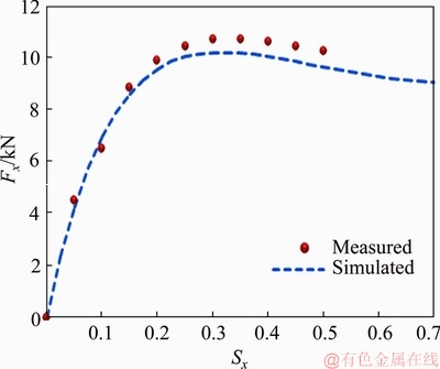
Figure 6 Longitudinal tire force with respect to sx
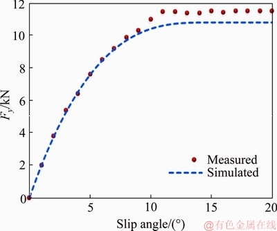
Figure 7 Lateral tire force with respect to slip angle
As for the cornering conditions, different rotational speeds and translational speeds are applied on the ME-wheel and the applied vertical load is 3, 6, 9, 12 and 15 kN, respectively. The variation of longitudinal tire force with respect to the longitudinal slip and lateral tire force with respect to the slip angle are illustrated in Figures 8 and 9.
Finally, the non-linear tire model has been built in Carsim and verified by a real vehicle testing.
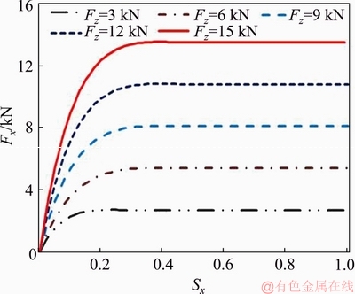
Figure 8 Longitudinal tire force at different longitudinal slip and different vertical tire forces
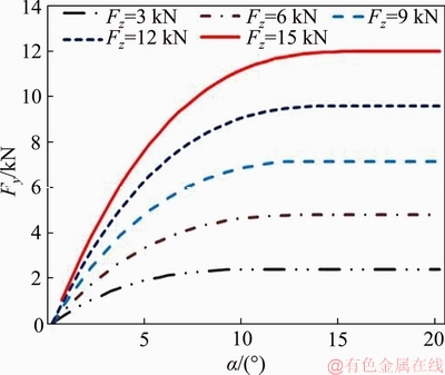
Figure 9 Lateral tire force at different slip angles and different vertical tire forces
Steering wheel angle of step input test is used here for the inspection of the simulated vehicle model prediction abilities. The size of the step angle is 250��, which is shown in Figure 10. The test results and the simulation animations of the steady turning trajectory and radius are shown in Figures 11(a) and (b).
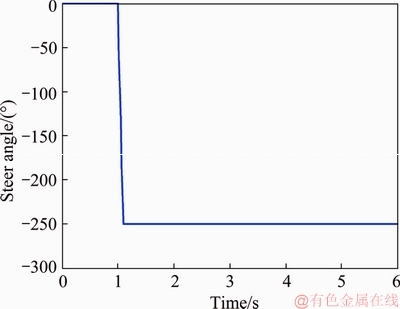
Figure 10 Steering wheel angle step input test
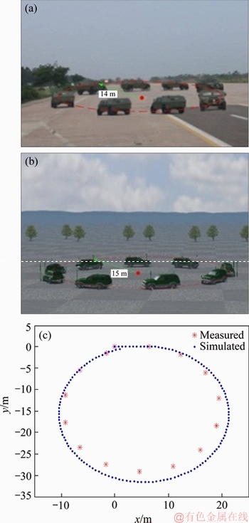
Figure 11 Test results of steady turning trajectory and radius (a), simulation animations of steady turning trajectory and radius (b), steady turning trajectory comparison (c)
It can be found that the difference in both values of steady turning trajectory and radius (Figures 11(a), (b)) by test and Carsim simulation are not very significant. Note that, the Carsim vehicle model is effective compared with the test results and can be used as the simulated model of the off-road vehicle.
To analysis and evaluate the whole dynamics model with ME-wheel built in Carsim, the compared vehicle model with common tyre is also built, which are conducted on the high adhesion coefficient of 0.85 and the initial speed is 60 km/h, respectively. The yaw rate and roll angle response comparison based on different tires (common tyre and ME-wheel) is shown in Figure 12. The lateral force comparisons of the four wheels are shown in Figure 13.
It can be found that the vehicle model concluding the new ME-wheel meets the handling stability requirements and the rollover stability is better than vehicle with common pneumatic tires in high speed conditions.
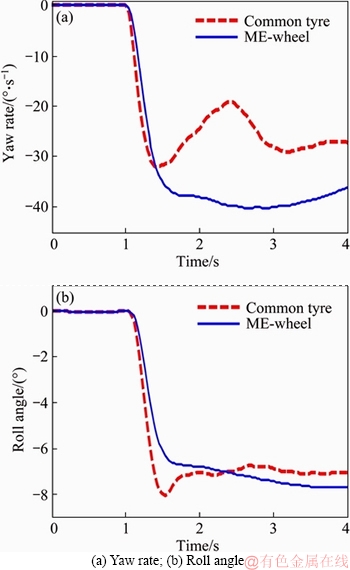
Figure 12 Step input maneuver test by common tyre and ME-wheel:
3 Integrated control algorithm
When a severe rollover occurs and the CG of vehicle is high, the gravity force will exacerbate the roll motion, and the rollover cannot be prevented in time only through YSC and using additional braking moment controller will make it up. The assumed structure shown in Figure 14 contains vehicle modules, a rollover warning system and an integrated fuzzy controller.
3.1 Rollover predictive system
Rollover predictive system warns whether the vehicle has a rollover risk in a period of time according the current driving states of the vehicle.
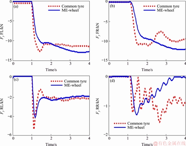
Figure 13 Lateral force comparisons of four wheels (��FL��, ��FR��, ��RL�� and ��RR�� denote the front left wheel, front right wheel, rear left wheel and rear right wheel, respectively)
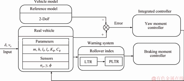
Figure 14 Block diagram of integrated control system
LTR is one of the commonly used rollover index, which is formulated as [16]
 (8)
(8)
where Fzl and Fzr are the left and right vertical tire forces.
Considering that the vertical tire forces are not easy to measure, LTR can also be expressed as [14]
 (9)
(9)
where ay is the lateral acceleration, �� is the roll angle.
The prediction method of LTR, parameters of the vehicle dynamics at the current moment were taken into account only, and the judgment of the overall tendency of the vehicle motion was neglected. Hence, a new PLTR, is developed, which can provide a time advanced measure of rollover. The PLTR is defined as [15]

 (10)
(10)
where  g is yaw rate, �� is the roll angle, d is the steering angle, kf and kr are the cornering stiffness values for the front and rear tires, respectively.
Considering the fact that the calculation of PLTR by Eq. (10) may not be very accurate and the bigger threshold value of PLTRs will make the intervention time by integrated system too late for rollover control. However, if the PLTRs sets too small, which means the control system will always on adjusting even in very safety space. To achieve an enough time for rollover prevention system to prevent the vehicle from rollover, the threshold value of PLTRs is finally set as 0.75.
3.2 Fuzzy active braking control system
The developed control algorithm integrated yaw and rollover stability control based on active braking and the yaw stability control scheme is base of the response of the real vehicle following the response of the reference model. Figure 15 shows the block diagram of the active braking control scheme.
The integrated braking control algorithms, based on the idea of independently decision make firstly and integrated by weight. In other words, roll stability controller decides the needed brake torque independently, and then unifies the yaw moment by way of weight according to fuzzy logic. In order to prevent the wheels from locking, the integrated control algorithm also combines ABS control algorithm.
For the design of yaw stability control, a 2-DoF single-track model is implemented to obtain the reference yaw rate. The desired yaw rate response can be obtained by using the following equation [4]:
 (11)
(11)
where


PID controller is adopted and the corrective yaw moment ��Mz and braking moment ��Mb can be calculated as follows:
 (12)
(12)
 (13)
(13)
The effective error e�� can be calculated as
 (14)
(14)
where 
 .
.
Then, the integrated additional moment Tb can be formulated as
 (15)
(15)
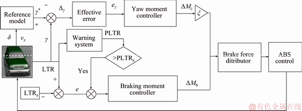
Figure 15 Block diagram of integrated active braking control scheme
where �� is the weight coefficient of the yaw moment. There is another problem, how to get the value of ��.
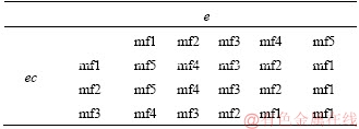
When the rollover propensity is small enough, yaw moment controller can satisfy the request. As roll angle gets bigger, PLTR is bigger than PLTRs, the control system still using yaw moment controller becomes inaccurate. Hence, in this case, it is more efficient to design a controller for all sorts of driving scenarios. In this work, for the input errors of e, five conditions are considered for fuzzification which linguistic variables are assigned to these fuzzy and set as mf1 (too low), mf2 (low), mf3 (normal), mf4 (high), mf5 (too high). And for the input of ec, three conditions are considered for fuzzification and set as mf1 (low), mf2 (normal), mf3 (high). For the output, there were five levels for altering: mf1 (too low), mf2 (low), mf3 (normal), mf4 (high), mf5 (too high). The fuzzy control rules are made in the form of Table 3. The membership functions are presented in Figure 16.
Table 3 Fuzzy control rules for ��
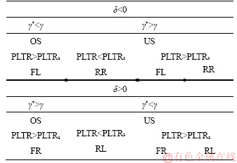
Brake force distributor aims to generate the yaw moment calculated from the yaw moment controller and braking moment from rollover stability controller. Yaw moment controller brakes the outside front wheel to correct Over-Steer and brakes the inside rear wheel to correct Under-Steer, which is decided in Figure 17.
Braking moment controller by distributing the brake force to the target wheel which is efficient is decided in Table 4, correspondingly.
The integrated yaw and rollover controller by distributing the brake force to the right wheel which is efficient is decided in Table 5.
The whole needed brake force is calculated by an integrated controller with a fuzzy controller. Give the corrective yaw moment ��Mz and a braking torque ��Mb to stabilize the vehicle, if the target braking wheels are the same, the brake force can be calculated as
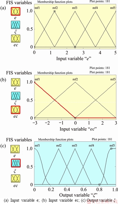
Figure 16 Membership functions in fuzzy logic controller:
 (16)
(16)
if the target braking wheels are different, the brake force on the front axle is given as
 (17)
(17)
and the brake force on the rear axle is given as
 (18)
(18)
Severe braking maneuvers will cause the wheels to lock, resulting in loss of control. In order to prevent the wheels from locking, ABS control is added. Since the modeling of the ABS is not the key content in this paper, the details of the ABS theory are no longer given here, which can be referred to SONG et al [28].
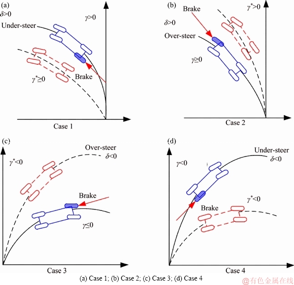
Figure 17 Brake wheels decision for yaw stability:
Table 4 Differential braking control decision for roll stability
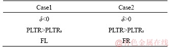
Table 5 Brake wheels decision of brake force distributor
4 Simulation results and analysis
The proposed integrated controller is implemented under the Simulink platform. To analyse and evaluate the proposed integrated control scheme, the manoeuvres of Lane change and Fishhook are tested which are conducted on the high adhesion coefficient of 0.85, respectively.
4.1 Lane change maneuver test
The steer angle which applied to the Carsim model is shown in Figure 18 and the initial speed is 100 km/h.
The yaw rate and roll angle response comparison based on different control methods is shown in Figure 19.
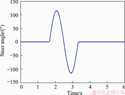
Figure 18 Steer angle input (Nominal gear ratio is 20)
As is shown in Figure 19(b), reduction in peak value of roll angle in the case of YSC and integrated controller with rollover evaluation index of PLTR control are about 10% and less stable of rollover in case of YSC. It also can be found in Figure 19(a) that the yaw rate values of integrated controller and YSC controller are better than the values without controller at 2.3 s, however, the yaw rate responses controlled by integrated controller are not better than the values without controller at 3.1 s. The reason is that the integrated controller, under the same dangerous working condition, enjoys priority in obtaining the braking moment for rollover control, which means the proposed integrated controller has more advantages in rollover control than sideslip control. The brake torque of 4 wheels is shown in Figure 20.
It is noted that the control scheme proposed here can keep the vehicle cornering more stable than the uncontrolled vehicle. The decrease in vehicle rolling moment is bigger than that in YSC control case for the bigger brake force to guarantee the rollover index in a designed range.
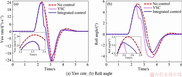
Figure 19 Lane change maneuver test by different controllers:
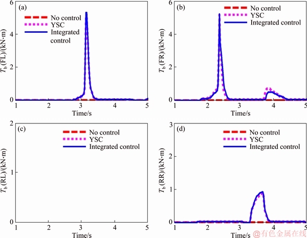
Figure 20 Braking torque of 4 wheels by different controllers
4.2 Fishhook test
A critical scenario has also been generated by a Fishhook maneuver with a maximum steering angle of 288��. The steer angle is shown in Figure 21. The initial speed of the vehicle is 60 km/h. The yaw rate and roll response comparison based on different control methods are shown in Figures 22 and 23.
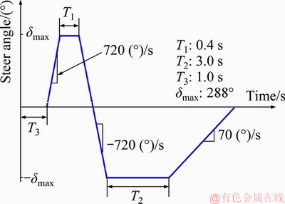
Figure 21 Steer angle input for Fishhook maneuver
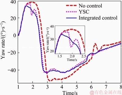
Figure 22 Yaw rate response comparison in Fishhook test
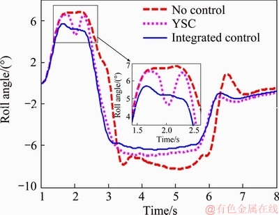
Figure 23 Roll angle response comparison in Fishhook test
It can be found from Figure 23 that reduction in peak value of roll angle in case of integrated control with rollover evaluation index of PLTR is more than 30%, and about 5% in case of YSC, it also can be found in Figure 22 that the yaw value in the peak by the integrated controller is the smallest in the other comparison controllers, which means the integrated controller can earlier adjust the active braking system for sideslip and rollover control. Figure 24 shows the trajectories of the vehicles with integrated controller and without controller at different initial speed. As shown in Figure 24(a), the vehicle with the proposed controller has the smallest lateral slipping and cornering radius than that without controller due to the larger braking input. This fact can also be confirmed by Figure 22.
It can be found from Figure 24(b) that the integrated controller can also prevent rollover occurrence and noted that though the cornering is fast and the vehicle speed is high, the control scheme proposed here can still keep the vehicle in stability while the uncontrolled vehicle will lose stability rapidly and rollover. From the simulation result, it is clear that the integrated controller is successfully designed and shows good control ability and performance.
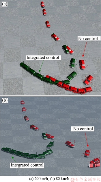
Figure 24 Vehicle trajectories comparisons in Fishhook test based on Carsim vehicle model at different initial speed:
Experimentations will be followed in the next investigation to test and improve the rollover prediction and yaw and roll stability control scheme further. In the first step, hardware-in-the-loop simulation (HILS) in the lab should be conducted to check and regulate the rollover prediction and the controlling laws. After that, field test will be implemented with the manoeuvres in simulations to evaluate the integrated control system.
5 Conclusions
In this paper, an integrated of yaw and roll stability control strategy based on rollover prediction and fuzzy PID for an off-road vehicle with MEW is designed. The prediction system was achieved through a predictive LTR (PLTR) index and a Carsim nonlinear vehicle model. The results can be summarized as follows:
1) Based on brush modeling theory, longitudinal and steady-state cornering mixed model of MEW is established and tested.
2) The Carsim nonlinear vehicle model is built up and tested, and the result shows that the model has very high simulation accuracy.
3) The integrated controller based on fuzzy-PID with rollover evaluation index of PLTR shows a good control ability and performance. Hence, the integrated control system could improve the rollover and yaw stability of the vehicle, and prevent rollover happening.
References
[1] ARIPIN M K, SAM Y M, DANAPALASINGAM K A, PENG K, HAMZAH N, ISMAIL M F. A review of active yaw control system for vehicle handling and stability enhancement [J]. International Journal of Vehicular Technology, 2014(1-4): 1-15.
[2] PARK M, LEE S H, KIM M J, LEE J Y, YI K S. Integrated differential braking and electric power steering control for advanced lane-change assist systems, Proceedings of the Institution of Mechanical Engineers [J]. Journal of Automobile Engineering Part D, 2014, 229(7): 924-943.
[3] WU J, CHENG S, LIU B, LIU C. A human- machine-cooperative-driving controller based on AFS and DYC for vehicle dynamic stability [J]. Energies, 2017, 10(11): 1737.
[4] YANG X J, WANG Z C, PENG W L. Coordinated control of AFS and DYC for vehicle handling and stability based on optimal guaranteed cost theory, vehicle system dynamics [J]. 2009, 47(1): 57-79.
[5] WU J, WANG X, LI L, QIN C, DU Y. Hierarchical control strategy with battery aging consideration for hybrid electric vehicle regenerative braking control [J]. Energy, 2018, 145: 301-312.
[6] LI L, RAN X, WU K H, SONG J, HAN Z. A novel fuzzy logic correctional algorithm for traction control systems on uneven low-friction road conditions, vehicle system dynamics [J]. 2015, 53(6): 711-733.
[7] LI L, LU Y S, WANG R R, CHEN J. A 3-Dimentional dynamics control framework of vehicle lateral stability and rollover prevention via active braking with MPC [J]. IEEE Transactions on Industrial Electronics, 2016, 99(6): 1-12.
[8] SOLMAZ S. Switched stable control design methodology applied to vehicle rollover prevention based on switched suspension settings [J]. IET Control Theory & Applications, 2011, 5(9): 1104-1112.
[9] YIM S, PARK Y, YI K. Design of active suspension and electronic stability program for rollover prevention [J]. International Journal of Automotive Technology, 2010, 11(2): 147-153.
[10] POURASAD Y, MAHMOODI-K M, OVEISI M. Design of an optimal active stabilizer mechanism for enhancing vehicle rolling resistance [J]. Journal of Central South University, 2016, 23(5): 1142-1151.
[11] SUN H, CHEN Y H, ZHAO H. Adaptive robust control methodology for active roll control system with uncertainty [J]. Nonlinear Dynamics, 2018, 92(2): 359-371.
[12] CAO J Y, JING L X, GUO K H, YU F. Study on integrated control of vehicle yaw and rollover stability using nonlinear prediction model [J]. Mathematical Problems in Engineering, 2013(1): 27-53.
[13] LI H Q, ZHAO Y Q, WANG H Y, LIN F. Design of an improved predictive LTR for rollover warning systems [J]. Journal of the Brazilian Society of Mechanical Sciences and Engineering, 2017, 39(10): 3779-3791.
[14] IMINE H. Rollover risk prediction of heavy vehicle in interaction with infrastructure [J]. International Journal of Heavy Vehicle Systems, 2007, 14(3): 294-307.
[15] LARISH C, PIYABONGKARN D, TSOURAPAS V, RAJAMANI R. A new predictive lateral load transfer ratio for rollover prevention systems [J]. IEEE Transactions on Vehicular Technology, 2013, 62(7): 2928-2936.
[16] ZHANG X J, YANG Y, GUO K H, LV J, PENG T. Contour line of load transfer ratio for vehicle rollover prediction [J]. Vehicle System Dynamics, 2017, 55(11): 1-16.
[17] ZHAO Y Q, LI H Q, LIN F, WANG J, JI X W. Estimation of road friction coefficient in different road conditions based on vehicle braking dynamics [J]. Chinese Journal of Mechanical Engineering, 2017, 30(4): 982-990. (in Chinese)
[18] CANALE M, FAGIANO L, NOVARA C. A DVS-MHE approach to vehicle side-slip angle estimation [J]. IEEE Transactions on Control Systems Technology, 2014, 22(5): 2048-2055.
[19] CHENG S, LI L, CHEN J. Fusion algorithm design based on adaptive SCKF and integral correction for side-slip angle observation [J]. IEEE Transactions on Industrial Electronics, 2018, 65(7): 5754-5793.
[20] LI L, YANG K, JIA G,RAN X, SONG J, HAN Z Q. Comprehensive tire�Croad friction coefficient estimation based on signal fusion method under complex maneuvering operations [J]. Mechanical Systems and Signal Processing, 2015, 56: 259-276.
[21] LI B, ZHAO Y Q, ZANG G, BEI S Y, FU H Z, ZHANG L C. Driving force model for non-pneumatic elastic wheel [J]. Transactions of Nanjing University of Aeronautics and Astronautics, 2016, 33(2): 231-236.
[22] NEVES R R V, MICHELI G B, ALVES M. An experimental and numerical investigation on tyre impac [J]. International Journal of Impact Engineering, 2010, 37(6): 685-693.
[23] GUO K H, LU D, CHEN S K, LIN W, LU X P. The UniTire model: A nonlinear and non-steady-state tyre model for vehicle dynamics simulation [J]. Vehicle System Dynamics, 2005, 43(s1): 341-358.
[24] DU X B, ZHAO Y Q, LIN F, FU H X, WANG Q. Numerical and experimental investigation on the camber performance of a non-pneumatic mechanical elastic wheel [J]. Journal of the Brazilian Society of Mechanical Sciences & Engineering, 2017, 39(9): 3315-3327.
[25] ZHAO Y Q, ZANG L G, CHE Y Q, LI B, WANG J. Non-pneumatic mechanical elastic wheel natural dynamic characteristics and influencing factors [J]. Journal of Central South University, 2015, 22(5): 1707-1715.
[26] LI H Q, ZHAO Y Q, LIN F, ZHU M M. Nonlinear dynamics modeling and rollover control of an off-road vehicle with mechanical elastic wheel [J]. Journal of the Brazilian Society of Mechanical Sciences & Engineering, 2018, 40(2): 1-17.
[27] YANG X J, KANG N, LI X T. Tractor-semitrailer vehicle stability control based on Trucksim-Simulink co-simulation [J]. Journal of Highway and Transportation Research and Development, 2013, 7(4): 103-110.
[28] SONG J, CHE W S. Comparison between braking and steering yaw moment controllers considering ABS control aspects [J]. Mechatronics, 2009, 19(7): 1126-1133.
(Edited by HE Yun-bin)
���ĵ���
���ڲ�ƶ��Ļ�е���Գ������������෭����
ժҪ��Ϊ�����о�ƥ���е���Գ���(MEW)��ijԽҰ���ĺ����෭�ȶ��Լ��ɿ��Ʋ��ԣ�����ˢ�Ӽ�����ģ�ͽ�����MEW�ݻ����ƫ����ģ�ͣ�������Carsim����������ƥ��MEW�����������Է���ģ�ͣ���Ԥ���غ�ת����(PLTR)��Ϊ�ϲ����ָ�꽨���˾�����������ṹ�ĺ����෭����ϵͳ���ϲ����������ģ��PID���Ʒ������к����෭���ؾ��ߣ��²����ϵͳ���ò�ƶ�ʵ�֡��������ϲ��ƶ����صķ�����ʵʩ��ͨ����Carsim�����Ϸ��棬��Simulink�н����˼��ɿ����㷨�����������Ƶĺ����෭�ȶ��Լ��ɿ����㷨�ڷ��෭��ͬʱ����������ĺ���ȶ��ԣ��ر����ڼ�����������Ч��ֹ�෭�¹ʵķ�����
�ؼ��ʣ����ɿ��ƣ��෭�ȶ��ԣ�����ȶ��ԣ������ƶ���ģ�����ƣ����Ϸ��棻��е���Գ���
Foundation item: Project(11672127) supported by the National Natural Science Foundation of China; Project(NHAl3002) supported by the Major Exploration Project of the General Armaments Department of China; Project(KYCX17_0240) supported by the Postgraduate Research & Practice Innovation Program of Jiangsu Province, China; Projects(NP2016412, NP2018403, NT2018002) supported by the Fundamental Research Funds for the Central Universities, China
Received date: 2017-12-19; Accepted date: 2018-07-19
Corresponding author: ZHAO You-qun, PhD, Professor; Tel: +86-18602516802; E-mail: yqzhao@nuaa.edu.cn; ORCID: 0000-0002- 1367-8086
Abstract: Aiming at the issue of yaw and rollover stability control for off-road vehicles with non-pneumatic mechanical elastic wheel (MEW), an integrated control system based on fuzzy differential braking is developed. By simplifying the structure of the MEW, a corresponding fitting brush tire model is constructed and its longitudinal and lateral tire force expressions are set up, respectively. Then, a nonlinear vehicle simulation model with MEW is established to validate the proposed control scheme based on Carsim. The designed yaw and rollover control system is a two-level structure with the upper additional moment controller, which utilizes a predictive load transfer ratio (PLTR) as the rollover index. In order to design the upper integrated control algorithm, fuzzy proportional-integral-derivative (PID) is adopted to coordinate the yaw and rollover control, simultaneously. And the lower control allocator realizes the additional moment to the vehicle by differential braking. Finally, a Carsim-simulink co-simulation model is constructed, and simulation results show that the integrated control system could improve the vehicle yaw and roll stability, and prevent rollover happening.
