
J. Cent. South Univ. (2017) 24: 2458-2467
DOI: https://doi.org/10.1007/s11771-017-3657-8

A novel method for virtual clearance computation of high-speed train based on model integration and convex hull
YI Bing(�ױ�), LI Xiong-bing(���۱�), ZENG Wei(����), SONG Yong-feng(������), YANG Yue(����)
School of Traffic and Transportation Engineering, Central South University, Changsha 410075, China
 Central South University Press and Springer-Verlag GmbH Germany 2017
Abstract:
The 3D clearance of a high-speed train (HST) is critical to ensure the safety of railway transportation. Many studies have been conducted on the inspection of the clearance profile in railway operation based on the vision system, but few researchers have focused on the computation of the 3D clearance in the design phase of an HST. This paper summarizes the virtual 3D clearance computation of an HST based on model integration and the convex hull method. First, both the aerodynamic and kinetic analysis models of the HST are constructed. The two models are then integrated according to the corresponding relationship map, and an array of transformation matrixes of the HST is created to drive the designed model simulating the physical railway motion. Furthermore, the convex hull method is adopted to compute the 3D envelope of the moving train. Finally, the Hausdorff metric is involved in the measurement of the minimum clearance model and the 3D envelope model. In addition, the color map of the Hausdorff distance is established to verify that the designed shape of the HST meets the national standards. This paper provides an effective method to accurately calculate the 3D clearance for the shape design of an HST, which greatly reduces the development cost by minimizing the physical prototype that must be built.
Key words:
high-speed train; 3D clearance; convex hull; model integration; Hausdorff distance��
1 Introduction
Given the increasing speed of trains, the safety of railway transportation is becoming increasingly important. The clearance of the high-speed train (HST) plays a crucial role in the safety of railway transportation. The design, construction and maintenance of all new trains must comply with the normal structure gauge or the general kinematic structure gauge. Any circumstance in which these requirements cannot be met would result in a serious accident such as train collision or derailment. Therefore, many researchers have studied clearance profile inspection based on vision and scanner systems. The photogrammetric method is introduced into clearance inspection to record clearance obstacle profiles from a tilting train [1]. This provides an appropriate way to detect the clearance profiles, but it also requires a complex calibration procedure. The 3D vision-based method is also adopted into clearance detection by using L-MMS [2]. In addition, this method records the position of a train by using the GPS position during the inspection procedure. However, it mainly relies on the light reflection or radiation from the object surface, which complicates extraction of the corresponding feature points for geometric calibration. A laser scanner-based measurement method is proposed to inspect the railway clearance efficiently [3]. The displacement sensor is also involved in the inspection system to complete the vibration compensation. However, it cannot easily meet the expected demands of high-speed dynamic inspection owing to the intrinsic limitations of both the physical resolutions and sampling rates of the scanner sensors. Multi-camera and structured-light vision systems have also been involved in building and tunnel profile inspection [4, 5] to determine the limited space for a railway track to cross. These methods can efficiently and effectively inspect the clearance profile of an HST, and they have been successfully used in railway operation; however, approximation of the 3D clearance profile of an HST in the design phase has not yet been studied.
In the shape design phase of an HST, aerodynamic and kinetic analyses are the keys to faster and safer HST requirements, and many numerical methods have been involved in the simulation and analysis of physical properties of HSTs. On the one hand, the kinetic property of the HST is one of the key factors for virtual clearance computation, and many practical methods for multibody dynamic systems have been introduced into the evaluation of the relative motion between train vehicles and the vibration of the carriage [6�C11]. On the other hand, the aerodynamic force is directly related to the kinematic performance of the HST, and many numerical methods have also been successfully involved in the head shape design of the HST to reduce the running air resistance [12�C17]. Many studies have been performed on the simulation and analysis of the aerodynamic and vehicle�Ctrack coupling dynamic properties of HSTs, and they have been successfully used in the shape design of an HST to improve both safety and aerodynamic performance. However, the simulation models of aerodynamic and multibody dynamics are created separately. It is difficult to simulate the physical motion of the HST and then to approximate the 3D envelope of the moving HST based on the heterogeneous simulation models. Hence, verification that the shape of an HST meets the minimal clearance requirement according to national standards continues to be a challenge in the design phase.
Therefore, a virtual clearance computation method is proposed in this work. The design model, the aerodynamic model and the kinetic analysis model are integrated, and an array of transformation matrixes is created to drive the design model simulating different types of physical railway motions including yaw, roll, and pitch. The 3D envelope model of the moving HST is obtained by using the convex method. Finally, the Hausdorff distance metric is adopted to ensure that the design shape meets the national standards effectively and efficiently. This provides a way to analyze both the comfort and safety properties of an HST in the design phase, in addition to the aerodynamic properties.
2 Overview of proposed method
2.1 Problem description
Conventionally, the procedures for the development of a new HST mainly consist of three steps: designing the shape of the HST, analyzing the physical properties of the HST, and then manufacturing the HST, as shown in Fig. 1. In the design phase, the concept and detailed design plans of a new HST are constructed via 3D modeling software according to requirements. The kinematic performance is then analyzed via multi-object dynamic simulation software such as Adams or SIMPACK, and the aerodynamic performance is analyzed via FLUENT or Start-ccm+. In addition to the kinematic and aerodynamic performance, many properties of an HST such as the stress and the modality are also simulated and analyzed individually via specialized software programs. In the analysis procedure, the performance of the HST is checked against the requirements; if not acceptable, the shape of the HST should be redesigned, and the physical performance should be reanalyzed. After that, the physical prototype or body of the train is built, and the clearance profile of the HST is inspected according to the national standards. If the inspection procedure fails, the entire procedure should be performed again, thus costing much labor and material. Therefore, we want to add the inspection procedure into the analysis process by the virtual clearance computation method, which will greatly reduce the number of physical prototypes to be built.
2.2 Pipeline of proposed method
The goal of the proposed method is to integrate the analysis and inspection procedure into the design phase, which is marked with a red point line in Fig. 1. The flowchart of the proposed method is shown in Fig. 2, which mainly involves two stages: 1) Construct the simulation model. The shape model of the HST designed by 3D modeling software is set as the input model, and the aerodynamic and kinematic simulation model are then constructed separately. The physical performance of the HST is also checked according to the requirements.2) Compute the virtual 3D clearance. The aerodynamic and kinematic simulation models are created in different simulation software programs, so the heterogeneous models of the HST are integrated according to the corresponding relationship map. The simulated kinematic analysis data are then used to drive the designed shape of the HST to simulate the physical railway motion. Finally, the 3D envelope of the HST is computed by the convex hull method, and the design plan of the HST is verified by the Hausdorff metric.

Fig. 1 Procedure for design and manufacture of HST
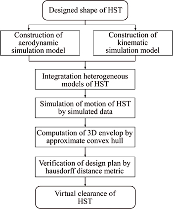
Fig. 2 Flowchart of virtual clearance computation method
3 Simulation model construction
3.1 Aerodynamic simulation model construction
Usually, the running speed of an HST is lower than 450 km/h, and the flow field around the train can be simulated with incompressible flow models. The three-dimensional aerodynamic simulation method is used to analyze the performance of the HST running under crosswind, and its flow field can be considered a transient viscous turbulent flow. Therefore, the Navier�CStokes equations for impressible flow along with k�C�� equations are adopted for the physical performance analysis, which can be written as [18, 19]
 (1)
(1)
where t is the time; �� is the density of the air; u is the velocity of the air; ��t is the eddy viscosity; Eij is the rate of deformation; ��k, ����, C1��, C2�� are adjustable constants obtained by numerous iterations of data fitting for a wide range of turbulent flows. The commercial CFD solver FLUENT is used to solve Eq. (1), and the standard values of k�C�� model parameters available in the software are used. The aerodynamic forces such as the drag force, the lift force and the side force are then calculated, which are set as the output forces for the kinematic simulation of the HST.
3.2 Kinematic simulation model construction
The train track coupling system mainly includes the vehicle dynamics, the track dynamics, and the wheel�Crail contact. Usually, an HST is modeled with rigid components of the vehicle body, bogie and wheel-set connected by springs and dampers, and the elastic deformation of the components is neglected. Assuming that the speed of the HST is constant and is constrained in the longitudinal direction, the equations of the train�Ctrack coupling dynamic system can be written as [20, 21]
 (2)
(2)
where M, D, and K are the mass, damp, and stiffness matrixes of the train�Ctrack system, respectively; X,  and
and  are the generalized displacement, velocity, and acceleration of the system, respectively; F is the generalized load force including the rail excitation and the aerodynamic force. The commercial software program SIMPACK is used to solve Eq. (2), and the mass, damping, and stiffness parameters are set according to the type of the HST.
4 Virtual 3D clearance computation
4.1 Heterogeneous model integration
The detail design plan for an HST is usually created by 3D modeling software along with boundary representation. However, the aerodynamic model is created with hexagonal elements involved in the space of the surfaces and the air boundaries, and the kinematic model is represented with a simplified geometry model. Even worse, those models are distributed in different software programs, such as Solidworks, Pro/E, Catia, SIMPACK, Adams, Fluent, and Start-ccm+. Therefore, the design model and the simulation models consist of heterogeneous models, and it is difficult to integrate those models and compute the virtual clearance of the HST according to the geometry model and the simulated physical properties. We extract the surface model of the HST from the designed 3D model and the aerodynamic simulation model separately. The physical properties of the HST for kinematic simulation such as the displacement and velocity in the global coordinate system are then exported. This describes the motion of the HST in difference directions. Finally, a data struct containing both the extracted surface model and the dynamic physical properties is created to represent the integrated heterogeneous HST model. Based on the new data struct, the physical motion of the HST is simulated effectively, and the virtual clearance of the HST is computed efficiently.
4.2 Physical motion simulation
In the new data struct for the virtual clearance computation of the HST, the geometry model consists of the outside surface of the HST, and it is aligned with the position of the HST in the global coordinate system for kinematic simulation. The arrays containing both the displacement and the velocity are then adopted to drive the surface model of the HST to simulate the physical motion. The new data struct also contains an array of time steps that has the same number of members as the displacement and the velocity. The velocity and displacement of the HST consist of both the translation and the rotation in the X, Y and Z directions. Therefore, the average velocities including the linear and angular velocities are described as 


 and
and
 and
and  , respectively. The transformation matrix of the HST in each time step can then be represented as
 (3)
(3)
where Tx, Ty, Tz are the translation parts of the transformation matrix; which can be computed as follows:


and Rx, Ry, Rz are the rotation parts of the transformation matrix, which are represented as
 ,
,
 ,
,
 .
.
In the simulation of physical motion of an HST, the transformation matrix is applied to pre-multiply the previous one to obtain a new position in the global coordinate system, which is computed as
 (4)
(4)
The position of the HST at each time step during the physical motion simulation is obtained by applying the transformation matrix consistently according to Eq. (4), and these data are then used to compute the virtual clearance effectively. Therefore, a timer is used to trigger the transformation of the geometry model of the HST with a constant time interval, and the physical motion of the HST is shown in a series of animations.
4.3 3D envelope computation
The physical motion of the HST can be simulated and visualized effectively with the method described above. However, it is difficult to exactly compute the geometric 3D envelope of the HST moving along a track in the physical world. The 3D envelope of the moving HST is the key factor in the computation of the clearance. Therefore, the well-known geometric object called the convex hull is utilized to approximate the 3D envelope.
4.3.1 Brief review of convex hull
Let  be a finite point set in space. A convex combination can be expressed as a linear combination of each point
  and its assigned weight ��i, which is nonnegative and sums to one. For each choice of weights, the resulting convex combination is a point in the convex hull, and the whole convex hull can be formed by choosing coefficients in all possible ways, which can be formulated as follows:
 (5)
(5)
The convex hull of a finite point set  denoted by CH(P), is the smallest convex polyhedral that encloses all points in the set. It is a sequence of points such as
  where h��n and
  for j=1, 2, ��, h. Figure 3 shows a set of points and its convex hull.
Many studies have been conducted on the calculation of the convex hull in a plane, some of which can be extended to a higher dimension. The naive algorithm for computing the convex hull is to find extreme points that lie on the convex hull by iteratively testing all pairs of points, which runs in more than O(n2) times. Because the order of the point in the set plays an important role in the computation of the convex hull, many researchers have proposed effective methods to reduce the sorting problem to the convex hull computation, and it is proved that all of these methods that compute the convex hull of n points belong to O(nlgn) [22�C26]. An elegant method for optimal output sensitive construction of a convex hull is proposed by combining the Graham scan algorithm [23] with Jarvis march [22], which obtains an optimal O(nlgh) time, where h denotes the number of points [27].

Fig. 3 An example of convex hull in plane
4.3.2 Convex hull based envelope approximation
According to Section 4.2, the discrete surface model of an HST is driven to simulate the motion in the physical world by using the simulated kinematic data series. The points contained in the discrete surface model usually number more than the hundreds of thousands, and the time steps also number more than thousands, denoted by m. Obviously, the envelope approximation of the HST can be constructed by fusing the discrete surface model of each time step first and then approximating the convex hull of the fused data by using Chan��s algorithm [27], which obtains an optimal O(n��mlgh) time. However, significant memory and computation costs are incurred by approximating the convex hull of the fused data.
Because the transformation of the HST at each time step is rigid, the convex hull of the original model should also transform rigidly. Therefore, the transformation- based convex hull approximation method is adopted to compute the envelope of the HST effectively and efficiently. It mainly contains three steps: 1) Compute the convex hull of the original HST model. Chan��s algorithm is used to compute the convex hull of the original model, denoted by S=CH(P), which takes O(nlghs) time, where hs is the number of points contained in the convex hull of the original model. 2) Transform the convex hull continually. According to the transformation matrix of the HST for the motion simulation in the physical world, the convex hull is also transformed at each time, constructing m subsets  for i=1, 2, ��, m. 3) Approximate the 3D envelope of the HST. The set of the convex hull is involved in the computation of the envelope of the HST by executing Jarvis��s march algorithm [22], which takes O(mlghs) time. The total time cost of the proposed method is O(mlghs+nlghs), which is much less than that using Chan��s algorithm [27] to compute the convex hull of the fused dataset. The memory cost of this method is also linear with the number of points in the convex hull of the original model. It is also much less than that incurred by directly fusing the discrete model.
4.4 Shape design plan verification
According to the national standards, the profile indicating the minimum standard clearance for an HST is extruded along the moving direction when constructing a 3D surface model. The Hausdorff metric is then used to measure the distance of the 3D envelope of the moving HST from the standard model. We set the 3D envelope surface model and the standard model as X, Y, respectively. The Hausdorff distance dH(X, Y) is defined by [28]
 (6)
(6)
where sup represents the supremum and inf is the infimum; d(x, y) denotes the distance between points x and y. The sign of the distance is also involved in the Hausdorff metric to denote whether a point on the envelope surface lies inside or outside the surface of the standard models. Therefore, it can be represented as follows:

 (7)
(7)
where sgn defines the sign function, and ny is the normal of point y. A color map of the Hausdorff distance is created to verify that the designed shape of the HST meets the national standards. The negative distance and positive distance are colored with different colors, and the interval changes gradually. The negative value of the surface indicates that points in this part are outside the standard model, which means that the designed shape of the HST does not meet the national standards. Therefore, the proposed method provides an easy and obvious way to verify that the designed shape of the HST meets the national standards.
5 Experiment and application
The model integration and convex hull-based virtual clearance computation method proposed in this work has been implemented in the Visual C++ 2008 environment. The shape of CRH380B is taken as an example to illustrate how to use the proposed method to verify that the clearance meets the national standards in the design phase. The example runs on a PC with a 2.50 GHz CPU (Intel Core i5-2450M) and 4 GB of RAM. In the application of the proposed model, the physical properties of the key components such as the size, weight, center and moment are computed, and the simplified geometry model is created to represent the wheel, track, springs and dampers for dynamic analysis of the HST. The related physical properties are then set via SIMPACK. The kinematic simulation model is shown in Fig. 4. With regard to the aerodynamic property analysis, the outside surface of the HST is created according to the detail design plan, and the air walls for the simulation are also created. The volume between them is then meshed with hexagonal elements via the Gambit software program. The parameters for impressible turbulence aerodynamic simulation of the HST are set, and the physical properties are simulated via FLUENT. The simulation model of the aerodynamic analysis is shown in Fig. 5. Based on the simulation model, the physical properties for kinematic and aerodynamic analysis are checked to meet the requirements.

Fig. 4 Simulation model for kinematic analysis

Fig. 5 Simulation model for aerodynamic analysis
After the physical properties are checked, the surface model of the middle body of the HST is extracted. The number of points in the extracted surface model is 51341, and the number of faces is 94167. The surface model is colored with grey, and its wireframe representation is colored with red, as shown in Fig. 6. The kinematic physical properties such as the displacement and velocity of the HST in the X, Y and Z directions are then exported from SIMPACK. The plot of the velocity and the angular velocity in the X, Y and Z directions is shown in Fig. 7. This shows that the HST runs at a constant speed of approximately 200 km/h, vibrates in the Y and Z directions and rotates in X, Y and Z directions. The simulated data contain 1000 time steps, and the time interval is 0.03 s. Based on the kinematic physical properties, a timer is used to drive the surface model transform in the global coordinate system continuously. Thus, the physical motion of the HST is simulated effectively.
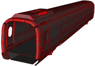
Fig. 6 Extracted surface model of HST
The X-component of the velocity is neglected in the computation of the envelope of the HST. If the extracted surface is fused together, it will contain more than 50��106 points. When the conventional methods are used to compute the convex hull of the fused data, it is difficult for a personal computer to meet the requirements for memory and computation. However, the proposed method can compute the envelope efficiently. To obviously visualize the relationship between the original model of the HST and its convex hull, they are aligned together in the global coordinate system, as shown in Fig. 8. The wireframe representation of the HST is colored in green, and its convex hull is colored in red with 50% opacity to obviously show the difference between them. The convex hull of the original model contains 105 points, which is much fewer than the original model. The transformation matrix is then used to drive the convex hull of the original model to move according to the kinematic properties at each time point. They consist of a set of convex hulls, and the rightmost position, upmost position, leftmost position, and original model are colored in blue, purple, green and yellow, respectively, as shown in Fig. 9. Finally, the envelope of the HST is computed efficiently by the proposed method, as shown in Fig. 10. The total time cost of the proposed method is 1088 ms, and the time taken by Chan��s algorithm on the fused model is more than 402165 ms.
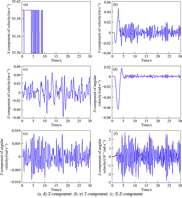
Fig. 7 Velocity (a, b, c) and angular velocity (d, e, f) of HST:

Fig. 8 Original HST model and its convex hull (The HST is colored in green, and its convex hull is colored in red with 50% opacity)
The proposed method is almost 400 times faster than the conventional method, and the memory consumption of the proposed method is also reduced by approximately 90%. The results show that the proposed method can be used to compute the envelope of the HST efficiently and effectively.

Fig. 9 Combination of convex hull of moving HST (the leftmost position, the upmost position, the rightmost position, and the original model are colored in blue, purple, green and yellow, respectively)

Fig. 10 Envelope of moving HST
A timer with constant intervals is used to trigger the extracted surface to simulate the physical world motion. A combination of the extracted surface model represented by the wireframe and the convex hull with 50% opacity is used to obviously show the relationship between them. The extracted surface model is then driven to move according to the kinematic properties in the global coordinate system at each time step. Frames of the animation at times 0.0, 1.2, 2.8 and 6 s are shown in Fig. 11. The result shows that the envelope computed by the proposed method is correct. This provides an easy way to verify the accuracy of the envelope computation.
Finally, the standard model is created by extruding the profile indicating the minimum standard clearance of the HST along the moving direction, as shown in Fig. 12. The standard model and the envelope of the HST are then aligned in the global coordinate system, and the Hausdorff metric is used to measure their distance from each other. A combination of the standard model and the envelope is used to display the position relationship, and a color map and a legend are used to visualize the distance, as shown in Fig. 13. The minimum of the Hausdorff distance is colored in blue and the maximum in red, and the interval changes gradually. The upper- right and bottom-left part of the envelope are colored in blue, and the distance value is 0.0733 m, which meets the requirement according to the national standard. This shows that the proposed method can be used to verify that the shape design plan of the HST meets the requirement easily and obviously. If the design plane does not meet the requirement, the distance can also be used to guide the modification of the design plan, and the procedure shown in Fig. 1 is run iteratively until the clearance meets the national standards. It can be found that the virtual clearance of the HST is also checked in the design phase easily and effectively, in addition to the kinematic and aerodynamic properties. This greatly reduces the number of prototypes required to be built compared with the conventional methods.
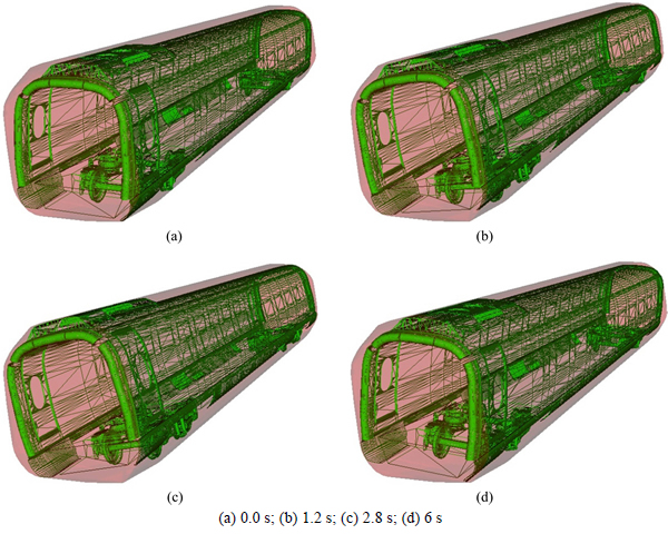
Fig. 11 Animation frames of moving HST at time:
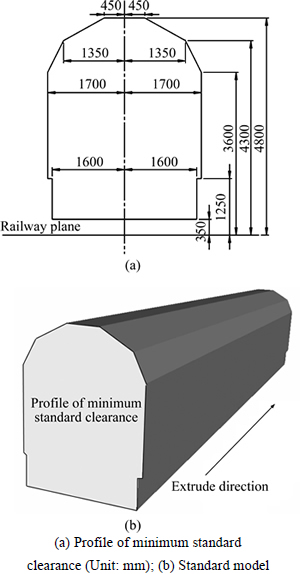
Fig. 12 Standard model constructed by extruding profile of minimum standard clearance (the solid black line shows the profile of the minimum standard clearance, and the red arrow shows the extrusion direction):
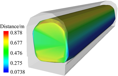
Fig. 13 An illustration of Hausdorff distance between standard model and envelope (the envelope of the HST is shown with a color map, and the surface model is 50% opaque)
6 Conclusions and future works
A new method for approximating the clearance of an HST in the design phase was proposed. Both the kinematic and aerodynamic properties were checked according to requirements, and the kinematic properties were then used to drive the design model to simulate motion in the physical world. The envelope of the moving train was obtained by the approximate convex hull method efficiently and effectively. The shape design plan is verified to meet the national standards by using the Hausdorff distance, and a color map is used to obviously visualize the final result. The proposed method provides an easy and effective way to add the clearance inspection procedure into the design and analysis procedure of the HST, which will greatly reduce manpower and material resource consumption. This is of practical significance for speeding up the design of HSTs or similar railway vehicles such as locomotives, mass transit vehicles, and bi-level trains.
References
[1] SCHEWE H, HOLL J, GRUNDIG L. LIMEZ-photogrammetric measurement of railroad clearance obstacles [C]// Third Turkish- German Joint Geodetic Days. Istanbul, Turkey: Towards a Digital Age, Volume II, 1999: 721�C727.
[2] CHEN Zhi-yong, HU Qing-wu, GUO Sheng, YUAN Jian-feng. Application of L-MMS in railroad clearance detection [C]// The 5th International Symposium on Mobile Mapping Technology. 2007: 61�C65.
[3] LIU Yu, SHI Hong-mei, ZHU Li-qiang, XU Xi-ning. Research and design of railway clearance measurement system based on non- contact sensors [C]// Proceedings of the 8th World Congress on Intelligent Control and Automation. 2010: 6883�C6886.
[4] KOHUT P, MIKRUT S, PYKA K, TOKARZYK R, UHL T. Research on the prototype of rail clearance measurement system [C]// International Archives of the Photogrammetry, Remote Sensing and Spatial Information Sciences. 2012: 385�C389.
[5] ZHAN Dong, YU Long, XIAO Jian, CHEN Tang-long. Multi- camera and structured-light vision system (MSVS) for dynamic high-accuracy 3D measurements of railway tunnels [J]. Sensors, 2015, 15(4): 8664�C8684.
[6] POMBO J, AMBROSIO J. General spatial curve joint for rail guided vehicles: Kinematics and dynamics [J]. Multibody Systems Dynamics, 2003, 9: 237�C264.
[7] KASSA E, ANDERSSON C, NIELSEN J. Simulation of dynamic interaction between train and railway turnout [J]. Vehicle System Dynamics, 2006, 44: 247�C258.
[8] LEI Xiao-yan, MAO Li-jun. Dynamic response analyses of vehicle and track coupled system on track transition of conventional high speed railway [J]. Journal of Sound and Vibration, 2004, 271(3�C5): 1133�C1146.
[9] POMBO J, AMBROSIO J. Modelling tracks for roller coaster dynamics [J]. International Journal of Vehicle Design, 2007, 45: 470�C500.
[10] LING Liang, XIAO Xin-biao, XIONG Jia-yang, ZHOU Li, WEN Ze-feng, JIN Xue-song. A 3D model for coupling dynamics analysis of high-speed train/track system [J]. Journal of Zhejiang Univrsity: Science A(Applied Physics& Engineering), 2014, 15(12): 964�C983.
[11] YANG Xin-wen, GU Shao-jie., ZHOU Shun-hua, YANG Jian-jin, ZHOU Yu, LIAN Song-liang. Effect of track irregularity on the dynamic response of a slab track under a high-speed train based on the composite track element method [J]. Applied Acoustics, 2015, 99: 72�C84.
[12] YAO Shuan-bao, GUO Di-long, SUN Zhen-xu, YANG Guo-wei, CHEN Da-wei. Optimization design for aerodynamic elements of high speed trains [J]. Computers & Fluids, 2014, 95: 56�C73.
[13] YANG Xin-wen, JIN Jie-long, SHI Guang-tian. Preliminary study on streamlined design of longitudinal profile of high-speed train head shape [C]// 13th COTA International Conference of Transportation Professional. 2013: 1469�C1476.
[14] BAKER C. The flow around high speed trains [J]. Journal of Wind Engineering and Industrial Aerodynamics, 2010, 98(6, 7): 277�C298.
[15] HEMIDA H., KRAJNOVIC S. LES study of the influence of the nose shape and yaw angles on flow structures around trains [J]. Journal of Wind Engineering and Industrial Aerodynamics, 2010, 98(1): 34�C46.
[16] BELL J R, BURTON D, THOMPSON M C, HERBST A H, SHERIDAN J. Moving model analysis of the slipstream and wake of a high-speed train [J]. Journal of Wind Engineering and Industrial Aerodynamics, 2015, 136: 127�C137.
[17] YAO Shuan-bao, GUO Di-long, SUN Zhen-xu, YANG Guo-wei, CHEN Da-wei. Optimization design for aerodynamic elements of high speed trains [J]. Computers & Fluids, 2014, 95: 56�C73.
[18] ABSI R. Analytical solutions for the modeled k equation [J]. Journal of Applied Mechanics, 2008, 75(4): 044501.
[19] LAUNDER B E, SPALDING D B. The numerical computation of turbulent flows [J]. Computer Methods in Applied Mechanics and Engineering, 1974, 3(2): 269�C289.
[20] ZHAI W M, CAI C B, GUO S Z. Coupling model of vertical and lateral vehicle/track interactions [J]. Vehicle System Dynamics, 1996, 26(1): 61�C79.
[21] AMBROSIO J. Train kinematics for the design of railway vehicle components [J]. Mechanism and Machine Theory, 2010, 45(8): 1035�C1049.
[22] JARVIS R A. On the identification of the convex hull of a finite set of points in the plane [J]. Information Processing Letters, 1973, 2: 18�C21.
[23] GRAHAM R L. An efficient algorithm for determing the convex hull of a finite planar set [J]. Information Processing Letters, 1972, 1: 132�C133.
[24] ANDREW A M. Another efficient algorithm for convex hulls in two dimensions [J]. Information Processing Letters, 1979, 9(5): 216�C219.
[25] KIRKPATRICK D G, SEIDEL R. The ultimate planar convex hull algorithm [J]. SIAM Journal on Computing, 1986, 15(1): 287�C299.
[26] BARBER C B, DOBKIN D P, HUHDANPAA H. The quickhull algorithm for convex hulls [J]. ACM Transactions on Mathematical Software, 1996, 22(4): 469�C483.
[27] CHAN T M. Optimal output-sensitive convex hull algorithms in two and three dimensions [J]. Discrete and Computational Geometry, 1996, 16: 361�C368.
[28] CIGNONI P, ROCCHINI C, SCOPIGNO R. Metro: Measuring error on simplified surfaces [J]. Computer Graphics Forum, 1998, 17(2): 167�C174.
(Edited by YANG Hua)
Cite this article as:
YI Bing, LI Xiong-bing, ZENG Wei, SONG Yong-feng, YANG Yue. A novel method for virtual clearance computation of high-speed train based on model integration and convex hull [J]. Journal of Central South University, 2017, 24(10): 2458�C2467.
DOI:https://dx.doi.org/https://doi.org/10.1007/s11771-017-3657-8Foundation item: Projects(51605495, 51575541) supported by the National Natural Science Foundation of China; Project(2015JJ2168) supported by the Natural Science Foundation of Hunan Province of China
Received date: 2016-02-22; Accepted date: 2016-12-30
Corresponding author: YI Bing, PhD, Assistant Professor; E-mail: bingyi@csu.edu.cn
Abstract: The 3D clearance of a high-speed train (HST) is critical to ensure the safety of railway transportation. Many studies have been conducted on the inspection of the clearance profile in railway operation based on the vision system, but few researchers have focused on the computation of the 3D clearance in the design phase of an HST. This paper summarizes the virtual 3D clearance computation of an HST based on model integration and the convex hull method. First, both the aerodynamic and kinetic analysis models of the HST are constructed. The two models are then integrated according to the corresponding relationship map, and an array of transformation matrixes of the HST is created to drive the designed model simulating the physical railway motion. Furthermore, the convex hull method is adopted to compute the 3D envelope of the moving train. Finally, the Hausdorff metric is involved in the measurement of the minimum clearance model and the 3D envelope model. In addition, the color map of the Hausdorff distance is established to verify that the designed shape of the HST meets the national standards. This paper provides an effective method to accurately calculate the 3D clearance for the shape design of an HST, which greatly reduces the development cost by minimizing the physical prototype that must be built.
