
J. Cent. South Univ. (2016) 23: 841-849
DOI: 10.1007/s11771-016-3131-z

A novel current vector decomposition controller design for six-phase permanent magnet synchronous motor
YUAN Lei(Ԭ��), HU Bing-xin(������), WEI Ke-yin(κ����), LIN Ying(��Ө)
Institute of Communications Engineering, PLA University of Science and Technology University, Nanjing 210007, China
 Central South University Press and Springer-Verlag Berlin Heidelberg 2016
Abstract:
The vector control algorithm based on vector space decomposition (VSD) transformation method has a more flexible control freedom, which can control the fundamental and harmonic subspace separately. To this end, a current vector decoupling control algorithm for six-phase permanent magnet synchronous motor (PMSM) is designed. Using the proposed synchronous rotating coordinate transformation matrix, the fundamental and harmonic components in d-q subspace are changed into direct current (DC) component, only using the traditional proportional integral (PI) controller can meet the non-static difference adjustment, and the controller parameter design method is given by employing internal model principle. In addition, in order to remove the 5th and 7th harmonic components of stator current, the current PI controller parallel with resonant controller is employed in x-y subspace to realize the specific harmonic component compensation. Simulation results verify the effectiveness of current decoupling vector controller.
Key words:
six-phase PMSM; current vector decomposition; internal control; resonant control��
1 Introduction
Using the vector space decomposition approach, the currents in a multiphase machine with distributed winding can be decoupled into the flux and torque producing ��-�� components, and the loss-producing x-y and zero-sequence components [1-2]. Due to the existence of additional degrees of freedom, controlling only ��-�� currents produced by torque and flux is insufficient and additional controllers are necessary to nullify the x-y currents that may flow due to the machine or converter asymmetry [3]. Compared with three-phase machine, some problems of six-phase machines (having two sets of three-phase windings spatially shifted by 30 electrical degrees) are not encountered with conventional three-phase drives. A good example is the challenging feature of easily occurring large stator current harmonics [4-5]. The reason for this major drawback is that the stator current harmonics of the order (6k��1, k=1, 3, 5��), especially 5th and 7th current harmonics, are limited only by the very small stator leakage impedance [6-7]. Moreover, two three-phase winding sets have inherent asymmetries [8], stator current sharing will be unbalanced if there are not any measures. Especially, for the six-phase permanent magnet synchronous machine (PMSM), permanent magnets may not produce pure sinusoidal flux distribution, and rotor saliency, pole shape and possible magnetic saturation can cause harmonics in the air-gap flux [9]. These non-idealities can be a major problem in six-phase PMSM because they can easily produce large internally generated current harmonics.
In order to eliminate the stator current unbalance, various control schemes for six-phase machines have been suggested in literatures. One approach for modeling and control is a double d-q winding representation [10-14]. This approach replaces both three-phase winding sets with equivalent d-q windings, which controls the two sets of windings separately. The two individual current controllers in the double synchronous reference frames share the same current reference from a speed controller. Although this method can provide excellent performance for current unbalance compensation between two sets, it cannot compensate the current unbalance between phase windings in each set. Meanwhile, there are mutual coupling voltages between two sets of three-phase windings, which is hard to compensate completely, and hence, its dynamic torque performance may be affected. Meanwhile, the 5th and 7th current harmonics are only suppressed to some extent due to the limited bandwidth of PI control.
An alternative modeling and control approach is the VSD based vector control method [4, 9, 15-16] as presented in Ref. [1] based on the conventional VSD current control, of which two individual current PI regulators are used for current unbalance compensation. This method could provide excellent dynamic torque performance without the influence of coupling voltages between two sets. Moreover, under ideal sinusoidal supply conditions, the source would be able to supply the machine with fundamental voltage component only. This would mean that the x-y plane cannot be excited, provided that the machine is perfectly symmetrical. However, if there is any asymmetry between the two three-phase stator windings, even sinusoidal supply of the machine leads to not only stator current flow in the d-q plane but also appearance of stator currents of fundamental frequency in the x-y plane since the problem of unbalanced current sharing between the three-phase windings appears. So the current unbalance can also be compensated by minimizing the currents in x-y plane to be zero, but the current unbalance between phase windings in each set as well as the 5th and 7th current harmonics are not taken into account.
In this work, a six-phase PMSM and the inverter arrangement are illustrated, two separate DC powers (PWM rectifier) are used to supply the two three-phase windings respectively. Compared with multiphase inverter with same DC link, a potential unbalance current sharing will occur easily [14] when the separated DC links have some difference. In addition, the influence of the non- sinusoidal back electromotive force (EMF) of PMSM and inverter non-linearity, which will also generate the 5th and 7th current harmonics components. In order to solve the above problems, a new current vector decomposition control is proposed for the current unbalance and the 5th and 7th current harmonics. The effectiveness of proposed method is finally verified by a set of comparative simulation and experiment results.
2 Mathematical model of six-phase PMSM
As shown in Fig. 1, the six-phase PMSM presented has two sets of three-phase stator windings spatially shifted by 30 electrical degrees with isolated neutral points (A, B and C is the first set of winding, and U, V and W is another one). Moreover, to ensure each three-phase winding has the same DC voltage, the sets of winding is supplied by the same PWM rectifier respectively. Moreover, coordinates in this paper are defined in Fig. 2, the ��-�� frame is defined as the stationary reference frame, and the d-q frame is defined as the rotating reference frame.
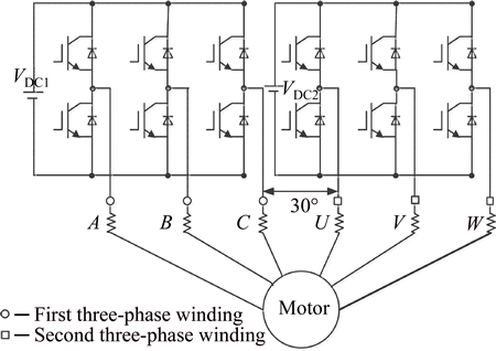
Fig. 1 Six-phase PMSM drive system

Fig. 2 Coordinates of six-phase PMSM based VSD method
Using VSD method [1], the machine six-phase variables can be transformed into stationary reference quantities, which appear in three mutually orthogonal planes, such as ��-�� plane, x-y plane and zero-sequence plane. The torque and flux producing fundamental component and the 12k��1th, k=1, 2, 3�� harmonics are mapped into ��-�� plane, while the loss-producing 6k��1th, k=1, 3, 5�� harmonics, including the 5th and 7th harmonics, are mapped into x-y plane. Zero-sequence components have been omitted because zero-sequence current cannot flow due to the isolated neutrals. For six-phase PMSM, the amplitude invariant transformation matrix used by Fig. 2 is given as
 (1)
(1)
A rotational transformation is applied to transform a ��-�� variables into a synchronously rotating reference, which is suitable for vector control as
 (2)
(2)
The transformation of d-q plane variables in Eq. (2) is identical as in the case of a three-phase system. The second pair of variables x-y plane is not rotationally transformed since the equations for these variables do not contribute to the electromagnetic torque and hence electromechanical energy conversion.
Using VSD model method, the voltage equations of six-phase PMSM in synchronously rotating reference are as followings:
 (3)
(3)
 (4)
(4)
where R is the stator resistance; Lx(x=d, q) is the stator inductances; Lz is the leakage inductance; ux(x=d, q, x and y) is the stator voltage component; ix(x=d, q, x and y) is the stator current component and ��e is the electrical angular speed; ��f is the permanent magnet flux; d/dt is the differential operator.
3 Current unbalance compensation analysis
As previously analyzed, the six-phase PMSM drive system shown in Fig. 1 can cause a potential unbalance current sharing easily, and the actual experiment current wave used by the traditional vector control method as three-phase machine is presented in Fig. 3, from the experiment result we can see that the two sets of wingdings exist serious current unbalance (asymmetry) phenomenon and a lot of harmonic components.
To compensate the current phenomenon, assume that the currents in the first winding (A, B and C) are balanced as

Fig. 3 Stator current experiment curve of traditional current vector control scheme
 (5)
(5)
While the amplitude of phase currents in the other winding (U, V and W) differs by arbitrary factors m and n as
 (6)
(6)
Using the invariant transformation matrix (1), the current components in x-y plane can be obtained by
 (7)
(7)
where  .
.
From Eq. (7), it can be seen that there are fundamental currents in x-y plane, which is in accordance with Ref. [8], and it is the reason for the phase current unbalance phenomena.
In order to obtain better control effect, a new synchronous rotating coordinate matrix is proposed as
 (8)
(8)
Using Eqs. (7) and (8), and the currents in dx-dy plane are given by
 (9)
(9)
Note that the coefficient k1 now directly determines the double-frequency components. If the arbitrary factors satisfy m=n, the AC component will disappear, and this is in contrast to Eq. (7). The current unbalance between windings will appear as a DC component, and will be easily compensated using PI controllers.
4 Current harmonics compensation analysis
In fact, using VSD transformation method, only per phase current of six-phase PMSM is completely symmetric, (6k��1)th, k=1, 3, 5 �� harmonics, including the 5th and 7th harmonics, can be mapped into x-y plane. There are two main sources for stator current harmonics. The first source is the inverter non-linearity, which can cause large stator current harmonics if the supplied voltage contains harmonic components of the order (6k��1, k=1, 3, 5 ��). The second one is the structure of PMSM itself, permanent magnets may produce non- sinusoidal back EMF and rotor saliency, pole shape and possible magnetic saturation can cause harmonics in the air-gap flux.
Considering the non-sinusoidal back EMF and inverter non-linearity, the 5th and 7th current harmonics in phase currents are inevitable, in order to reduce the current total harmonic distortion and increase efficiency, they should be eliminated. Assuming the 5th and 7th harmonics in the phase current, voltage or flux can be expressed as
 (10)
(10)
 (11)
(11)
where I1, I5 and I7 are the amplitude of fundamental component, 5th harmonic component and 7th harmonic component, respectively.
For control purposes, it is more useful to have the control variables in the d-q synchronous reference frame. For the d-q model, currents in the synchronously rotating frame are given as
 (12)
(12)
By applying Eqs. (6) and (7) to (8), the following relationship can be obtained as
 (13)
(13)
 (14)
(14)
By using the new synchronous rotating coordinate matrix (7), from Eq. (9), it can be seen that the fundamental components in d-q plane appear as DC quantities and can hence be easily dealt with using PI controllers. From Eq. (10), the 5th and 7th harmonics in x-y plane are converted to 6th harmonics in dx-dy plane, it can be seen that by suppressing the 6th current harmonics in dx-dy plane, the 6th current harmonics in x-y plane for each set can be suppressed simultaneously. Consequently, the 5th and 7th current harmonics in each phase can be suppressed simultaneously.
5 Current vector decomposition controller design
As mentioned above, by using VSD transformation method, the fundamental component and different order harmonic components of six-phase PMSM can be transformed into mutually orthogonal planes, and the current controllers in different planes can be designed respectively, which will achieve completely decouple control. Starting from this consideration, the proposed current control scheme is divided into two parts, including four independent current components, as depicted in Fig. 4.
1) The first part controls the d-q current components in d-q plane, where flux and torque production of machine is controlled. The current reference iq* is from the output of the speed controller, and the current reference id* is set to be id*=0.
2) The second part controls the dx-dy current components in dx-dy plane. Since these components should be zeroed, the reference values at the input of the current controllers are set to zero, i.e.,  and
and  aiming for current unbalance and the 5th and 7th current harmonics compensation in x-y plane.
5.1 Current controller in d-q plane
By employing the transformation matrix (8), the control variables in the d�Cq plane appear as DC quantities and can hence be easily dealt using PI controllers. Performance of a simple PI controller based current control can be greatly improved by eliminating the cross coupling effects in the stator voltage equations. This decoupling procedure requires that the following decoupling voltage terms are added to the output of the current controllers
 (15)
(15)
Decoupling can be done by feeding the decoupling terms (15) as positive feedback (measured quantities are used to calculate the decoupling voltage terms) or as feedforward (reference values are used to calculate the decoupling voltage terms) to the output of the current controllers. In both approaches, the system should behave from the perspective of the current control like two independent linear first-order systems, thus simplifying the design of the current controllers.
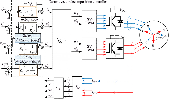
Fig. 4 Current decomposition vector control diagram of six-phase PMSM system
Based on the machine model, the decoupled system in the d-q reference frame has transfer function
 (16)
(16)
Assuming that Eq. (16) adequately describes the behavior of the system and machine parameters are accurate, current controller parameters can be easily designed to give the desired closed loop response. The model based method in Ref. [17] is used here. Parameters for the d-q plane PI current controllers are calculated from
 (17)
(17)
and the reference voltage in d-q plane can be calculated as
 (18)
(18)
where Kd,q is the proportional gain and Tid,q is the integral time constant.
In summary, the control block diagram in d-q plane can be shown in Fig. 5.

Fig. 5 Current vector control diagram in d-q plane
5.2 Current controller in dx-dy plane
By using the new synchronous rotating coordinate matrix (7), the 5th and 7th harmonics in x-y plane are converted to the 6th harmonic in dx-dy plane. However, due to the bandwidth limitation of the PI controller, the PI controller is incapable of eliminating AC signal error. To obtain zero steady-state error with tracking AC signal, the resonant controller can track AC signal reference with zero steady-state error for sinusoidal inputs with the same frequency as its resonant frequency. So a modified PI controller with resonant controller will be proposed in this work, which will eliminate current unbalance and the 5th and 7th current harmonics.
An ideal resonant controller can be expressed in the s-domain as in Refs. [18-19]:
 (19)
(19)
where ��0 is the resonant frequency, and KI is the proportional gain. When the frequency of AC signal is ��0, i.e., s=j��0, and the amplitude can be obtained as
 (20)
(20)
From Eq. (20), it can be seen that the amplitude of GR(s) will become infinite, which obtain zero steady- state error for sinusoidal inputs with the same frequency as its resonant frequency. However, the ideal resonant controller Eq. (19) exists an implementation problem in practical application, so an improved quasi-resonant controller is employed in this work, the transfer function is expressed as [20]
 (21)
(21)
where ��c is the cut-off frequency. From Eq. (21), it can be seen that the resonant controller contains two variables, the parameter KI will be adjusted to eliminate the steady-state error, and the parameter ��c will be regulated to inhibit the effect of frequency fluctuation.
In summary, the control block diagram in dx-dy plane can be shown in Fig. 6.
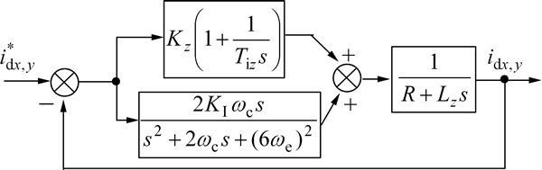
Fig. 6 Current vector control diagram in dx-dy plane
6 Simulation and experiment results analysis
6.1 Simulation results analysis
Performance of the suggested control scheme is first analyzed using Matlab/Simulink soft according to the proposed control diagram as shown in Fig. 3. The motor parameters are presented as [21]: rate power P=2180 kW, rate voltage U=690 V, rate current i=981��2 A, number of pole pairs p=30, rotor inertia J= 16000 kg��m2, rate speed Nr=17 r/min, d-axis inductance Ld=4 mH, q-axis inductance Lq=5 mH, stator resistance R=0.0192 ��.
In order to compare with the traditional vector control scheme, Fig. 7 shows the simulation results of the traditional technology firstly. The current controllers for dx-dy plane current components are not used, only considering the flux and torque producing d-q components. From Fig. 7, stator current ix contains much more current harmonic components and the current amplitude is also big, due to the dx-dy plane current components are not considered, i.e., the reference voltages of dx-dy plane is set to be ux*=uy*=0. From the FFT analysis results of the phase current, the 5th harmonic content is 18.32%, 7th harmonic content is 14.33%, and the total harmonic (THD, Dth) is 23.45%.

Fig. 7 Simulation results of traditional current control algorithm:
In contrast, when the proposed control method with considering dx-dy plane current components are employed, Fig. 8 gives the detail simulation results. It can be seen that the current harmonic components and current amplitude of the stator current ix are suppressed effectively, and the phase currents keep balance. Moreover, from the FFT analysis results, the 5th harmonic content is 0.29%, 7th harmonic content is 0.13%, and the total harmonic THD is 3.73%. Compared with the traditional control scheme, the presented technology in this work has better control performance.
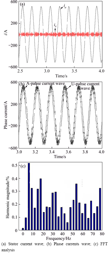
Fig. 8 Simulation results of proposed current control algorithm:
6.2 Experiment results analysis
To demonstrate the effectiveness of the proposed current control scheme, keep the stator current three-phase sets balanced and eliminate the current harmonic component, the drive operation is examined at experiment platform.
According to the preceding analysis conclusions, due to the unbalanced current sharing between the three-phase windings and inverter non-linearity, stator currents of fundamental frequency in the x-y plane appear. In order to eliminate the fundamental frequency component, a PI controller is employed in dx-dy plane, and the reference currents  and
and are set to be
  And Fig. 9(a) shows the experiment results based on current PI controller used in dx-dy plane, it can be seen that the current unbalance problem has some improvement, but there is still a slight unbalance. Due to the bandwidth limitation of the PI controller, the PI controller is incapable of eliminating AC signal error. Moreover, it can be also seen from Fig. 9(b) that phase current of the machine contains a lot of current harmonic components, especially the 5th and 7th harmonic components.
To eliminate the 5th and 7th harmonic components, a modified PI controller with resonant controller is used,and the reference currents and idy is set to be  Moreover, from the foregoing analysis, the 5th and 7th current harmonics in x-y plane are converted to 6th harmonic in dx-dy plane by employing the proposed synchronous rotating coordinate matrix, and the 5th and 7th current harmonics will be eliminated simultaneously when the cut-off frequency ��c of resonant controller is set to 6��e. From the FFT analysis result as shown in Fig. 10, it can be seen that the 5th and 7th current harmonics are eliminated effectively, which proves the effectiveness and correctness of current vector decoupling vector controller.
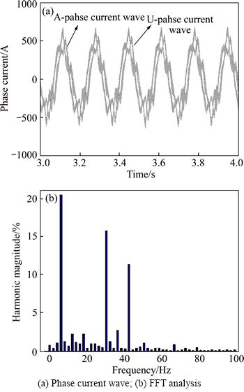
Fig. 9 Experiment curve obtained by adding PI controllers in x-y plane:
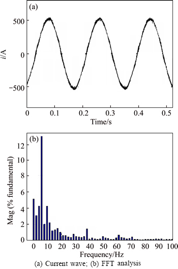
Fig. 10 Experiment curve obtained by adding PI controller with resonant controller in dx-dy plane:
7 Conclusions
A novel current vector decomposition controller is proposed for six-phase PMSM to obtain better control performance, and an improved synchronous rotating coordinate matrix is also presented. Compared with existing methods, only accounting for current unbalance in x-y plane, the proposed method has taken into account the current unbalances in both x-y plane and can eliminate them simultaneously at the steady state of operation. Consequently, the full compensation of current unbalance can be achieved, by which both the current unbalance between two sets and current unbalance between windings in each set are eliminated. Meanwhile, the 5th and 7th current harmonics caused by non-sinusoidal back EMF and inverter non-linearity can also be fully compensated. The effectiveness of proposed method is verified by a set of comparative simulation results.
References
[1] ZHAO Y, LIPO T. Space vector PWM control of dual three-phase induction machine using vector space decomposition [J]. IEEE Transactions on Industry Applications, 1995, 31(5): 1100-1109.
[2] LEVI E, BOJOI R, PROFUMO F, TOLIYAT H A, WILLIAMSON S. Multiphase induction motor drives��A technology statues review [J]. IET Electrical Power and Applications, 2007, 1(4): 489-516.
[3] LEVI E. Multiphase electric machines for variable-speed applications [J]. IEEE Transactions on Industrial Electronic, 2008, 55(5): 1893-1909.
[4] BOJOI R, LEVI E, FARINA F, TENCONI A, PROFUMO F. Dual three-phase induction motor drive with digital current control in the stationary reference frame [J]. IEE Proceeding of Electrical Power Applications, 2006, 153(1): 129-139.
[5] GOPAKUMAR K, RANGANATHAN V, BHAT S. Split-phase induction motor operation from PWM voltage source inverter [J]. IEEE Transactions on Industrial Applications, 1993, 29(5): 927-932.
[6] MOHAPATRA K, KANCHAN M, BAIJU P. Independent field- oriented control of two split-phase induction motors from a single six-phase inverter [J]. IEEE Transactions on Industrial Electronic, 2005, 52(5): 1372-1382.
[7] HADIOUCHE D, RAZIK H, REZZOUG A. On the modeling and design of dual-stator windings to minimize circulating harmonic currents for VSI fed AC machines [J]. IEEE Transactions on Industrial Applications, 2004, 40(2): 506-515.
[8] BOJOI R, FARINA F, LAZZARI M, PROFUMO F, TENCONI A. Analysis of the asymmetrical operation of dual three-phase induction machines [C]// IEEE International Electric Machines and Drives Conference. Madison: IEEE Conference Publications. 2003: 429- 435.
[9] HU Ya-shan, ZHU Zi-qiang, LIU Kan. Current control for dual three-phase permanent magnet synchronous motors accounting for current unbalance and harmonics [J]. IEEE Journal of Emerging and Selected Topics in Power Electronics, 2014, 2(2): 272-284.
[10] BOJOI R, LAZZARI M, FARINA F, TENCONI A. Digital field- oriented control for dual three-phase induction motor drives [J]. IEEE Transactions on Industry Applications, 2003, 39(3): 752-760.
[11] KARTTUNEN J, KALLIO S, PELTONIEMI P, ARTTUNEN J, KALLIO S, PELTONIEMI P, SIVENTOINEN P, PYRHONEN O. Decoupled vector control scheme for dual three- phase permanent magnet synchronous machines [J]. IEEE Transactions on Industrial Electronics, 2014, 61(5): 2185-2196.
[12] BOJOI R, LAZZARI M, FARINA F, BOJOI B, PROFUNMO F, TENCONI A. Digital synchronous frame current regulation for dual three-phase induction motor drives [C]// IEEE 34th Annual Power Electronics Specialist Conference. Mexico: IIEEE Conference Publications. 2003: 1475-1480.
[13] SINGH G, NAM K, LIM S. A simple indirect field-oriented control scheme for multiphase induction machine [J]. IEEE Transactions on Industrial Electronics, 2005, 52(4): 1177-1184.
[14] KARTTUNEN J, KALLIO S, PELTONIEMI, SIVENTOINEN P, PYRHONEN O. Dual three-phase permanent magnet synchronous machine supplied by two independent voltage source inverters [C]// International Symposium on Power Electronics, Electrical Drives, Automation and Motion. Sorrento, Italy: IEEE Conference Publications, 2012: 741-747.
[15] CHE H, LEVI E, JONES M, HEW W P, RAHIM N A. Current control methods for an asymmetrical six-phase induction motor drive [J]. IEEE Transactions on Power Electronics, 2014, 29(1): 407-417.
[16] CHE H, LEVI E, JONES M, DURAN J, HEW W P, RAHIM N A. Operation of a six-phase induction machine using series-connected machine-side converters [J]. IEEE Transactions on industrial Electronics, 2014, 61(1): 164-176.
[17] HARNEFORS L, NEE H. Model-based current control of AC machines using the internal model control method [J]. IEEE Transactions on Industry Applications, 1998, 34(1): 113-141.
[18] YEPES A, FREIJEDO F, O'SCAR L, DOVAL-GANDOY J. High- performance digital resonant controllers implemented with two integrators [J]. IEEE Transactions on Power Electronics, 2011, 26(2): 563-576.
[19] ZMOOD D, HOLMES D, BODE G. Frequency-domain analysis of three-phase linear current regulators [J]. IEEE Transactions on Industry Applications, 2001, 37(2): 601-610.
[20] LASCU C, ASIMINOAEI L, BOLDEA I, BLAABIERG F. High performance current controller for selective harmonic compensation in active power filters [J]. IEEE Transactions on Power Electronics, 2007, 22(5): 1826-1835.
[21] CHEN Ming-liang, WU Yu-han, YUAN Lei, XIAO F, XIE Z. Current control method of six-phase PMSM drive system with parallel back-to-back converters [C]// The 17th International Conference on Electrical Machines and Systems (ICEMS). Hangzhou, China: IEEE Conference Publications, 2014: 1612-1615.
(Edited by FANG Jing-hua)
Foundation item: Project(51507188) supported by the National Natural Science Foundation of China
Received date: 2015-02-09; Accepted date: 2015-05-06
Corresponding author: Yuan Lei, PhD; Tel: +86-25-80828466; E-mail: lei.yuan.v@qq.com
Abstract: The vector control algorithm based on vector space decomposition (VSD) transformation method has a more flexible control freedom, which can control the fundamental and harmonic subspace separately. To this end, a current vector decoupling control algorithm for six-phase permanent magnet synchronous motor (PMSM) is designed. Using the proposed synchronous rotating coordinate transformation matrix, the fundamental and harmonic components in d-q subspace are changed into direct current (DC) component, only using the traditional proportional integral (PI) controller can meet the non-static difference adjustment, and the controller parameter design method is given by employing internal model principle. In addition, in order to remove the 5th and 7th harmonic components of stator current, the current PI controller parallel with resonant controller is employed in x-y subspace to realize the specific harmonic component compensation. Simulation results verify the effectiveness of current decoupling vector controller.
