
��˨����������ѧģ�ͼ��������ʶ����
����ƽ1���Ծ���2����ΰ3�������2�����忭2
(1. �վ����մ�ѧ ��������ϵ������ ������130022��
2. ����������ѧ ��е����ѧԺ������ ������116024��
3. ������ѧ ��е�������Զ���ѧԺ������ ������110819)
ժ Ҫ��
����˨���������������������նȺ������նȵȲ�����������ϵͳ���Ӳ�λ�ķ��������ԣ���ϱ߽����������Ӳ�λ������������������������ɶȷ����Զ���ѧģ�͡����ö�߶ȷ��Ը�ϵͳ������⣬����������Ƶ����Ӧ�������ڷ����Խ�Ļ����ϣ��Ƶ���ϵͳ�����Ժͷ����Բ����ı���ʽ����ij������˨������Ϊ����ʵ�ⲻͬԤ�������µĹ������Ժ���Ӧ���ԣ�������ʶ����ͬԤ�������¸�ϵͳ�����Ժͷ����Բ�������������������������˨�����������ɶȷ�����ģ���Լ���Ӧ�IJ�����ʶ�������к����ԣ���˨���������е��͵���ʽ���������ԡ�
�ؼ��ʣ�
��˨�������������Զ���ѧģ����Ƶ����Ӧ��������߶ȷ���������ʶ��
��ͼ����ţ�V414 ���ױ�־�룺A ���±�ţ�1672-7207(2013)11-4483-09
Dynamic model and parameter identification method of bolted joint beam
WANG Boping1, ZHAI Jingyu2, SUN Wei3, CHEN Yugang2, HAN Qingkai2
(1. Department of Flight Theory, Aviation University of Air Force, Changchun 130022, China;
2. School of Mechanical Engineering, Dalian University of Technology, Dalian 116024, China;
2. School of Mechanical Engineering and Automation, Northeastern University, Shenyang 110819, China)
Abstract: For the cantilever bolted joint beam, parameters including linear bending stiffness and cubic stiffness were introduced to represent the nonlinear characteristics of the joint part. Combined with the boundary conditions and the continuity of joint part, a two degree of freedom (DOF) nonlinear dynamic model was constructed and the nonlinear frequency response function was obtained by means of multiple scales method. Based on the nonlinear solutions, expressions of linear and nonlinear parameters were deduced. A cantilever beam with bolted joint was taken as example to identify the linear and nonlinear parameters by measuring its natural characteristics and response characteristics at different preloads. The results show that the two DOF model and the identification method are reasonable. Typical ��softening�� nonlinearities can be also observed in the results.
Key words: bolted joint beam; nonlinear dynamic model; frequency response function; multiple scale method; parameter identification
��˨���ӷ�ʽ�ǻ�е�ṹ�г�����������ʽ���ڽ�ͨ�����ա����졢��Դ�������Լ�����ͨ�û�е�豸�й㷺Ӧ�á��ӻ�е����ѧ�ĽǶȣ��������ӽ���Ĵ��ڻ���ɽṹϵͳ�ֲ��նȺ�����ķ����ԣ���ijЩ������䶯�����ԱȽϸ��ӣ��������ַ�Ƶ���ֲ��ͻ��������[1]����˨��������������Ͻṹ�ĵ��ʹ�����ͬ�����и��ӵĶ���ѧ���ԣ������Ӳ�λ���з��������ԡ�
�ڹ���ʵ�ʷ����У��ܶ�����½���˨���������ж���ѧ������ͨ���ǻ������Ի�˼�룬��������Ϊ���Ե��ɺ������������ϣ�����ģ��������ʵ���ʶ�ķ���������Ӧ�ĵ�Ч���������ִ���������������˨���ӵķ����Ա��ʣ����������������ӽ�����ڶ����µĸ��ӷ������������⣬���ǻ�����������Ϸ��ͽӴ���Ԫ����������˨���ӽṹ�ķ���������Ԫģ��[2-3]����Щģ�ͱȽϸ����Ҳ�����ʹ�á���ˣ�����һ�������ġ����������Եġ�����˨����������ѧģ��ʮ����Ҫ[4]��
��˨���Ӳ�λ�ķ�����������ҪԴ��������Ħ�������ƺͲ�����϶ʱ���Ļ����йؽ����ĽӴ���Ħ�����������Ե��о��Ѿ��кܶ�ɹ�[5-7]��Iwanģ���ö������-�������Ԫ����������Ϻͽṹ�ij��ͣ�����ͨ����[8]�����øĽ���Iwan��ģ�Ϳ�������ģ��װ�����е���˨���ӽṹ�ķ���������[9]�����ҵõ���ʵ��֤��[10]�����Ӳ�λ�Ķ���ѧ��������������ʽ���������磬ʵ��۲쵽��Ͻṹ����Ƶ���½�[11]����ͬԤ�����غͼ��������µ��ͺ���ߵı仯[12]�ȡ���ˣ���˨�������Ķ���ѧģ���У����뿼�������Ӳ�λ�����еķ��������ԡ�
�����˨�����������Ķ���ѧģ�ͣ�ȷ����ģ�Ͳ����ر��Ƿ����Ի��ڵIJ���ʮ����Ҫ�����ڷ����Զ���ѧϵͳ��ģ�Ͳ�����ʶ���⣬��Ҫ��ʱ���Ƶ��2�����ģ�Ͳ�����ʱ���ʶ��������ʵʩ�������ܲ�������Ӱ��[13-14]��Ƶ���ʶ�������Ա������ݴ������㷨�������⣬���������鷽���������Ƶ���Ҫ��ϸߣ��Ҹ���������������ϵͳ[15-16]��
���ڷ�����ϵͳ�Ķ�߶ȷ������������Է������ⳣ������Զ���ѧ���̣�����������Ƶ����Ӧ����������ʵ��������Բ�����ʶ�����ֻ��ڶ�߶ȷ���Ƶ�����ʶ��������ֱ��ʶ��Ƶ�캯���ĹǸ����ߣ����ֱ�ۡ��������ַ��������ǻ���˺��м��κͲ��Ϸ����Ե��������ķ����Բ���[17]��Ҳʵ��������̬����˨�������ķ����Բ�����ʶ[18]��
��Դ�������״̬����˨���������������߽��������ɶȵġ�������������������Ե��������ζ���ѧ���̡�������۱߽������ͽ�ϲ����������������ö�߶ȷ�������⣬�ֱ������Գ߶��µ�Ƶ����Ӧ�����ͷ�����һ���Ƴ߶��µ�Ƶ����Ӧ���������ʵ����ԣ�������˨�����������Ժͷ����Բ�������ֵ�����Ƚ����ڲ�ͬ�������������µ���˨����������ʽ�����Եı仯��
1 ��˨�������Ķ���ѧģ�ͼ��������
1.1 ������ģ�ͼ�����˨���Ӳ�λ�����Ի���
ͼ1(a)��ʾΪ��˨�������ṹ������2����ͨ��������˨������ɣ���˨���������һ�˹̶�����һ�����ɡ�������ɶȷ�����ģ����ͼ1(b)��ʾ�����У�K1��K���ֱ��ʾ���Լ��иնȺ������նȣ�K3��ʾ������նȣ�C��ʾ��ϲ����������ϵ����
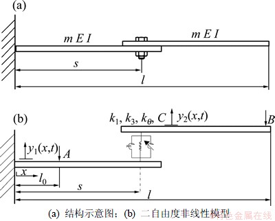
ͼ1 ��˨�������ṹ����ģ��
Fig.1 Bolted joint beam structure and simplified model
����Euler-Bernoulli�����ۣ���������˨�������Ķ����ɶ��������ε��˶��ַ���[19]��
 (1)
(1)
 (2)
(2)
ʽ�У�m��E��I�ֱ�Ϊ���ĵ�λ��������������ģ�����Ծأ� Ϊ���ĺ���λ�ơ�
 Ϊ�����ڵ�
A�������غɣ� ��
��
���DZ߽����������Ӵ���������������������״̬�ı߽�����Ϊ��
 (3)
(3)
 (4)
(4)
�����Ӳ�����ļ��������Ӧ����ȣ����� ���������ȿɵ�
 (5)
(5)
�ɼ�����ȿɵ�
 (6)
(6)
��K1Ϊ���Ӳ�λ���ļ��иնȣ��ɼ���ƽ��ɵ�
 (7)
(7)
��˨���Ӳ�λ���������������������ն� ��������ն�K3���������ϵ��C������������������������Ӳ�λ�����ƽ���ϵ�ɵ�

 (8)
(8)
1.2 ���ڶ�߶ȷ�����˨�������Ľ�����
������˨������������һ����Ƶ�ʸ�����������״̬�����Խ��⼤����ΪС��������ݶ�߶ȷ�[20]����

 ���˶��ַ���(1)��(2)����ת��Ϊ
 (9)
(9)
 (10)
(10)
�⼤����Ƶ�� �ӽ��ṹ��һ����Ƶ�ʣ���
 ��ʽ�У�
 Ϊ��г������
 ΪС������
����˨�������˶��ַ��̵Ľ��ò�ͬ��ʱ��߶�������� ��
�� ���������Բ�����
 (11)
(11)
 (12)
(12)
�����Խ�������ʽ(11)��(12)���뷽��(1)~(8)�������������������� ��
�� ��ϵ���ֱ���ȣ������һ����Ƶ�ʸ�����������״̬�µ��˶��ַ��̡��߽������������������ڲ�ͬʱ��߶��µķ��̡�
(1) ����
�˶��ַ���
 (13)
(13)
 (14)
(14)
�߽�����
 (15)
(15)
 (16)
(16)
����������
 (17)
(17)
 (18)
(18)
 (19)
(19)
 (20)
(20)
(2) ����
�˶��ַ���
 (21)
(21)
 (22)
(22)
�߽�����
 (23)
(23)
 (24)
(24)
����������
 (25)
(25)
 (26)
(26)
 (27)
(27)


 (28)
(28)
ʽ�У� ��
�� ��
�� ��
�� ��
�� ��
��
�ֱ�����ķ��̽�����⡣
(1) ������η��̵�һ������Ӧ��������ʽΪ
 (29)
(29)
 (30)
(30)
ʽ�У� Ϊ�ṹ��һ����Ƶ�ʣ�CcΪǰ��ĸ����
 Ϊһ������Ӧ�����ͺ�����
������Ľ�ʽ(29)��(30)��������ķ����У�ʽ(13)~(20)��ת��Ϊ
 (31)
(31)
 (32)
(32)
 (33)
(33)
 (34)
(34)
 (35)
(35)
 (36)
(36)
 (37)
(37)
 (38)
(38)
ʽ�У� ��
��
��ʽ(31)��(32)���ɽ���ʾΪ

 (39)
(39)

 (40)
(40)
�����ɸ���ʽ(33)��(34)�ı߽�������(35)~(38)������������ȷ����ϵ��Ai��Bi��Ci��Di��
(2) �������η��̵��㶯�⡣�跽����Ľ�Ϊ�ɳ����� �ͷdz�����Vi���
 (41)
(41)
 (42)
(42)
�����̵Ľ��������ķ����У��������ij�����ϵ����ͬ���Ӷ������������ʽ(21)~(28)��ת��Ϊ
 (43)
(43)
 (44)
(44)
 (45)
(45)
 (46)
(46)
 (47)
(47)
 (48)
(48)
 (49)
(49)

 (50)
(50)
���ǵ� ��YiΪ����⣬���Խ�ʽ(43)��(44)�ֱ����Y1��Y2������x������л��֣���ӿɵ�


 (51)
(51)
���ֲ����֣����������������ı߽�������������������ʽ(51)����ת��Ϊ

 (52)
(52)
����ʽ(52)�����˨�������ķ�����Ƶ����Ӧ�������� ��
�� ����ʽ(52)����ת��Ϊ
 (53)
(53)
��ʽ�ǹ������A��һ���ַ���ʽ����������ʽΪ
 (54)
(54)
��ʽ(54)����ʽ(53)���ֳ�ʵ�����鲿��������̬�˶���������� ��
�� ʱ�����Ƶ����·�����Ƶ����Ӧ��������
 (55)
(55)
 (56)
(56)
��Ӧ�أ���˨��������һ��Ƶ�������߷���Ϊ
 (57)
(57)
ʽ�У� ��
�� ��
��
 ��
��
2 ��˨������ģ�Ͳ����ı�ʶ����
2.1 ���Բ������ʶ��
��������̵Ľ�(ʽ(39)��(40))����������ı߽�����������������(ʽ(33)~(38))���ɵ�
 ��
�� (58)
(58)

 (59)
(59)

 (60)
(60)

 (61)
(61)


 (62)
(62)


 (63)
(63)
����8�������ǹ�������ķ��̽���Ai��Bi��Ci��Di�ķ����顣�ݿɽ�����������ϵ��������ʽ����Ϊ0�����ڸ�����ʽ�У�E��I��s��l�Ȳ������Ը���������β����Ͳ���ֱ��ȷ����
 Ҳ���Ը��ݽṹ���Ե����Թ���Ƶ�ʼ����á���ˣ���������ʽ���ȣ���Ӧ�ڲ�ͬ�����Թ���Ƶ�ʿɵõ�����k1��k���Ķ�Ԫ���η����飬���������Ӧ�����Թ���Ƶ�ʺ����ͺ�����
2.2 �����Բ������ʶ��
���ڻ�õķ����Է�Ƶ��Ӧ��������ʽ(57)����һ�������±任
 (64)
(64)
����Ƶ�캯��������[21]����Ƶ�캯���ķ�ֵ����ʽ(64)����
 (65)
(65)
 (66)
(66)
ʽ�У� ��
�� �ֱ�Ϊ�ڽṹ������Ƶ�캯����ֵ������Ӧ��ֵ�ͽ�г������
�ڷ��̵�����ͬʱ��������ת���������������õ�ԭ������ϵͳ�о�������ı���ʽΪ
 (67)
(67)
 (68)
(68)
ʽ�У�Ϊ�ṹ�����Թ���Ƶ�ʣ�Ϊ������Ƶ�캯���ķ�ֵƵ�ʡ�
3 ʵ��������
3.1 ʵ����̼������ݷ���
��ijһ��˨�������������ԣ�ʵ��װ����ͼ2��ʾ����ʵ��������ö����ذ��ֽ��Լ���װ�ڼо����ұ��ֲ��䡣
���Բ�ͬ��������ֵ����ͬ��˨Ԥ�������µ���������һ����Ƶ�ʸ������Ƶ�ʵ��µ�����Ӧ����һ����Ƶ�ʸ�����Ƶ����Ϊ26.9~28.4 Hz�����ö�Ƶ���������ķ�ʽ����������ֵ�ֱ�Ϊ2��4��6 N����˨Ԥ�����طֱ�Ϊ3��5��10��15 N��m��
ͼ3��ʾΪ��ͬ��˨Ԥ�����ء���ͬ��������ֵ�²�õ���˨�������������Ƶ�ʱ仯�����ߡ�
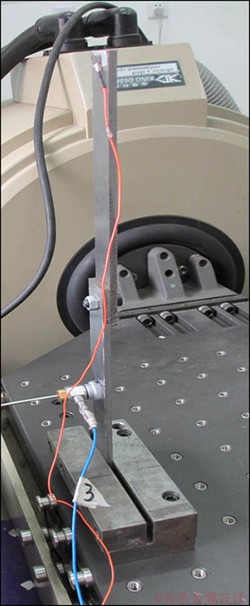
ͼ2 ��˨��������ʵ�����װ��
Fig.2 Experiment testing of bolted joint beam
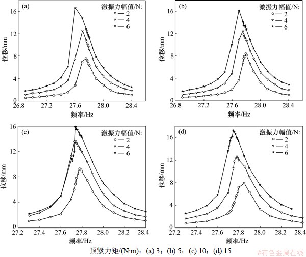
ͼ3 ��ͬԤ����������˨����������ķ�Ƶ��Ӧ
Fig.3 Frequency response of bolted joint beam under different levels of bolt preload
��ͼ3���Կ���������ͬ����˨Ԥ�������£����ż�������ֵ�����ӣ������ֵ������Ӧ��Ƶ�ʻ��С�����ֳ���ʽ�����ԡ�
3.2 ���Բ�����ʶ��
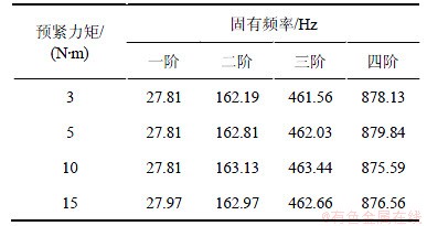
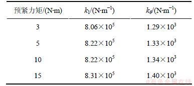
��1��ʾΪ��������ʵ����˨��������Ƶ��Ӧ���ߵĹ����ֵ������Ӧ�����Թ���Ƶ�ʡ��ӱ�1���Կ���������˨Ԥ�����ر仯������£���˨�����������Թ���Ƶ�ʻ���һ���仯��
���ݻ�õ���˨���������Թ���Ƶ�ʣ����ñ��ķ���ʶ����Ӧ�����Բ�����
��֪��˨�������IJ��ϲ���Ϊ����ģ��E=2.0��1011 Pa�����Ծ�I=5.4��10-10 m4���ṹ�ܳ�l=0.405 m����˨λ��s=0.185 m����λ��������m=1.413 kg/m��
����ʽ(58)~(63)��������ͺ���ϵ��Ai��Bi��Ci��Di (i=1, 2)�ķ����飬������������ʽ����Ϊ0�õ����ڼ��иն�k1�������ն�k����һ����Ԫ���η��̡���Ӧ��ʵ��õ���4�����Թ���Ƶ�ʣ��ɵõ�����k1��k����4�����̣�����Ϊ


 (69)
(69)
��ʽ(69)����ͼ�ⷨ[23]��⣬���Ի������˨Ԥ�����طֱ�Ϊ3��5��10��15 N��mʱ����˨��������ϲ�λ�ļ��иն�k1�������ն�k�����2��ʾ�����ڽṹ�Ĺ���Ƶ�ʱ仯�dz�С�������ļ��иն�k1�������ն�k�����Ҳ�dz�С��
��1 ��ͬԤ����������˨�����������Թ���Ƶ��
Table 1 Linear natural frequencies of bolted joint beam under different levels of bolt preload
��2 ��ͬԤ����������˨�������ļ��иնȺ������ն�
Table 2 Shear stiffness and bending stiffness of bolted joint beam under different levels of bolt preload
3.3 �����Բ�����ʶ��
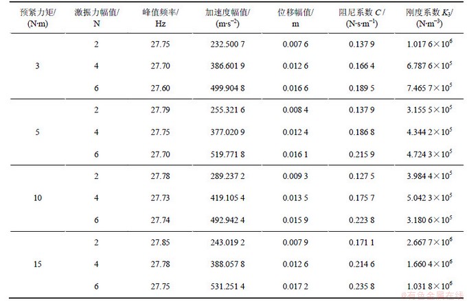
��ʵ��������õ��Ľṹ��Ӧ��ֵƵ�ʺͷ�ֵ����ʽ(67)��(68)������ʶ����һ������˨Ԥ�����غͼ�������ʱ����˨������������C�ͷ����Բ���K3��
��3��ʾΪ��˨�������ϵ���˨Ԥ�����طֱ�Ϊ3��5��10��15 N��mʱ����������Ӧ�ķ�ֵƵ�ʺͷ�ֵ���Լ�ʶ��õ�������ϵ���������ն���ϵ����
3.4 ʶ�����Ա�
����ʶ��������Ժͷ�����ģ�Ͳ��������Ի�ù�����˨����������������ѧģ�͡�����ʽ(64)��Ԥ��ṹ��һ����Ƶ�ʴ��ķ�����Ƶ����Ӧ���ߡ���ͼ4��ʾΪ��˨Ԥ������Ϊ15 N��mʱʵ����Ժͽ���Ԥ�����õ���һ�������߶Աȡ�
��ͼ4���Կ������ڹ����ֵ��������Ԥ��Ľ����ʵ����Խ�����Ǻϡ��ڷǹ����ֵ����ʵ����Եķ�ֵҪ��Щ����ˣ����������������ߵķ��������������Ϊ�����������˨����������ʽ���������Ըն�ģ�ͼ�����Ӧ�IJ���ʶ�������к����ԡ�
��3 ��ͬԤ����������˨�������ķ����Բ���
Table 3 Nonlinear parameters of bolted joint beam under different levels of bolt preload
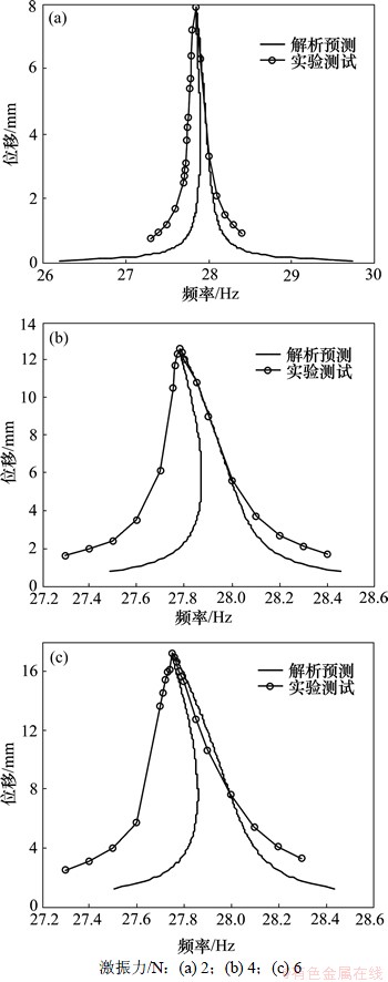
ͼ4 ��ͬ����������˨�������ķ�Ƶ��Ӧ����
Fig.4 Frequency responses of bolted joint beam under different levels of excitations
4 ����
(1) ��������˨�������Ķ����ɶȷ����Զ���ѧģ�ͣ������˱�����˨���Ӳ�λ�����������Ըն��������������ģ�;��к����ԣ��ܹ���ӳ��˨�������Ķ���ѧ���ԡ�
(2) ���ö�߶ȷ�������������˨�������ķ�����Ƶ����Ӧ�����⣬�ڴ˻����Ͽ�ʵ������ģ�Ͳ����ͷ����Բ���ģ�Ͳ����ĺ�����ʶ������ͨ��ʵ����Ի����˨�����������Թ���Ƶ�ʣ�Ȼ�����ϵͳ��Ƶ��������ʶ��˨���Ӳ�λ�����Լ��иնȺ������նȡ������ϵͳ����Ƶ�������벻ͬ�����µ�Ƶ����Ӧ�������жԱȣ���ʶ�õ������Ըն�ϵ����
(3) ������˨Ԥ�����ص�������˨���Ӳ�λ�����ԸնȲ������������Ըն��ȼ�С������ģ�Ϳ��ԽϺõر�������ʽ���������ԣ����ڹ��������ڵ�Ԥ����Ҫ�ȷǹ������ڵĸ�ȷ��
�ο����ף�
[1] Hartwigsen C J. Dynamics of jointed beam structures: Computational and experimental studies[D]. Urbana: University of Illinois at Urbana-Champaign. Aeronautical and Astronautical Engineering Department, 2002: 1-4.
[2] Abad J, Franco J, Celorrio R, et al. Design of experiments and energy dissipation analysis for a contact mechanics 3d model of frictional bolted lap joints[J]. Advances in Engineering Software, 2011, 45(1): 42-53.
[3] Kim J, Yoon J C, Kang B S. Finite element analysis and modeling of structure with bolted joints[J]. Applied Mathematical Modelling, 2007, 31(5): 895-911.
[4] Segalman D J, Gregory D L, Starr M J, et al. Handbook on dynamics of jointed structures[R]. Alberquerque: Sandia National Laboratories, 2009: 10-20.
[5] Ferri A. Friction damping and isolation systems[J]. Journal of Vibration and Acoustics, 1995, 117(B):196-206.
[6] Gaul L, Nitsche R. The role of friction in mechanical joints[J]. Applied Mechanics Reviews, 2001, 54(2): 93-106.
[7] Berger E. Friction modeling for dynamic system simulation[J]. Applied Mechanics Reviews, 2002, 55(6): 535-577.
[8] Iwan W D. A distributed-element model for hysteresis and its steady-state dynamic response[J]. Journal of Applied Mechanics, 1966, 4(33): 893-900.
[9] Song Y, Hartwigsen C, Mcfarland D, et al. Simulation of dynamics of beam structures with bolted joints using adjusted iwan beam elements[J]. Journal of Sound and Vibration, 2004, 273(1): 249-276.
[10] Gaul L, Lenz J. Nonlinear dynamics of structures assembled by bolted joints[J]. Acta Mechanica, 1997, 125(1): 169-181.
[11] Hartwigsen C J, Song Y, Mcfarland D M, et al. Experimental study of non-linear effects in a typical shear lap joint configuration[J]. Journal of Sound and Vibration, 2004, 277(1): 327-351.
[12] Ouyang H, Oldfield M, Mottershead J. Experimental and theoretical studies of a bolted joint excited by a torsional dynamic load[J]. International Journal of Mechanical Sciences, 2006, 48(12): 1447-1455.
[13] Mohammad K, Worden K, Tomlinson G. Direct parameter estimation for linear and non-linear structures[J]. Journal of Sound and Vibration, 1992, 152(3): 471-499.
[14] Yasuda K, Kamiya K. Experimental identification technique of nonlinear beams in time domain[J], Nonlinear Dynamics, 1999, 18(2): 185-202.
[15] Krauss R W, Nayfeh A H. Experimental nonlinear identification of a single mode of a transversely excited beam[J]. Nonlinear Dynamics, 1999, 18(1): 69-87.
[16] Yasuda K, Kamiya K, Komakine M. Experimental identification technique of vibrating structures with geometrical nonlinearity[J]. Journal of Applied Mechanics, 1997, 64(2): 275-290.
[17] Malatkar P. Nonlinear vibrations of cantilever beams and plates[D]. Blacksburg: Virginia Polytechnic Institute and State University. Department of Engineering Science and Mechanics, 2003: 1-115.
[18] Ahmadian H, Jalali H. Identification of bolted lap joints parameters in assembled structures[J]. Mechanical Systems and Signal Processing, 2007, 21(2): 1041-1050.
[19] Rao S S. Mechanical vibrations[M]. 5th ed. Englewood Cliffs: Prentice Hall, 2010: 1-94.
[20] Nayfeh A H, Mook D T. Nonlinear oscillations[M]. Weinheim: Wiley-VCH, 1995: 394-408.
[21] Ahmadian H, Mottershead J, Friswell M. Boundary condition identification by solving characteristic equations[J]. Journal of Sound and Vibration, 2001, 247(5): 755-763.
(�༭ �Կ�)
�ո����ڣ�2012-09-10�������ڣ�2013-01-12
������Ŀ�������ص��о���չ�ƻ���Ŀ(2012CB026000)��������Ȼ��ѧ����������Ŀ(51175070)
ͨ�����ߣ����忭(1969-)���У�ɽ�������ˣ����ڣ���ʿ����ʦ�����»�е����ѧ�о����绰��0411-84706750��E-mail: hanqingkai@dlut.edu.cn
ժҪ����Դ�������̬����˨���������������������նȺ������նȵȲ�����������ϵͳ���Ӳ�λ�ķ��������ԣ���ϱ߽����������Ӳ�λ������������������������ɶȷ����Զ���ѧģ�͡����ö�߶ȷ��Ը�ϵͳ������⣬����������Ƶ����Ӧ�������ڷ����Խ�Ļ����ϣ��Ƶ���ϵͳ�����Ժͷ����Բ����ı���ʽ����ij������˨������Ϊ����ʵ�ⲻͬԤ�������µĹ������Ժ���Ӧ���ԣ�������ʶ����ͬԤ�������¸�ϵͳ�����Ժͷ����Բ�������������������������˨�����������ɶȷ�����ģ���Լ���Ӧ�IJ�����ʶ�������к����ԣ���˨���������е��͵���ʽ���������ԡ�
