
Trans. Nonferrous Met. Soc. China 24(2014) 3621-3631
Extrusion force analysis of aluminum pipe fabricated by CASTEX using expansion combination die
Fu-rong CAO1, Jing-lin WEN1, Hua DING1, Zhao-dong WANG2, Chuan-ping YU3, Fei XIA1
1. School of Materials and Metallurgy, Northeastern University, Shenyang 110819, China;
2. State Key Laboratory of Rolling and Automation, Northeastern University, Shenyang 110819, China;
3. Dandong Feituo Aluminum Products Co., Ltd., Dandong 118000, China
Received 24 November 2013; accepted 14 April 2014
Abstract:
To determine the extrusion force of pipe fabricated by continuous casting and extrusion (CASTEX) using an expansion combination die, the metallic expansion combination die was divided into diversion zone, expansion zone, flow dividing zone, welding chamber, and sizing zone, and the corresponding stress formulae in various zones were established using the slab method. The deformation zones of CASTEX groove were divided into liquid and semisolid zone, solid primary gripping zone, and solid gripping zone, and the formulae of pipe extrusion forces were established. Experiments were carried out on the self-designed CASTEX machine to obtain the aluminum pipe and measure its extrusion force using the expansion combination die. The experimental results of radial extrusion force for aluminum pipe are in good agreement with the calculated ones.
Key words:
continuous casting and extrusion; continuous extrusion; expansion combination die; aluminum pipe; stress analysis; extrusion force;
1 Introduction
Unlike conventional extrusion [1,2] and other types of extrusion [3-5], CONFORM, continuous extrusion forming, turns the friction resistance between the billet and the container into the driving force of billet deformation. As long as various billets or feedstock such as rod, particles, and powders of aluminum, copper, and polymeric material are fed continuously into the entrance of CONFORM machine, a wide range of products such as wire, rod, profile, and tube that meet the requirements can be produced continuously at the exit of extrusion die. Since the appearance of CONFORM, its application in major industrial and scientific fields has been increasing. MITCHELL [6] pointed out that CONFORM was a commercially viable method of producing hollow sections and tubing for air conditioning, refrigeration and cable television applications. CHURCH [7] introduced the application of CONFORM to the production of sheathe cable and to the manufacture of various solid and hollow sections in Europe and put forward the development of an expansion chamber, leading to the die through which profile whose cross section was larger than that of the feedstock could be made. HAWKES and MORGAN [8] reported the CONFORM extrusion of copper or aluminum solid sections and the sheathing or cladding operations. LANGERWEGER and MADDOCK [9] and MADDOCK [10] changed the solid feedstock of CONFORM into molten metal and presented an innovative continuous casting and extrusion (CASTEX) machine with the expansion chamber. Although the idea of the expansion chamber was put forward, no report was available to produce real pipes in practical CASTEX process using an expansion combination die except Northeastern University in China. In recent years, RAAB et al [11] and XU et al [12] have explored the application of ECAP (equal channel angular pressing)-CONFORM to the fabrication of ultrafine-grained (UFG) aluminum wire and Al-6061 rod. Recently, FENG et al [13], YUN et al [14], and HE et al [15] have reported the continuous extrusion of Cu-0.16Cr-0.12Zr alloy, have investigated the continuous extrusion and rolling forming of copper strip, and achieved 200% elongation to failure at 473 K and 1��10-4s-1 in AZ31 magnesium alloy processed by ECAP-CONFORM, respectively.
The theoretical mechanics analysis and simulation on CONFORM or CASTEX process using finite element (FEM) simulation, upper bound method, slab method, and slip line method have been increasing. First, FEM simulation was carried out. PENG et al [16] predicted the processes of defect initiation and development during CONFORM process. KIM et al [17] investigated the effects of several process parameters, such as material flow, defect occurrence, temperature and effective strain distribution, on the process characteristics. CHO and JEONG [18] addressed a parametric investigation on the occurrence of the surface defect in CONFORM process using FEM simulation. YUN et al [19] and WEI et al [20] investigated the metallic flow, strain field and temperature field of UFG copper rod using continuous ECAP, simulated the deformation behavior of continuous ECAP and investigated the effect of die angle and contact friction on the strain and stress distribution, flow homogeneity, shear deformation and torque, respectively, by FEM method. ZHAO et al [21] investigated the process of aluminum sheath during continuous extrusion using FEM simulation. Second, upper bound analyses were conducted. CAO et al [22] and KIM et al [23] derived the upper bound driving power equation for the CASTEX and the CONFORM processes, respectively. Third, slab method was used to determine the extrusion force. TIROSH et al [24] established a unit pressure distribution equation of CONFORM extrusion for wire. SHI et al [25] got a formula of CASTEX force for aluminum-steel cladding wire. SONG et al [26] established a formula of CONFORM extrusion force for copper bar. CAO et al [27] derived a formula of CONFORM expanding extrusion force for Al-5Ti-1B alloy and pure aluminum solid sections. Fourth, SEGAL [28] utilized the slip line method to study the mechanics of continuous ECAP of rectangular billets.
In terms of aforementioned application and theoretical analysis, the authors developed a CASTEX process with the expansion combination die so that the pipe with cross section larger than that of the feedstock was produced, and the corresponding equipment and relevant tools were designed. According to literature survey, there was little information available reporting on the mechanics analysis of aluminum pipe processed by CASTEX extrusion using the slab method. In this work, by using the expansion combination die designed by ourselves, the CASTEX process was divided into several deformation zones and the extrusion stress formulae were derived zone by zone. On the basis of wheel groove force analysis, the tangential force and radial force of driving the wheel groove for the CASTEX process were determined. Experiments were carried out on the self-designed CASTEX machine to obtain aluminum pipes and to compare the experimental force with the calculated one.
2 Mechanics analysis of CASTEX process using expansion combination die
The schematic diagram of the CASTEX equipment using the expansion combination die is shown in Fig. 1. Molten metal flows from the entrance of extruding wheel into the extrusion cavity formed by the wheel groove and the grip segment. Under the action of friction forces imposed by the two sides of wheel groove and the bottom surface, the molten metal solidifies, is deformed in the extrusion cavity and extruded out of the extrusion die to obtain the pipe product in required shape and properties, as shown in Fig. 2.
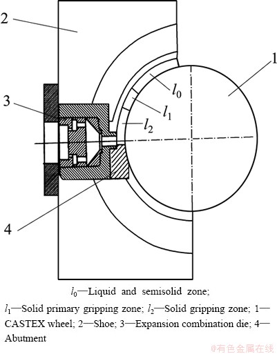
Fig. 1 Schematic diagram of CASTEX equipment using expansion combination die
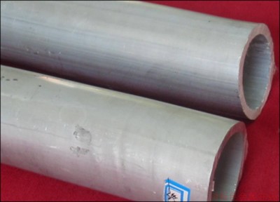
Fig. 2 Aluminum pipes produced by CASTEX using expansion combination die
According to the deformation characteristics of feedstock, the solidification and deformation processes in the wheel groove are divided into three deformation zones: liquid and semisolid zone l0, solid primary gripping zone l1 and solid gripping zone l2; the deformation process in the expansion combination die is divided into five deformation zones: 1) diversion zone, 2) expansion zone, 3) flow dividing zone, 4) welding chamber, and 5) sizing zone, as shown in Fig. 3. Mechanics analysis was carried out zone by zone from the beginning of the sizing zone of the die to the wheel entrance.
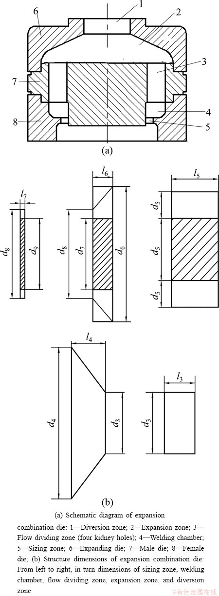
Fig. 3 Schematic diagrams of expansion combination die and its structure dimensions
2.1 Sizing zone
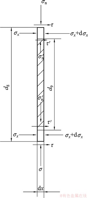
Fig. 4 Stress acting on infinitesimal element of sizing zone
The stress analysis in the sizing zone is shown in Fig. 4.  and
and  are normal pressures acting on the internal and external surfaces of the sizing zone of the die, respectively. is the normal pressure of the rigid die acting on the metal. ��n is the normal stress caused by the recovery of elastic deformation force. and are assumed to be approximately equal to ��s, the yield stress, i.e.,
  Because of relative movement between the billet and the sizing zone of the die, friction stress occurs. �ӡ� and �� are friction stresses acting on the internal and external surfaces of the sizing zone of the die, respectively, and abide by Coulomb��s law of friction. The coefficients of friction on the internal and external surfaces in the sizing zone of the die are assumed to be f7:
 (1)
(1)
The differential equation of static force equilibrium for the infinitesimal element along horizontal x axis direction is

 (2)
(2)
Equation (2) reduces to
 (3)
(3)
It is assumed that the stress acting on the boundary between the sizing zone and the welding chamber is ��7. Based on the boundary condition, when x=0, ��x=0; when x=l7, ��x=��7.
Definite integral of Eq. (3) becomes

Above equality reduces to
 (4)
(4)
where f7 is the coefficient of friction between the billet and the sizing zone of die, ��s is the flow stress of the material, l7 is the length of the sizing zone of the die, d8 is the diameter of the sizing zone of the die, and d9 is the diameter of mandril.
2.2 Welding chamber
The stresses acting on the infinitesimal element of the welding chamber are shown in Fig. 5. and are normal pressures acting on the internal and external surfaces of the welding chamber of the die, respectively.  and
and  where the semicone angle
 can be obtained according to the force equilibrium along vertical direction. For simplification, it is assumed that the normal pressures acting on the internal and external surfaces are approximately equal,
 , and their coefficients of friction are also the same. The shear stresses acting on the boundary between the movable metal and the ��dead�� metal (D.M.) zone attain the maximum values. The coefficients of friction obey
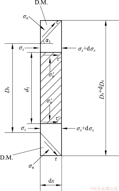
Fig. 5 Stresses acting on infinitesimal element of welding chamber
The differential equation of force equilibrium for the infinitesimal element along horizontal x axis direction is


 (5)
(5)
Neglecting differential quantities of the second order, in consideration of  , Eq. (5) reduces to

 (6)
(6)
Substituting Tresca��s yield criterion, ��n-��x=��s, into Eq. (6) leads to

 (7)
(7)
Let  , Eq. (7) becomes

 (8)
(8)
Rearranging Eq. (8) yields
 (9)
(9)
Let
 ,
,

Therefore,

 (10)
(10)
where C is a constant of integration.
Solving the above formula gives

 (11)
(11)
It is assumed that the stress acting on the boundary between the welding chamber and the flow dividing zone is ��6. Based on the boundary condition, when Dx=d8, ��x=��7; when Dx=d6, ��x=��6.
Equation (11) reduces to


 (12)
(12)
In Eq. (12), numerical integration for the second item shall be implemented to gain the calculated results.
2.3 Flow dividing zone
Flow dividing zone consists of four holes in kidney shape, as shown in Fig. 6. The flow dividing hole in kidney shape is assumed to be equivalent to a rectangle whose side lengths are h5 and b5. The depth of the hole is equal to l5. Friction stress is determined according to the maximum shear stress. The coefficient of friction is assumed to be  It is assumed that
  where and are the normal pressures.
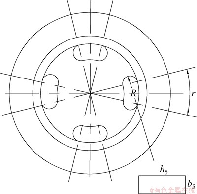
Fig. 6 Four flow dividing holes in male die of combination die
As shown in Fig. 7, the differential equation of force equilibrium for the infinitesimal element along horizontal x axis direction is
 (13)
(13)
 (14)
(14)
It is assumed that the stress acting on the boundary between the flow dividing zone and the expansion zone is ��5 and the length of flow dividing zone is l5. Based on the boundary condition, when x=0, ��x=��6; when x=l5, ��x=��5.
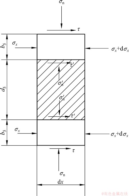
Fig. 7 Stress acting on infinitesimal element of flow dividing zone
Definite integral of Eq. (12) becomes
 (15)
(15)
Therefore,
 (16)
(16)
2.4 Expansion zone
The infinitesimal element to be chosen is shown in Fig. 8. The shear stress, ��, acting on the boundary between the metal and the die reaches the maximum value, and the coefficient of friction
  . The differential equation of force equilibrium for the infinitesimal element along horizontal x axis direction is

 (17)
(17)
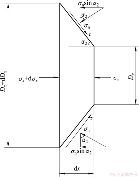
Fig. 8 Stress acting on infinitesimal element of expansion zone
Neglecting differential quantities of the second order, in consideration of  , Eq. (17) reduces to

 (18)
(18)
Hence,

Substituting Tresca��s yield criterion, ��n-��x=��s, into above formula leads to

Hence,
 (19)
(19)
It is assumed that the stress acting on the boundary between the expansion zone and the diversion zone is ��4. Based on the boundary condition, when Dx=d4, ��x=��5; when Dx=d3, ��x=��4.
Definite integral of Eq. (19) becomes
 (20)
(20)
Because
 ;
;


The limit of integration on the right of equality sign is reversed and becomes
 (21)
(21)
Therefore,
 (22)
(22)
where the semicone angle  .
.
2.5 Diversion zone
The infinitesimal element to be chosen is shown in Fig. 9. The shear stress, ��, acting on the boundary between the metal and the die reaches the maximum value,  . The differential equation of force equilibrium for the infinitesimal element along horizontal x axis direction is
 (23)
(23)
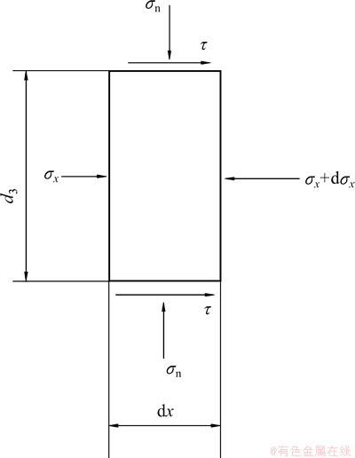
Fig. 9 Stress acting on infinitesimal element of diversion zone
Equation (23) reduces to
 (24)
(24)
Hence,
 (25)
(25)
It is assumed that the stress acting on the boundary between the diversion zone and the solid gripping zone is ��3 and the length of diversion zone is l3. Based on the boundary condition, when x=0, ��x=��4; when x=l3, ��x=��3.
Definite integral of Eq. (25) becomes
 (26)
(26)
Therefore,
 (27)
(27)
2.6 Liquid and semisolid zone, solid primary gripping zone and solid gripping zone
2.6.1 Lengths and stress distribution of liquid and semisolid zone, solid primary gripping zone and solid gripping zone
The deformation zones along the wheel groove are divided into liquid and semisolid zone l0, the solid primary gripping zone l1 and solid gripping zone l2, as shown in Fig. 10(a). The distribution of friction stress �� and tangential stress ��n in the wheel groove is shown in Fig. 10(b).
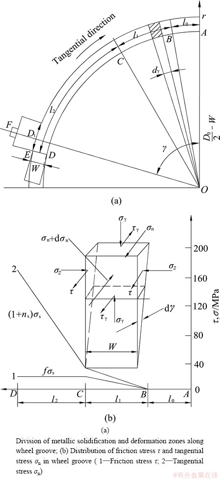
Fig. 10 Division of metallic solidification and deformation zones along wheel groove and stress distribution diagram
1) Length of zone l0
Liquid metal is poured into the groove and dynamic solidification occurs when friction stress ��=0 and tangential stress ��n=0. The length of l0 obeys
 (28)
(28)
where D0 is the wheel diameter, W is the groove height or width, l1 is the length of solid primary gripping zone, l2 is the length of solid gripping zone, Dt=d3, and �� is the wrapping angle in rad.
2) Length of l1 zone
Metal fills the groove gradually. �� starts from zero and increases till f��s; ��n, the tangential stress, starts from zero and increases till ��s, as shown in Fig. 10(b). The metal in section B-C is taken as the stress body. The metal in this section is subjected to the friction forces on both sides of the wheel groove and the tangential force is transferred from the front metal. The friction force of the groove bottom acting on the metal counteracts that of the grip segment acting on the metal in section B-C.
It is assumed that the friction stress in the section B-C is ��1, so  , which satisfies the boundary condition of l=0, ��1=0; l=l1, ��1=f��s. Due to the simultaneous action of friction forces on both sides of the wheel groove, the friction force of the wheel groove acting on the stress body becomes
 (29)
(29)
The tangential force is
 (30)
(30)
Static force equilibrium of section B-C gives
 (31)
(31)
Therefore,
 (32)
(32)
where f is the coefficient of friction and f=0.5.
3) Length of zone l2
�� is equal to f��s. Tangential stress ��n in front of the abutment increases, causing the metal to change the flow direction and the extrusion stress produced in the extrusion direction to reach ��3 which is required by extruding the metal in the expansion combination die out. Let ns=��3/��s, the metal in section C-D is taken as the stress body. The metal in this section is subjected to the friction forces on both sides of the wheel groove and the tangential force ��n is transferred from the abutment. The friction force of the groove bottom acting on the metal counteracts that of the grip segment acting on the metal in section C-D.
The tangential force equilibrium in section C-D gives
 (33)
(33)
According to Tresca��s yield criterion of maximum shear stress,
 (34)
(34)
Substituting  Eq. (34), and
  into Eq. (33) gives
 (35)
(35)
 (36)
(36)
2.6.2 Determination of CASTEX extrusion force
The CASTEX extrusion force means the tangential force, Pt, and the radial force, Pr, sustained by the wheel groove of CASTEX wheel. The wheel is taken as the force body. For the convenience of presentation, the force diagram of the wheel groove is shown in Fig. 11. The size of cross section of the groove is W��W.
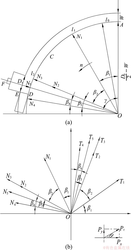
Fig. 11 Force diagrams of wheel groove for CASTEX extrusion
The forces acting on the side faces and the bottom surface of l1 zone (acting on the middle point of l1) are
 ,
,  (37)
(37)
The forces acting on the side faces and the bottom surface of l2 zone (acting on the middle point of l2) are
 ,
,  (38)
(38)
The flash forces caused by the clearance or gap (acting on the middle point of l2) are
 ,
,  (39)
(39)
The flash forces on the three sides of the abutment (acting on the middle point of Z) are
 ,
,  (40)
(40)
The forces of diversion zone acting on the wheel groove are
 ,
,  (41)
(41)
where b is the length of single side flash and Z is the length of flash caused by the leakage between the abutment and the wheel groove.
Thus, the tangential force of deformation material acting on the wheel groove is

 (42)
(42)
The radial force of deformation material acting on the wheel center, Pr, is determined by the following relation:
 (43)
(43)
 (44)
(44)
where Px is the horizontal component, Py is the vertical component, and �� is the direction angle.
Resolution of forces is carried out for Fig. 11(b) and leads to
 , i=1, 2, 3, 4, 5 (45)
Combining the above formulae for i, horizontal component, Px, and vertical component Py, of radial force, Pr, are obtained.


 (46)
(46)


 (47)
(47)
As actual directions of stress vectors are opposite to those shown in Fig. 11(b), it is necessary to add a minus sign before Px and Py and final Px and Py are obtained:


 (48)
(48)


 (49)
(49)
where
 ,
,
 ,
,  ,
,
 ,
,  .
.
These angles are determined according to the geometrical relation.
Equations (42), (43), (44), (48) and (49) are the derived formulae for radial CASTEX extrusion.
3 Experimental process and calculated results
3.1 Experimental process and results
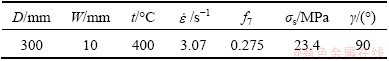
CASTEX tests of aluminum pipes were conducted on the self-designed CASTEX machine with the expansion combination die. The wheel diameter was 300 mm. Liquid metal at 710 ��C was poured into the rotary extrusion wheel groove and a pipe with a dimension of d50 mm��5 mm was obtained by extruding deformation. In the shoe, a sensor was mounted at the outlet side of the extrusion die to measure the radial force. Prior to the measurement of the radial force, the sensor was calibrated by a model DY-15 stabilized voltage power supply, a model YD-15 dynamic electrical resistance strain gauge and a model SC-16 light ray recording oscillograph on the universal tensile test machine. Thermocouples were inserted into the holes drilled on the grip segments and an X-Y four point temperature measuring device was used to measure the deformation temperature. The temperature that metal entered the die was measured to be 400 ��C. According to WEN [29], the flow stress, ��s, of aluminum at deformation temperature of 400 ��C and strain rate of 3.07 s-1 was 23.4 MPa and the coefficient of Coulomb��s friction, f7, was 0.275.
3.2 Calculated results
The technical parameters of CASTEX machine and extrusion process are shown in Table 1.
Table 1 Technical parameters of CASTEX machine and extrusion process
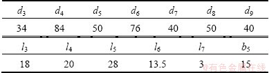
The structure dimensions of the expansion combination die corresponding to Fig. 3(b) are shown in Table 2.
Table 2 Structure dimensions of expansion combination die (mm)
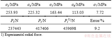
The calculated stresses in various deformation zones and the comparison of the calculated extrusion radial force with the experimental one are shown in Table 3. The experimental radial force is in good agreement with the calculated one with an error of less than 10% under the present experimental condition.
Table 3 Calculated stresses in various deformation zones and comparison of the calculated extrusion radial force with the experimental one
4 Conclusions
1) An expansion combination die for the CASTEX process is designed. The metallic expansion combination die is divided into diversion zone, expansion zone, flow dividing zone, welding chamber, and sizing zone. The corresponding stress formulae in various zones are established using the slab method.
2) The deformation zones of CASTEX groove are divided into liquid and semisolid zone, solid primary gripping zone, and solid gripping zone. The formulae of pipe extrusion forces are established.
3) Experiments were carried out on the self- designed CASTEX machine to obtain the aluminum pipe and measure its extrusion force using the expansion combination die. The experimental results of radial extrusion force for aluminum pipe are in good agreement with the calculated ones.
References
[1] LI Jing-yuan, XIE Jian-xin, JIN Jun-bing, WANG Zhi-xiang. Microstructural evolution of AZ91 magnesium alloy during extrusion and heat treatment [J]. Transactions of Nonferrous Metals Society of China, 2012, 22(5): 1028-1034.
[2] HAGHIGHAT H, MAHDAVI M M. Analysis and FEM simulation of extrusion process of bimetal tubes through rotating conical dies [J]. Transactions of Nonferrous Metals Society of China, 2013, 23(11): 3392-3399.
[3] YING Tao, HUANG Jian-ping, ZHENG Ming-yi, WU Kun. Influence of secondary extrusion on microstructures and mechanical properties of ZK60 Mg alloy processed by extrusion and ECAP [J]. Transactions of Nonferrous Metals Society of China, 2012, 22(8): 1896-1901.
[4] LIN Jin-bao, WANG Qu-dong, LIU Man-ping, CHEN Yong-jun, ROVEN H J. Finite element analysis of strain distribution in ZK60 Mg alloy during cyclic extrusion and compression [J]. Transactions of Nonferrous Metals Society of China, 2012, 22(8): 1902-1906.
[5] GUAN Ren-guo, ZHAO Zhan-yong, CHAO Run-ze, LIAN Chao, WEN Jing-lin. Simulation of temperature field and metal flow during continuous semisolid extending extrusion process of 6201 alloy tube [J]. Transactions of Nonferrous Metals Society of China, 2012, 22(5): 1182-1189.
[6] MITCHELL K J. Tube manufacture by the conform process [J]. Metallurgia, 1982, 8(9): 448-449.
[7] CHURCH F L. Extrusion goes continuous: Process promises economies [J]. Modern Metals, 1984, 40(11): 34-40.
[8] HAWKES D J, MORGAN R E. Conform extrusion [J]. Wire Industry, 1991, 58(6): 323-326.
[9] LANGERWEGER J, MADDOCK B. Production of aluminum wire directly from the molten metal [J]. Wire World International, 1986, 28(11-12): 179-181.
[10] MADDOCK B. Aluminum rod and other products by conform [J]. Wire Industry, 1987, 54(12): 728-731.
[11] RAAB G J, VALIEV R Z, LOWE T C, ZHU Y T. Continuous processing of ultrafine grained Al by ECAP-CONFORM [J]. Materials Science and Engineering A, 2004, 382(1-2): 30-34.
[12] XU C, SCHROENER S, BERBON P B, LANGDON T G. Principles of ECAP-CONFORM as a continuous process for achieving grain refinement: Application to an aluminum alloy [J]. Acta Materialia, 2010, 58(4): 1379-1386.
[13] FENG Hui, JIANG Hai-chang, YAN De-sheng, RONG Li-jian. Effect of continuous extrusion on the microstructure and mechanical properties of a CuCrZr alloy [J]. Materials Science and Engineering A, 2013, 582: 219-224.
[14] YUN Xin-bing, YOU Wei, ZHAO Ying, LI Bing, FAN Zhi-xin. Continuous extrusion and rolling forming velocity of copper strip [J]. Transactions of Nonferrous Metals Society of China, 2013, 23(4): 1108-1113.
[15] HE You-liang, GAO Fei, SONG Bao-yun, FU Rong, WU Gui-ming, LI Jian, JIANG Lan. Grain refinement of magnesium alloys by CONFORM: A continuous severe plastic deformation route? [J]. Materials Science Forum, 2012, 706-709: 1781-1786.
[16] PENG Ying-hong, RUAN Xue-yu, ZUO Tie-yong. Defect prediction during CONFORM process by FEM [J]. Journal of Materials Processing Technology, 1994, 45: 539-543.
[17] KIM Y H, CHO J R, JEONG H S, KIM K S, YOON S S. A study on optimal design for CONFORM process [J]. Journal of Materials Processing Technology, 1998, 80-81: 671-675.
[18] CHO J R, JEONG H S. Parametric investigation on the surface defect occurrence in CONFORM process by the finite element method [J]. Journal of Materials Processing Technology, 2000, 104(3): 236-243.
[19] YUN Xin-bing, SONG Bao-yun, CHEN Li. Ultra-fine grain copper prepared by continuous equal channel angular press [J]. The Chinese Journal of Nonferrous Metals, 2006, 16(9): 1563-1569. (in Chinese)
[20] WEI Wei, ZHANG Wei, WEI Kun-xia, ZHONG Yi, CHENG Gang, HU Jing. Finite element analysis of deformation behavior in continuous ECAP process [J]. Materials Science and Engineering A, 2009, 516: 111-118.
[21] ZHAO Ying, SONG Bao-yun, YUN Xin-bing, PEI Jiu-yang, JIA Chun-bo, YAN Zhi-yong. Effect of process parameters on sheath forming of continuous extrusion sheathing of aluminum [J]. Transactions of Nonferrous Metals Society of China, 2012, 22(2): 3073-3080.
[22] CAO Fu-rong, SHI Zhi-yuan, WEN Jing-lin. Upper-bound approach analysis of driving power of wheel for CASTEX [J]. Transactions of Nonferrous Metals Society of China, 1999, 9(1): 99-104.
[23] KIM Y H, CHO J R, KIM K S, JEONG H S, YOON S S. A study of the application of upper bound method to the CONFORM process [J]. Journal of Materials Processing Technology, 2000, 97(3): 153-157.
[24] TIROSH J, GROSSMAN G, GORDAN G. Theoretical and experimental study of the CONFORM metal forming process [J]. Journal of Engineering for Industry: Trans ASME, 1979, 101(2): 116-120.
[25] SHI Zhi-yuan, CAO Fu-rong, CHEN Yan-bo, WEN Jing-lin. The analysis and study of the CASTEX force of AS wire [J]. Journal of Materials Processing Technology, 1999, 86(1-3): 115-118.
[26] SONG Bao-yun, SONG Na-na, CHEN Li. Analysis of continuous extrusion extending forming force for wide copper bus-bar [J]. Journal of Plasticity Engineering, 2011, 18(4): 6-10. (in Chinese)
[27] CAO Fu-rong, WEN Jing-lin, DING Hua, WANG Zhao-dong, LI Ying-long, GUAN Ren-guo, HOU Hui. Force analysis and experimental study of pure aluminum and Al-5%Ti-1%B alloy continuous expansion extrusion forming process [J]. Transactions of Nonferrous Metals Society of China, 2013, 23(1): 201-207.
[28] SEGAL V M. Mechanics of continuous equal-channel angular extrusion [J]. Journal of Materials Processing Technology, 2010, 210(3): 542-549.
[29] WEN Jing-lin. Metallic extrusion and drawing technology [M]. Shenyang: Northeastern University Press, 1996: 57-59. (in Chinese).
��չ���ģ�����������ܲĵļ�ѹ������
�ܸ���1���¾���1���� ��1�����Ѷ�2���ڴ�ƽ3, �� ��1
1. ������ѧ ������ұ��ѧԺ������110819��
2. ������ѧ ���Ƽ����������Զ��������ص�ʵ���ң�����110819��
3. ����������Ʒ����˾������ 118000
ժ Ҫ��Ϊ��ȷ���ܲ���չ���ģ�����������̵ı���������������չ���ģ��ģǻ����Ϊ����������չ�������������������Ͷ�������������������������״̬�����п鷨��������Ӧ�����㹫ʽ������������������ǻ����ΪҺ��������̬������̬��ʼ�н�����̬�н����������ܲ�����������ѹ�����㹫ʽ����������Ƶ������������Ͻ���������չ���ģ��������ʵ�鲢�����伷ѹ������õľ���ѹ��ʵ���������ۼ������Ǻϡ�
�ؼ��ʣ�����������������ѹ����չ���ģ�����ܣ�Ӧ����������ѹ��
(Edited by Wei-ping CHEN)
Foundation item: Projects (51334006, 50274020) supported by the National Natural Science Foundation of China
Corresponding author: Fu-rong CAO; Tel: +86-24-83670183; E-mail: cfr-lff@163.com
DOI: 10.1016/S1003-6326(14)63507-X
Abstract: To determine the extrusion force of pipe fabricated by continuous casting and extrusion (CASTEX) using an expansion combination die, the metallic expansion combination die was divided into diversion zone, expansion zone, flow dividing zone, welding chamber, and sizing zone, and the corresponding stress formulae in various zones were established using the slab method. The deformation zones of CASTEX groove were divided into liquid and semisolid zone, solid primary gripping zone, and solid gripping zone, and the formulae of pipe extrusion forces were established. Experiments were carried out on the self-designed CASTEX machine to obtain the aluminum pipe and measure its extrusion force using the expansion combination die. The experimental results of radial extrusion force for aluminum pipe are in good agreement with the calculated ones.
