
J. Cent. South Univ. Technol. (2007)06-0858-06
DOI: 10.1007/s11771-007-0163-4
![]()
Buckling analysis of super-long rock-socketed filling piles in soft soil area by element free Galerkin method
ZOU Xin-jun(���¾�), ZHAO Ming-hua(������), LIU Guang-dong(���ⶰ)
(Institute of Geotechnical Engineering, Hunan University, Changsha 410082, China)
Abstract:
In order to discuss the buckling stability of super-long rock-socketed filling piles widely used in bridge engineering in soft soil area such as Dongting Lake, the second stability type was adopted instead of traditional first type, and a newly invented numerical analysis method, i.e. the element-free Galerkin method (EFGM), was introduced to consider the non-concordant deformation and nonlinearity of the pile-soil interface. Then, based on the nonlinear elastic-ideal plastic pile-soil interface model, a nonlinear iterative algorithm was given to analyze the pile-soil interaction, and a program for buckling analysis of piles by the EFGM (PBAP-EFGM) and arc length method was worked out as well. The application results in an engineering example show that, the shape of pile top load��settlement curve obtained by the program agrees well with the measured one, of which the difference may be caused mainly by those uncertain factors such as possible initial defects of pile shaft and the eccentric loading during the test process. However, the calculated critical load is very close with the measured ultimate load of the test pile, and the corresponding relative error is only 5.6%, far better than the calculated values by linear and nonlinear incremental buckling analysis (with a greater relative error of 37.0% and 15.4% respectively), which also verifies the rationality and feasibility of the present method.
Key words:
1 Introduction
In soft soil area such as the area around Dongting Lake in Hunan Province, the covering soil layer is soft and deep, pile foundations (especially super-long rock-socketed filling piles) have to be used to meet the requirements of bearing capacity and settlement by the superstructures (especially those wide-span bridges). For this kind of piles, the vertical bearing capacity is often determined by the allowable pile top settlement or the buckling stability of the pile shaft[1-2]. Especially when the covering soil around the pile shaft is soft or easy to get liquefied after vibration, and the unsupported part of pile shaft above the ground is too long, buckling failure of the pile shaft tends to take place easily, which is often unpredictable with serious consequences. However, until 1920s, buckling failure of piles was regarded as an important problem. And from then on, researchers at home and abroad have made a great deal of effort to solve this problem[3-7]. The findings of these researchers all verified that, buckling failure of piles in soft soil layers is possible and must be paid great attention. However, the available researching methods are all based on the first type of stability problem to determine the buckling critical load by characteristic values[8], in which the pile shaft is seemed as an ideal Euler compression bar and influences by many complex factors, such as pile-soil interaction, material or geometrical nonlinearity, and possible initial defects of pile shaft, cannot be considered. Furthermore, the obtained critical load is the upper limit of real values and not safe to use in engineering. Therefore, buckling stability of piles shaft should be regarded as the second type of stability problem and analyzed by numerical methods[9].
In fact, buckling stability of piles under vertical loading is a problem of pile-soil interaction. As a strong numerical tool in engineering, the finite element method (FEM) has found its great success in solid mechanics and structural analysis. But the mesh needed by FEM just makes it difficult to deal with the discontinuity and large deformation inconsistent with the original mesh lines. And sometimes re-meshing should be done, resulting in a more complex calculation, time waste and a lower accuracy degree of the result, even a non-convergent process. Therefore, the FEM is unsuitable to solve those problems in pile-soil interaction, such as how to deal with the stiffness disparity between the pile shaft and surrounding soil, and sliding or cracking deformations along the pile-soil interface. So, new types of numerical methods independent of mesh should be pursued.
Mesh-free or meshless methods have been invented just for this reason since 1970s. And according to various means of constructing shape function, quite a few kinds of mesh-free methods may be defined. But a common ground for different mesh-free methods is that, the approximate function is constructed by discrete points but not the divided mesh, i.e. no mesh is needed as that in FEM. This new kind of numerical method has been used successfully in some fields such as machine and aviation. And among those various mesh-free methods, the element free Galerkin method (EFGM) has favorable advantages such as stable solving process, high accuracy degree of result, convenient post-processing, eliminating volume lockup and simpler forms[10]. Therefore, the EFGM was introduced in this study to carry out the buckling analysis of super-long rock-socketed filling piles in soft soil area.
2 Method of moving least square in EFGM
In EFGM, the moving least square (MLS) is used to construct the approximate field function by discrete points in a local area[11], i.e. only information about the filed nodes is needed, while it is unnecessary to link those nodes into elements or mesh like FEM.
The function u(x) is used to describe the displacement, while the approximate displacement uh(x) at a point x (for two-dimensional problem, x=(x, y)T��u=(u, v)T ) can be expressed by MLS as
![]() (1)
(1)
where a(x) is an arbitrary function vector of x, pT(x) is a basic function vector by m-order integrate polynomial, in 2D problem which may be denoted as
![]() (2)
(2)
And the coefficient vector a(x)=[a1(x), a2(x), ��, am(x)]T may be derived by the field values at n nodes (x1, x2, ��, xn) in the support domain of point x. As for the support domain of point, it is actually a local area including a number of nodes, which may be used to determine the approximate field displacement of point x. And the shape of support domain of a point can be defined by a circle, a rectangle or others, as shown in Fig.1.
If the displacements of n nodes in the support domain of x are denoted by u1, u2, ��, un, respectively, the local approximate value may be obtained by MLS as
![]() (3)
(3)
In order to solve the coefficient vector a(x), a weighted L2 norm J(x) is constructed as
![]()
![]() (4)
(4)
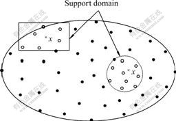
Fig. 1 Support domain of point in EFGM
where w(x��xI) is a chosen nonnegative, compact, continuous and derivable weight function, which is used to give the weight value at point x contributed by every node in the support domain. And the types of weight function often used mainly include exponential function and spline function[10].
Then, a(x) may be solved by minimizing the weighted residual in Eqn. (4), i.e. let ![]() , then
, then
![]() (5)
(5)
Substituting Eqn. (5) into Eqn. (1) leads to
![]()
![]() (6)
(6)
where ��I (x) and ��T(x) are the MLS shape function and the matrix of shape functions corresponding to n nodes in the support domain, respectively.
The moving weight function w(x) and coefficient vector a(x) that vary with dimensional coordinates are key points for MLS known from other least square methods. And if the weight value given by w(x) is constant, Eqn. (1) is just a standard approximation by non-moving least square methods, and a(x) also becomes a constant vector. However, as approximate function in MLS will not pass through every interpolated node, the constructed shape functions do not satisfy the property of Kronecker delta function, so additional means should be adopted to meet the essential boundary conditions, which is not as convenient as that in FEM.
3 Treatment of non�Cconcordant deformation at pile-soil interface
As shown in Fig.2, ��- and ��+ are used to denote the pile domain and surrounding soil domain, respectively. And outer boundaries of the two domains were expressed by �� + and �� -, with the corresponding outer normal line vector defined by n+ and n-.

Fig.2 Analytic model of pile-soil interaction by EFGM
3.1 Constitutive relation of pile-soil interface
The constitutive relation or model of pile-soil interface actually describes the relation between the tangential or normal stress and the corresponding strain. Since 1960s, a number of constitutive models about soil-structure interface, of which each has its own character and specific applicability, have been developed by researchers at home and abroad[12-14]. Among these models, most are used to describe the relation between the shear stress (��s) and relative displacement (s). After a synthetical comparison, nonlinear elastic-ideal plastic model was adopted in this paper to describe pile-soil interface[15], just as shown in Fig.3.
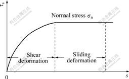
Fig.3 Nonlinear-perfect plastic interface model
3.2 Analysis of pile-soil contact
For general conditions, local coordinate system and its direction of pile-soil interface element is constructed in Fig.4.
In Fig.4, the inclination between local axis s and whole axis x is ��, and the node displacement under the local coordinate system and the whole coordinate system are denoted by u��, v�� and u, v, respectively. And the contacting normal stress ��n by tension is defined as positive, while anticlockwise tangential stress ��s is positive. If the coupling effect between the normal and tangential deformation is neglected, the magnitude of the corresponding stress can be determined as
![]() (7)
(7)
where ks and kn represent the tangential and normal stiffness coefficient, which may be valued approximately by elastic constant ��+2G and G, respectively, here �� and? G are known as Lame constant and shear modulus, and usually determined by the larger value on the two sides of the pile-soil interface.

Fig.4 Pile-soil interface element
And the displacement difference between pile nodes and soil nodes under the whole coordinate system may be used to determine the relative displacement on the pile-soil interface by coordinate transform as
 (8)
(8)
where T is the coordinate transform matrix, and
T =![]()
up and vp are displacements of node along directions x and y in pile domain under the whole coordinate system, us and vs are displacements of node along directions x and y in the surrounding soil domain under the whole coordinate system.
Using Eqn.(6), the displacement vector up and us of a node in the pile domain or surrounding soil domain may be expressed as
![]() ��
��![]() (9)
(9)
where ![]() and
and ![]() denote the node shape functions in pile and soil domain, respectively, u is a vector constructed by the displacements of n nodes in the support domain of point x.
denote the node shape functions in pile and soil domain, respectively, u is a vector constructed by the displacements of n nodes in the support domain of point x.
Based on Eqns.(7)-(9), the contribution by pile-soil interface element to the total equilibrium equation of the pile-soil system can be derived by variational principle as
 (10)
(10)
where
![]()
Then, Eqn. (10) may lead to
![]()
![]() (11)
(11)
From Eqn.(11), the contribution by interface elements to the total stiffness matrix is obtained as follows (the contribution to the load matrix equals zero):
![]()
![]() (12)
(12)
Spreading out Eqn.(12) and superposing the analytical result by using Gauss integral method to the total stiffness matrix of pile-soil system. Then, the non-concordant deformation in pile-soil interaction can be considered approximately in this way.
During the detailed analysis process, relevant failure criterions and needed parameters should first be given to judge the actual contacting conditions along the interface. And a nonlinear contacting iterative algorithm shown in Fig.5 is presented to do so in this study.
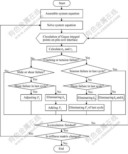
Fig.5 Nonlinear iterative algorithm for pile-soil interface
4 Nonlinear buckling analysis of piles by EFGM
Based on the above treatment method, a program for buckling analysis of piles by EFGM was worked out, which mainly included the following steps
Step 1 Use a number of uniformly or non-uniformly distributed nodes to disperse the pile domain, soil domain and boundary lines. Then, these dispersed node elements, together with the exerted load and displacement boundary conditions will constitute the analysis model by EFGM.
Step 2 Choose suitable basic functions, weight functions and sizes of support domain, and construct shape functions by MLS to obtain the approximate field function.
Step 3 Based on the control differential equation and the corresponding boundary conditions of pile-soil system, the disperse equation group under the whole coordinate system may be set up by shape functions obtained in Step 2 and the strong or weak integral form of the control differential equation of pile-soil system.
Step 4 Solve the buckling critical load of pile shaft by the disperse equation group set up in Step 3.
5 Applications
5.1 Survey of project and geology
Maocaojie Bridge is located in the area of Dongting Lake in north part of Hunan Province, China. Super-long rock-socketed filling pile foundation was designed to support the upper steel-tube concrete arch bridge. In order to investigate the bearing behavior of this type of piles and supply needed design parameters, a test pile with a diameter of 1.0 m and embedded length of 60.0 m was constructed around the site of main pier. Then a vertical loading test was carried out on the test pile.
Distributions of soil or rock layers in the field with the physico-mechanical parameters are listed in Table 1.
Table 1 Physical and mechanical properties of subsoil

5.2 Test result
During the loading process, when the pile top load is added up to 16.2 MN, the pile top settlement reaches 32.38 mm and can keep stable. After the exerted pile top load exceeds the predicted ultimate bearing capacity, the load step is halved. And when the load reaches 16.72 MN, it is hard to keep stable and the pile top settlement increases obviously. After being loaded up to 17.28 MN and kept stable for 5 min, the increasing rate of pile top settlement drops down obviously, and a sudden blare breaks out from underground. Then, an instant deviation of the pile top and cracks on the surround ground is observed. Furthermore, the pile top settlement cannot keep stable, and the oil pressure of the shunt-wound jacks drops down sharply to 11.88 MN. These loading phenomena and failure characters, as well as the data of strain gauges fixed to the down part of pile shaft turned from nonzero to zero, should all be caused by the buckling failure of pile shaft. And the ultimate load can be valued as 16.72 MN at the failure point of pile shaft 9-10 m deep underground.
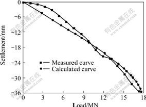
Fig.6 Calculated and measured pile top load-settlement curves
5.3 Result analysis
In order to simplify the problem reasonably, plane stress problem was assumed with a domain size of 10 times diameter in both radial direction and vertical direction under the pile tip. And 375 and 5740 node elements are used to disperse the pile domain and surrounding soil domain respectively, with 245 couples of contacting point-twin distributed along the pile-soil interface as well. As for needed calculation parameters, Table 1 lists the physico-mechanical properties of surrounding soil. And the elastic modulus and Poisson ratio of the concrete of pile shaft are 3.0��104 MPa and 0.167, respectively. In order to consider the contribution by steel bars in the concrete, the weighted average values for the elastic modulus, tensile strength and compressive strength of the reinforced concrete are 3.19��104 MPa, 5.27 and 15.86 MPa, respectively.
During calculation, a linear buckling analysis and nonlinear incremental buckling analysis were first performed with the calculated buckling load of pile shaft equal to 22.91 and 19.30 MN, respectively, which shows an obvious error compared with the measured ultimate pile top load of 16.72 MN.
Therefore, arc length method was introduced to calculate the buckling load of pile shaft more accurately. And the maximum total load to exert on the pile top was set as 19.00 MN, with the load at initial incremental step load and maximum incremental step set as 1% and 50% of the total load respectively after a previous testing calculation. And the analytical process shows that, when the exerted load on the pile top is added up to 17.65 MN, the calculated pile top settlement increases sharply, as shown in Fig.6, and cannot reach a point of convergence after a number of repeated iterative calculation process. Then, this point may be seemed as a minimum stable limit, and the corresponding load is just the buckling load of pile shaft, which shows a good agreement with the measured value.
However, some adjustments of the parameters are performed to obtain a result agreeable with those measured inner forces along the pile shaft and pile top settlement, that is, the inversed calculation parameters are used during the analysis. Although the relative error between the calculated and measured buckling loads is as small as 5.6%, an obvious difference between the calculated and measured pile top settlement still exists in Fig.6. This may be caused mainly by neglecting the eccentric load, possible initial defects of pile shaft and other complex factors. But compared with those traditional methods based on the first type of stability problem, the calculated buckling load by the present method is more reasonable and safer to evaluate the buckling stability of the test pile, which provides guidance for the design of pile foundation in the Maocaojie Bridge.
6 Conclusions
1) Buckling analysis of super-long rock-socketed filling piles should be seemed as the second type of stability problem instead of the first type, and numerical analysis by EFGM is more effective than FEM in considering influences by non-concordant deformation, nonlinear pile-soil contacting, geometrical nonlinearity by possible large flexure and other factors.
2) Based on the nonlinear elastic-ideal plastic contacting model, a nonlinear iterative algorithm is proposed to treat the non-concordant deformation along the pile-soil interface such as cracking and sliding.
3) A program for the buckling analysis of piles by EFGM is worked out and applied in an engineering example. The results show that the shape of pile top load-settlement curve obtained by the program agrees well with the measured one. Furthermore, the calculated critical load is very close to the measured ultimate load of the test pile, and the corresponding relative error is only 5.6%, far better than the calculated values by linear and nonlinear incremental buckling analysis (with a greater relative error of 37.0% and 15.4% respectively), which also verifies the rationality and feasibility of the present method in this study.
References
[1] ZHAO Ming-hua, YANG Ming-hui, ZOU Xin-jun. Vertical bearing capacity of pile based on load transfer model[J]. Journal of Central South University of Technology, 2005, 12(4): 488-493.
[2] ZOU Xin-jun, ZHAO Ming-hua, LIU Guang-dong. Nonlinear finite element analysis of pile group under inclined loads in stratified subgrade[J]. Journal of Central South University: Science and Technology, 2006, 37(4): 820-825. (in Chinese)
[3] LEE K L. Buckling of partially embedded piles in sand[J]. Journal of Soil Mechanics and Foundation Division, ASCE, 1968, 94(1): 255-270.
[4] REDDY A S, VALSANGKAR A J. Buckling of fully and partially embedded piles[J]. Journal of Soil Mechanics and Foundation Division, ASCE, 1970, 96(6): 1951-1965.
[5] ZHAO Ming-hua. Buckling equivalent length of piles[J]. Engineering Mechanics, 1984, 4(1): 94-105. (in Chinese)
[6] ZHAO Ming-hua. Buckling analysis and tests of bridge piles[J]. China Journal of Highway and Transport, 1990, 3(4): 47-57. (in Chinese)
[7] ZHAO Ming-hua, WANG Ji-bai. Buckling analysis of piles with side resistance considered[J]. Chinese Journal of Geotechnical Engineering, 1996, 18(3): 87-90. (in Chinese)
[8] YANG Wei-hao, REN Yan-long. Axial buckling analysis for bottom-fixed pile[J]. Chinese Journal of Rock Mechanics and Engineering, 2000, 19(3): 380-382. (in Chinese)
[9] LIU Guang-dong, LUO Han-quan. Stability of Framed Structure[M]. Beijing: The People��s Communications Press, 1998. (in Chinese)
[10] ZOU Xin-jun, ZHAO Ming-hua, LIU Guang-dong. Nonlinear buckling analysis of piles with high-rise pile cap[J]. Engineering Mechanics, 2003, 20(S): 342-345. (in Chinese)
[11] BELYTSCHKO T, LU Y Y, GU L. Element-free Galerkin methods[J]. International Journal for Numerical Methods in Engineering, 1994, 37(2): 229-256.
[12] LANCASTER P, SALKAUSKAS K. Surface generated by moving least squares methods[J]. Mathematics of Computation, 1981, 37(155): 141-158.
[13] GOODMAN R E, TAYLOR R L, BREKKE T L. A model for the mechanics of jointed rock[J]. Journal of the Soil Mechanics and Foundations Division, ASCE, 1968, 94(3): 637-660.
[14] DESAI C S, ZANMAN M M, LIGHTNER J G, et al. Thin layer element for interfaces and joints[J]. International Journal for Numerical and Analytical Methods in Geomechanics, 1984, 8(1): 19-43.
[15] YIN Zong-ze, ZHU Hong, XU Guo-hua. Numerical simulation of the deformation in the interface between soil and structural material[J]. Chinese Journal of Geotechnical Engineering, 1994, 16(3): 14-22. (in Chinese)
[16] LUAN Mao-tian, WU Ya-jun. A nonlinear elasto-perfectly plastic model of interface element for soil-structure interaction and its applications[J]. Rock and Soil Mechanics, 2004, 25(4): 507-513. (in Chinese)
Foundation item: Project(50378036) supported by the National Natural Science Foundation of ChinaReceived date: 2007-03-02; Accepted date: 2007-04-18
Corresponding author: ZOU Xin-jun, PhD��Tel: +86-731-8821659��E-mail: xjzouhd@yahoo.com
