
J. Cent. South Univ. Technol. (2008) 15(s1): 051-056
DOI: 10.1007/s11771-008-313-3
![]()
Comparison of rheological analytic model with numerical simulation in powder injection molding filling process
LIU Yue-jun(��Ծ��), LI Xiang-gang(�����), HUANG Yu-gang(�����),
WEI Shan-shan(κɺɺ), ZENG Guang-sheng(����ʤ)
(Key Laboratory of New Materials and Technology for Packaging, Hunan University of Technology,
Zhuzhou 412008, China)
Abstract:
Mathematical model of filling disk-shaped mold cavity in steady state was studied. And the mathematical model under vibration field was developed from the model in steady state. According to the model of filling disk-shaped mold cavity in steady state, the filling time, the distribution of velocity field and the pressure field were obtained. The analysis results from rheological analytic model were compared with the numerical simulation results using Moldflow software in the powder injection molding
Key words:
1 Introduction
Powder injection molding(PIM) is a derivative of polymer injection moulding and uses the same technology, along with batch sintering processes used in powder metallurgy and ceramic processing[1]. In recent years, this technology has moved from the laboratory to commercial production in the electronic, computer, medical and chemical industries. It is an important technique to introduce the vibration force field into the forming process of PIM. The injection molding stage, which is one of the most important procedures, can greatly influence the mechanical properties of the component. With the analysis technology, computer aided engineering (CAE) can help to simulate the widest application range of injection molding processes to optimize design and manufacturability of mould and product, and shorten time-to-market[2-4]. The study on the computer simulation of PIM just starts, and the study on the computer simulation is few. Mathematical model of filling disk-shaped mold cavity in steady state and under vibration field was studied in this work. And the analysis results from rheological analytic model were compared with the numerical simulation results using Moldflow software in the powder injection molding filling process. Through the comparison, the drawbacks of these models were pointed out, which would provide a theoretical reference for the establishment of correct model in the future.
2.1 Rheological analytic model in steady state
2.1.1 Establishment of physical model
PIM is capable of transforming complex designs into high precision, high final properties, and net-shaped products, so the filling process is complex too. If the filling process is seen as a nonisothermal and unsteady flow, it is difficult to analyze. In many cases, the mould cavity can be divided into some individual parts and accordingly the complex flow can be seen as the combination of several simple flows[5]. Therefore, it is useful to study the one-dimensional flow model and two-dimensional flow model. The flow of PIM feed stock in the filling process can be seen as generalized Hele-Shaw flow[6-10]. In this work, the process of filling disk-shaped mold cavity was studied and the distribution of velocity field and pressure field was obtained.
The radial flow is one of the basic flows in the disk-shaped mold cavity. The physical model is shown in Fig.1. Since the disk-shaped mould cavity is symmetrical, we can only study half of it for convenience of study. Supposing the height and the radius of mould are 2h and
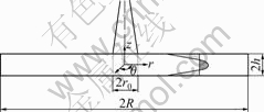
Fig.1 Physical model of center-gated disk
R, respectively, the radius of injection mold gate is r0, and time is denoted by t.
2.1.2 Establishment of mathematical model
Since the disk-shaped mould cavity is axial symmetrically, the selection of coordinate system is shown in Fig.1, the z axis coincided with central axis, and the r axis is on the middle plane between two surfaces. In order to discuss conveniently and simplify the problems, it was assumed as follows.
1) The feed stock melt is continuum melt, which means powder and adhesive are well-mixed and there is no air bubble in it.
2) The influence of elastic force, mass force and inertial force is neglected.
3) The feedstock is incompressible.
4) The flow of the feed stock is laminar flow, well-developed, and no wall slip; foundation effect, entrance effect and atmospheric pressure are neglected.
5) r0��2h���� R, the flow of feed stock melt is radial flow, and the axial direction flow and the circumferential flow are neglected. The filling process is isothermal process.
6) When t=0, the feed stock takes up some volume which takes z axis as center, radius is r0 and height is h in mould cavity.
According to the assumption above, the governing equations describing the filling process can be simplified as follows.
Continuity equation under cylindrical coordinate system is
![]() (1)
(1)
Motion equation in r direction is
![]() (2)
(2)
Motion equation in z direction is
![]() (3)
(3)
2.1.3 Boundary condition
1) Velocity boundary condition
When z=h, there is no wall slip,
vr(r, h)=0, vz(r, h)=0 (4)
When z=0,
![]() (5)
(5)
2) Flow rate boundary condition
The flow rate in the entrance is Q.
3) Pressure boundary condition
When t=0, the pressure in the entrance is zero, and the pressure of the flow front is zero.
2.1.4 Constitutive equation
Choose the power law as the constitutive equation:
According to the simplification and derivation of the mathematical model, the conclusions are obtained as follows.
2.1.5 Position of feed stock flow front
Under the premise of invariable flow rate, when time is t, the position of feed stock flow front r(t) is
![]() (7)
(7)
2.1.6 Velocity distribution
The velocity distribution can be expressed as
![]() (8)
(8)
By substituting Eqn.(7) into Eqn.(8), the following formula may be obtained:
 (9)
(9)
The filling time can be expressed as
![]() (10)
(10)
2.1.8 Distribution of pressure
The entrance pressure can be expressed as
![]() (11)
(11)
The moment when the mould cavity is full of the feed stock, the pressure in the place where the radius is r is as follows:
![]() (12)
(12)
2.2 Flow under vibration force field
2.2.1 Change of mathematical model
The flow rate boundary changes into the following forms:
![]() (13)
(13)
where Q is the average flow rate, A is the amplitude, �� is the circular frequency of vibration.
Similar to the simplification and derivation of the mathematical model in steady state, the conclusions are obtained as follows.
2.2.2 Position of feed stock flow front
Under the premise of invariable flow rate, when time is t, the position of feed stock flow front r(t) is
![]() (14)
(14)
2.2.3 Velocity distribution
The velocity distribution can be expressed as
![]() (15)
(15)
By substituting Eqn.(14) into Eqn.(15), the following Eqn. may be obtained:

[h1+1/n-z1+1/n] (16)
2.2.4 Filling time
The filling time can be expressed as
![]() (17)
(17)
2.2.5 Distribution of pressure
The entrance pressure can be expressed as

 (18)
(18)
The entrance pressure above in a vibration cycle T0 is averaged as

 (19)
(19)
At the moment when the mould cavity is full of the feed stock, the pressure in the place where the radius is r is as follows:
 (20)
(20)
3 Comparison of rheological analytic model with numerical simulation using Moldflow software
Moldflow is an engineering simulation software used to optimize part and mold designs for the plastics injection molding industry. Since Moldflow is relatively mature, through the comparison of rheological analytic model with numerical simulation using Moldflow software in the powder injection molding filling process, we can point out the drawbacks of these models that will provide a theoretical reference for the establishment of correct model both in steady state and under vibration force field in the future.
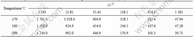
The following parameters are obtained according actual production. W-Ni-Fe feed stock is a kind of industrialized feed stock whose viscosity properties are listed as Table 1.
Fit the viscosity of W-Ni-Fe feed stock under different shear rates at 180 �� according to the power law:
![]()
that is
![]() (21)
(21)
The constitutive equation used in Moldflow soft-
Table 1 Viscosity of W-Ni-Fe feedstock at different temperatures and shear rates (Pa?s)
ware is cross-WLF equation:
 (22)
(22)
The viscosity of W-Ni-Fe feed stock under different shear rates according to the cross-WLF equation were fitted, and the constants in above equations are as follows: n=0.222 29, Tau*=16 518.99, D1= 4.85��1014 Pa?s, D2=340.09 K, A1=28.82, A2=12.05 K.
Flow rate Q is 2.649 cm3/s; radius of mould cavity R is 40 mm; depth of mould cavity is 2 mm, namely h= 1 mm; the diameter of the gate is 3 mm, namely r0=1.5 mm; according to the power law ![]() , that is n=0.375, K=4 761.
, that is n=0.375, K=4 761.
According to the conclusion above, the filling time is
![]()
The flow rate was set as 2.649 cm3/s, and the temperature of mould was set as 180 and 40 ��, respectively. The fit result of cross-WLF equation in the Moldflow was imported, then simulation by Moldflow was done, and the results are shown in Fig.2.
We can see that, the filling time calculated by the mathematic model and the Moldflow software is basically identical, and influence of temperature is little.
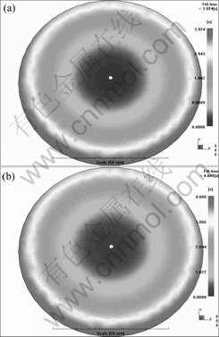
Fig.2 Simulation results of Moldflow software under different mold temperatures: (a) 180 ��; (b) 40 ��
According to the velocity distribution formula, we can obtain:
![]()
The change trend of vr with radius and height of mold is shown in Fig.3.
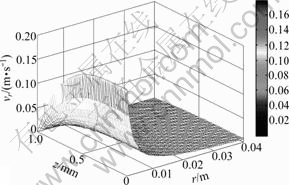
Fig.3 Change trend of vr with radius and height of mold
Compared with the flow process simulation using Moldflow (Fig.4), we can see that the velocity of the feed stock decreases when the radius and height increase, which is identical with the simulation results of
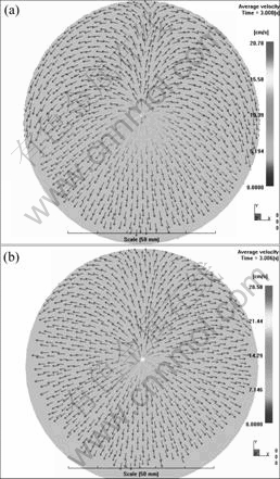
Fig.4 Flow process simulation using Moldflow software
Moldflow software. The influence of mould temperature is little.
According to the pressure distribution, the pressure change with the time at the cavity gate can be expressed as
p0(t)=7.570 9��106[(4.216��10-4t+2.25��10-6)0.312 5-0.017 2]
The change trend of theoretical results of the pressure at the cavity gate with the time is shown in Fig.5.
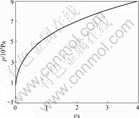
Fig.5 Theoretical results of pressure change with time at cavity gate
The flow rate was set as 2.649 cm3/s, and the temperature of mould was as 180 �� and the fit result of cross-WLF equation was imported in the Moldflow. Then simulation was done using Moldflow, and the Moldflow simulation result of the pressure at the cavity gate that changes with the time is shown in Fig.6.
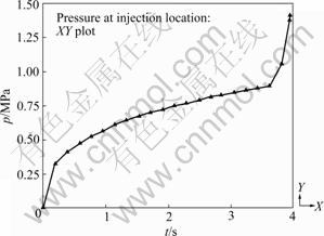
Fig.6 Moldflow simulation result of pressure change at cavity gate with time
We can see that, the calculated results by the mathematic model and the Moldflow software are basically identical based on the assumption proposed above.
However, the mould temperature is low in most of the actual productions. Whether the assumption that the mould temperature is 180 �� is reasonable or not should be discused. The temperature of the mould was changed to 40 �� in the Moldflow software, the simulation result is shown in Fig.7.
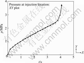
Fig.7 Moldflow simulation under mold temperature of 40 ��
We can see that, because of the lower mould temperature and the increase of viscosity, the pressure at the cavity gate increases more than one time. Therefore, the influence of temperature cannot be neglected, and the mathematical model should be developed using the heat transfer theory.
4 Conclusions
1) Mathematical model of filling disk-shaped mold cavity in steady state was studied. And the mathematical model under vibration field was developed from the model in steady state. According to the model of filling disk-shaped mold cavity in steady state, the filling time, the distribution of velocity field and the pressure field were obtained.
2) The analysis results from rheological analytic model were compared with the numerical simulation results using Moldflow software in the powder injection molding filling process. It is found that the calculated results by the mathematic model and the Moldflow soft ware are basically identical except the influence of temperature is distinct when calculated the pressure change at the cavity gate with the time, while it can be neglected in other situation.
3) Since the influence of temperature is obvious when calculated the pressure at the cavity gate, the mathematical model should be developed using the heat transfer theory.
References
[1] GERMAN R M, BOSE A. Injection molding of metals and ceramics [M]. Princeton: MPIF, 1997: 1-2.
[2] HIEBER C A, SHEN S F. A finite-element/finite-different simulation of the injection molding filing process [J]. Journal of Non-Newtonian Fluid Mechanics, 1980, 7: 1-32.
[3] HETUJ F, GAO D M, GARCIA-REJON A, SLLOUM G. First joint tropical conference on processing [C]// Structure and Properties of Polymeric Materials, Chicago, 1996.
[4] COUPEZ T, DABOUSSY D, BIGOT E, BATKAM S, A-GASSANT J F. 16th Annual Meeting of Polymer Processing Society. Shanghai, China, 2000.
[5] YUAN Zhong-shuang, LI De-qun, XIAO Jing-rong. A review of flow simulation in injection mold [J]. China Plastics, 1993, 7(1): 4-10. (in Chinese)
[6] NAJIMI L A, LEE D. Modelling of mold filling process for powder injection molding [J]. Polym Eng Sci, 1991, 31(5): 1137-1148.
[7] CHANG H H, HIEBER C A, WANG K K. A unified simulation of the filling and post filling stages in injection molding (part I): Formulation [J]. Folym Eng Sci, 1991, 31(2): 116-124.
[8] GUAN Qing, SHEN Kai-zhi. Numerical analysis of mold filling process in injection molding [J]. China Plastics, 1990, 4(20): 81-90. (in Chinese)
[9] WANG Li-xia, LIU Chun-tai. 3D flow analysis of plastic injection molding [J]. Journal of Zhengzhou Institute of Technology, 1995, 16(2): 101-108. (in Chinese)
[10] WU Ying-hui, WANG Peng-ju. Boundary element method for the flow simulation of injection mould filling [J]. China Plastics, 1996, 10(5): 78-80. (in Chinese)
(Edited by LI Xiang-qun)
Foundation item: Project(10672197) supported by the National Natural Science Foundation of China; Project(07JJ1001) supported by the Natural Science Foundation of Hunan Province for Distinguished Young Scholars, China
Received date: 2008-06-25; Accepted date: 2008-08-05
Corresponding author: LIU Yue-jun, Doctor, Professor; Tel: +86-733-2182103; E-mail: yjliu_2005@126.com
